Page is loading ...

Homeowner’s
Installation and
Operating Manual
For use in Europe
30003841 10/10 Rev. 9
0968
Defiant cover
11/00

Defiant® Woodburning Stove
30003841
This manual describes the installation, operation, and maintenance of the Vermont Castings Defiant Model 1945CE
catalytic-equipped wood burning heater. This heater meets the U.S. Environmental Protection Agency’s emission lim-
its for wood heaters sold on or after July 1, 1990. Under specific test conditions this heater has been shown to deliver
heat up to 1.6 kW (43,000 BTU/hr).
The Defiant Model #1945CE has been tested to current standards. The test standards are UL-148 and UL-737 for
the United States, and EN1340:001 + A:004 for Europe. The Defiant is listed for burning wood only. Do not burn
other fuels. The Defiant is approved for use in manufactured (mobile) homes only in the United States, and only when
installed with Vermont Castings Mobile Home Kit No. 1900.
We recommend that you hire a professional installer to install your stove, or to advise you on the installation should
you attempt to install it yourself.
Please read this entire manual before you install and use your new stove. Failure to follow instructions may result in
property damage, bodily injury, or even death.
Congratulations on your choice of a Vermont Castings Defiant stove. With this purchase you have made a commit-
ment to make the hearth a place of warmth, beauty and comfort in your home. At MHSC, we share that joy and appre-
ciation for the hearth. We assure you that your cast-iron Vermont Castings stove has been made with the utmost care
and will provide you with many years of service.
As you become acquainted with your new stove, you will find that its appearance is matched by its functionality, due to
cast iron’s unique ability to absorb and radiate heat.
Also, MHSC products are among the cleanest-burning wood stoves and fireplaces available today. As an owner of a
Vermont Castings stove, you make a strong statement for pollution-free energy. However, clean burning depends on
both the manufacturer and the operator. Please read this manual carefully to understand how to properly operate and
maintain your stove.
At MHSC, we are equally committed to your satisfaction as a customer. That is why we maintain an exclusive network
of the finest dealers in the industry. Our dealers are chosen for their expertise and dedication to customer service.
They are factory-trained and knowledgeable about every MHSC product. Feel free to contact your Authorized Vermont
Castings Dealer anytime you have a particular question about your stove or its performance.
This manual contains valuable instructions on the installation and operation of your Vermont Castings Defiant. It also
contains useful information on maintenance. Please read the manual thoroughly and keep it as a reference.
Sincerely,
All of Us at MHSC

3
Defiant® Woodburning Stove
30003841
Specifications ................................................. 4
Installation ...................................................... 5
Clearances ................................................... 10
Assembly ...................................................... 1
Operation ...................................................... 13
Draft Management ........................................ 0
Maintenance ................................................. 3
Appendix: Catalytic Combustor .................... 9
Appendix:
Chimney & Fireplace Hazards ............... 30
Parts Diagram............................................... 31
Warranty ....................................................... 35
No wood-burning appliance, save for Ben Franklin’s Pennsylvania Fireplace, has a stronger heritage than the Ver-
mont Castings Defiant. Named for a 19th-century steamship, the original Vermont Castings Defiant Wood Stove came
to epitomize America’s resolve and independence during the Energy Crisis of the 1970s.
The year was 1975. With energy prices going through the roof, and not an attractive or efficient wood stove to be
found anywhere, two entrepreneurs set out to create a stove that was a thing of beauty as well as utility. Finely crafted
from cast iron, the Defiant was the first wood stove to combine an artistically designed exterior with a methodically
engineered interior, using new technologies for efficient combustion.
Americans purchased over a quarter-million Defiants, as they rediscovered the common sense of heating with wood,
a home-grown fuel with none of the political and economic entanglements of foreign oil.
Thirteen years later, in 1988, Vermont Castings ‘retired’ the Defiant, replacing it with modern wood-burners such as
the Encore.
With its 1998 return, the new Defiant incorporates all the finest aesthetic, convenience, and performance features to
be found on any wood stove. In a sense, the new Defiant has been 3 years in the making.
Due to its significant role in American history, the original model Defiant is in the permanent collection of the Smithso-
nian Institution. Each new purchase of the Defiant stove continues that history.
Warming Shelf
#1560 Classic #156 Sand
#1553 Brown Majolica #1565 Bordeaux
#1555 Biscuit #1566 Forest Green
#1556 Chestnut Brown #1567 Midnight Blue
#1557 Ebony
#1558 Vt. Classic Green
#1900 Mobile Home Kit
#1904 Outside Air Adapter
#1905 Bottom Heat Shield Kit
#1901 Rear Heat Shield Kit
#1860 6” x 1” Oval Starter Pipe
A line of porcelain enamel stove pipe is also avail-
able.

4
Defiant® Woodburning Stove
30003841
Nominal heat output .............1.6 kW (43,000 BTU/hr)1
Minimum flue draught ......................1 Pa (0.048” WG)
Mean flue gas temp ..............................330° C (65° F)
Efficiency (space heating) ...................................76.7%
Area heated .................. Up to 3 sq. m (,400 sq. ft.)1
Fuel size/type ................ 559 - 610 mm ( - 4”) wood
Flue mass gas flow ............................................. 9.6 g/s
CO Emissions (@ 13%O).............................1800 ppm
Loading .....................................................Front and top
Chimney Connector:
for 03 mm (8”) flue collar .... 03 mm (8”) diameter
Chimney Flue Size:
with 03 mm (8”) chimney connector
.............................................03 mm (8”) minimum
with 15 mm (6”) chimney connector
.............................................15 mm (6”) minimum
Defiant dimensions.
Drawing Not to Scale
DEFIANT
826 mm (3256O")
724 mm
(2856O")
788 mm (31")
96 mm
(36M") 546 mm (2156O")
489 mm (1956M")
464 mm
(1856M")
546 mm
(2156O")
3841
Defiant EU dimensions
7/06
768 mm
(3056M")
DEFIANT
591 mm (2356M")
489 mm (1956M")
654 mm
(256M")
C
L
737 mm
(29")
Flue exit position........................ Reversible, top or rear
Primary Air ... Manually set, thermostatically maintained
Secondary Air .........................................Self-regulating
Ash handling system ..................... Removable ash pan
Glass panels ........................ High-temperature ceramic
Weight ................................................ 0 kg (480 lbs.)
Width (leg to leg) ..................................... 86 mm (33”)
Depth (leg to leg) .................................. 36 mm (19¹⁄₂”)
Height to top of flue collar ..................... 775 mm (30¹⁄₂”)
1. This value can vary depending on how the stove
is operated, the type and moisture content of the fuel
used, as well as the design, construction and climatic
location of your home. Figures shown are based on
nominal fuel consumption obtained under laboratory
conditions and on average efficiencies.

5
Defiant® Woodburning Stove
30003841
Before you begin an installation, be sure that:
• Your stove and chimney connector will be far
enough from combustible material to meet all clear-
ance requirements.
• The floor protector is large enough and is construct-
ed properly to meet all requirements.
• You have all necessary permits from local authori-
ties.
Your local building official is the final authority for ap-
proving your installation as safe and determining that it
meets local and state codes.
The metal label permanently attached to the back of
every Vermont Castings’ stove indicates that the stove
has been tested to current standards. The test standard
is EN1340:001 + A:004 for Europe. Clearance
and installation information also is printed on the label.
When the stove is installed according to the information
both on the label and in this manual, local authorities
usually will accept the label as evidence that the instal-
lation meets codes and can be approved.
However, codes vary in different countries. Before
starting the installation, review your plans with the local
building authority. Your local dealer can provide any ad-
ditional information needed.
In some modern, super-insulated homes, there is inad-
equate air supply for combustion because of insufficient
air infiltration into the building. Such air enters a home
through unsealed cracks and openings. Exhaust fans
for kitchen or bath can compete with the stove for avail-
able air and compound the problem.
When poor draft is caused by a low infiltration rate,
opening a ground floor window on the windward side of
the house and near the stove will usually alleviate the
problem.
For appliances with power outputs above 5 kW, a
permanently open air vent is required by Section of
Document J. Air inlet grilles should be positioned so
they will not be blocked. Refer to local and national
codes for recommended configurations.
Pressure variations within the house do not affect a
stove equipped with an outside air supply, and im-
proved stove performance often results. An Outside Air
Adapter Kit for the Defiant is available from your local
dealer.
Altitude affects chimney performance. When using a
03 mm (8”) oval to 15 mm (6”) flue collar adapter on
the Defiant, refer to Figure 1 for suggested chimney
heights at various altitudes. Chimney height should be
measured from the flue collar to the top of the chimney.
The recommended minimum chimney height is 5 m
(16’).
ST491
Chimney height requirements with 6” chimney and/or
chimney connector.
30
25
20
15
0 2000 4000 6000 8000 10000 12000
Height
Altitude
ST491
Defiant
chimney height
11/2/00 djt

6
Defiant® Woodburning Stove
30003841
You must connect the Defiant to a code-approved
masonry chimney with a flue liner, to a relined masonry
chimney that meets local codes, or to a prefabricated
metal chimney. Figure 3 illustrates the two types. The
chimney and chimney connector must be in good condi-
tion and kept clean.
If you use an existing masonry chimney, it must be
inspected to ensure it is in a safe condition before
the stove is installed. Your local professional chimney
sweep, building inspector, or fire department official
will be able to inspect the chimney or provide a refer-
ral to someone who can. See “Chimney and Fireplace
hazards”, in the appendix, for particulars.
The flue and chimney design must meet requirement
I, Part J of the building regulations 000 (Combustion
Appliances and Fuel Storage Systems).
ST241
chimney types
12/13/99 djt
A prefabricated double-
wall insulated chimney
A tile-lined
masonry
chimney
ST41
Approved chimney types.
chimney’s clean-out door must seal tightly. A loose or
leaky clean-out door can weaken chimney draft to the
stove, causing performance problems.
These should be an internal diameter of 150 mm (6”)
and be of the twin wall insulated construction that has
been approved for solid fuel use (e.g. Rite Vent ICS of
ICID Lite Chimney Systems). Diameters over 00 mm
(8”) are not recommended due to the large cross-sec-
tion causing excessive cooling of the flue gases.
An Defiant with an 03 mm (8”) flue collar is approved
for venting into a masonry chimney with a nominal flue
size of 03 x 03 mm (8” x 8”) or 03 x 305 mm (8”
x 1”), and into a round flue with nominal flue size of
03 mm (8”). A Defiant with a 15 mm (6”) flue collar
is approved for venting into a masonry chimney with a
nominal flue size of 03 x 03 mm (8” x 8”), and into a
round flue with nominal flue of 15 mm (6”).
Whatever the flue collar size, an Defiant may be vented
into larger chimneys as well. However, chimneys
with liners larger than 03 x 305 mm (8” x 1”) may
experience rapid cooling of smoke and reduction in
draft, especially if the chimneys are located outside the
home. These large chimneys may need to be insulated
or have their flues relined for proper stove performance.
Accessories to help make the connection between
stainless steel chimney liners and your Defiant are
available through your local dealer.
A chimney connector is the single-wall pipe that con-
nects the stove to the chimney. The chimney itself is the
masonry or prefabricated structure that encloses the
flue. Chimney connectors are used only to connect the
stove to the chimney.
Connector pipes should meet the requirements of the
building regulations. This can be achieved by the use
connecting fluepipes included in the following catego-
ries:
a) Vitreous enamelled steel pipe complying with BS
6999: 1989 (1996);
b) Pipes made from stainless steel as descirbed in BS
EN 1008-1:1995 grades 1.4401, 1.4404, 1.443 or
1.4436 with flue wall thickness of at least 1 mm;
An inspection of the chimney must confirm that it has
a lining. Do not use an unlined chimney. The chimney
should have no cracks, loose mortar, other signs of
deterioration, and blockage. Repair any defects before
the chimney is used with your stove.
Unused openings in an existing masonry chimney must
be sealed with masonry to the thickness of the chimney
wall, and the chimney liner should be repaired. Open-
ings sealed with pie plates or wallpaper are a hazard
and should be sealed with mortar or refractory cement.
In the event of a chimney fire, flames and smoke may
be forced out of these unused thimbles.
The chimney should be thoroughly cleaned before use.
A newly-built masonry chimney must conform to the
standards of your local building code or, in the absence
of a local code, to a recognized national code. Masonry
chimneys must be lined, either with code-approved
masonry or pre-cast refractory tiles, stainless steel
pipe, or a code-approved, “poured-in-place” liner. The

7
Defiant® Woodburning Stove
30003841
c) Mild steel fluepipes complying with BS 1449: Part 1:
1991, with a flue wall thickness of at least 3 mm;
d) Cast iron fluepipes complying with BS 41: 1973
(1998).
Flue Pipes with a spigot and socket joint should be
fitted with the socket facing upwards, to contain con-
densates and moisture within the flue. Joints should be
made gas tight using proprietary jointing accessories,
or, where appropriate, by packing joint with noncombus-
tible rope and fire cement.
Single-wall connectors should be made of 4 gauge
or heavier steel. Do not use galvanized connector; it
cannot withstand the high temperatures that can be
reached by smoke and exhaust gases, and may release
toxic fumes under high heat. The connector may be
15 mm (6”) or 03 mm (8”) in diameter.
If possible, do not pass the chimney connector through
a combustible wall or ceiling. If passage through a com-
bustible wall is unavoidable, refer to the section on Wall
Pass-Throughs. Do not pass the connector through an
attic, a closet or similar concealed space. The whole
connector should be exposed and accessible for in-
spection and cleaning.
In horizontal runs of chimney connector, maintain a dis-
tance of 610 mm (4”) from the ceiling. Keep it as short
and direct as possible, with no more than two 90° turns.
Slope horizontal runs of connector upward 6 mm per
meter (1/4” per foot) going from the stove toward the
chimney. The recommended maximum length of a hori-
zontal run is 914 mm (36”), and the total length should
be no longer than .4 m (8’). In cathedral ceiling instal-
lations, extend the prefabricated chimney downward to
within .4 m (8’) of the stove. This will help maintain a
good draft by keeping the smoke warm, so that it rises
readily.
• Begin assembly at
the flue collar of the
stove. Insert the
first crimped end
into the stove’s flue
collar, and keep
each crimped end
pointing toward
the stove. (Fig. 4)
Using the holes in
the flue collar as
guides, drill 3 mm
(1/8”) holes in the
bottom of the first
section of chimney connector and secure it to the
ST242
Chimney connector
12/13/99 djt
Flue Gas
Direction
Toward
Stove
ST4
Chimney connector.
flue collar with three #10 x 1/” sheet metal screws.
Lift off the griddle, and shield the stove’s surface
between the griddle opening and the front of the flue
collar to protect the finish when you drill the front
hole.
• Fasten each joint between sections of chimney
connector, including telescoping joints, with at least
three (3) sheet metal screws. The pre-drilled holes in
the top of each section of chimney connector serve
as guides when you drill 3 mm (1/8”) holes in the
bottom of the next section.
• Fasten the chimney connector to the chimney.
Instructions for various installations follow. Figure 5
illustrates the general layout of chimney connector
parts.
• Be sure the installed stove and chimney connector
are correct distances from nearby combustible mate-
rials.
Special slip pipes and thimble sleeves that form
telescoping joints between sections of chimney con-
nector are available to simplify installations. They often
eliminate the need to cut individual connector sections.
Consult your local dealer about these special pieces.
Follow the installation instructions of the chimney manu-
facturer exactly as you install the chimney. The manu-
facturer of the chimney will supply the accessories to
support the chimney, either from the roof of the house,
at the ceiling of the room where the stove is installed, or
from an exterior wall.
Special adapters are available from your local dealer to
make the connection between the prefabricated chim-
ney and the chimney connector. The top of such adapt-
ers attaches directly to the chimney or to the chimney’s
ceiling support package, while the bottom of the adapter
is screwed to the chimney connector.
These adapters are designed so the top end will fit out-
side the inner wall of the chimney, and the bottom end
will fit inside the first section of chimney connector.
Both freestanding masonry chimneys and fireplace
masonry chimneys may be used for your installation.
If the chimney connector must pass through a com-
bustible wall to reach the chimney, follow the recom-
mendations in the Wall Pass-Through section that
follows. The opening through the chimney wall to the
flue (the “breech”) must be lined with either a ceramic or

8
Defiant® Woodburning Stove
30003841
to seal the sleeve in place in the thimble. Secure the
chimney connector to the outer end of the sleeve with
sheet metal screws.
Without a thimble, a suitable length of chimney con-
nector can be extended through the breech to the inner
face of the flue liner, and cemented securely in place.
Additional pieces of connector are then attached with
sheet metal screws.
The chimney connector may be connected to the
chimney above the fireplace opening or through the
fireplace.
The Defiant may be connected to a chimney above
a fireplace opening. (Fig. 7) In such installations, the
stove is positioned on the hearth in front of the fireplace
and the chimney connector rises from the stove top and
then angles ninety degrees back into the chimney. The
chimney liner should extend to the point at which the
chimney connector enters the chimney.
metal cylinder, called the “thimble”, which is cemented
securely in place. Most chimney breeches incorporate
thimbles, but the fit must be snug and the joint between
the thimble and the chimney wall must be cemented
firmly.
ST244
Plymouth
fplc over mantel
12/99
• • • • • • •
*
*
Check These
Clearances
Mantel
ST44a
In this installation, the chimney connector attaches to
the chimney above the fireplace opening.
Seal
This Off
ST243
thinble connection
12/13/99 djt
Thimble Sleeve
Chimney Connector
Flue
Keep
sleeve
end flush
with flue
tile
ST43
The thimble, made of either ceramic or metal, must be
cemented securely in place.
ST492
Defiant
freestanding
installation
11/00
Chimney
Elbow
Slip Pipe
Standard
Connector
Oval to
Round Adapter
Flue Collar
Thimble
Flue In-
ner
Flue
ST49
An exploded view of the chimney connection in a free-
standing masonry installation.
A special piece called the “thimble sleeve,” slightly
smaller in diameter than standard connectors and
most thimbles, will facilitate the removal of the chimney
connector system for inspection and cleaning. (Fig. 6)
Thimble sleeves should be available from your local
dealer.
To install a thimble sleeve, slide it into the breech until
it is flush with the inner flue wall. Do not extend it into
the actual flue passage, as this could interfere with the
draft.
The thimble sleeve should protrude 5-50 mm (1-”)
into the room. Use furnace cement and thin gasketing
If the chimney connector in your installation enters the
chimney above a fireplace, follow all the guidelines
mentioned above for freestanding installations. In addi-
tion, give special consideration to the following points:
• Check the clearance between the stove and the
chimney connector, and any combustible trim or the
mantel.
• Check the clearance between the chimney con-
nector and the ceiling. The clearance should be at
least 610 mm (4”).

9
Defiant® Woodburning Stove
30003841
• The fireplace damper must be sealed to prevent
room air from escaping up the flue. However, it
must be possible to re-open the damper to inspect
or clean the chimney.
If your fireplace opening height is at least 737 mm (9"),
you may install a Defiant through the opening using a
“positive connection” kit, available from your local deal-
er. Positive connection kits ensure a tight fit between
the stove flue collar and the chimney flue. (Fig. 8)
Fireplace installations, whether connected to the flue
above or through the fireplace opening, have special
clearance requirements to adjacent trim and the mantel.
You’ll find the required safe clearances for Defiant fire-
place installations on Page 1.
Floor protection requirements also apply to fireplace
installations. This information is on Page 9.
through a wall. All combustible material in the wall is cut
away to provide the required 457 mm (18”) clearance
for the connector. The resulting space must remain
empty. A flush-mounted sheet metal cover may be used
on one side only. If covers must be used on both sides,
each cover must be mounted on noncombustible spac-
ers at least 5 mm (1”) clear of the wall.
Your local dealer or your local building inspector can
provide details for other approved methods of passing
a chimney connector through a combustible wall in your
area.
ST245
fireplace
flex connector
12/99
Flexible
Connector
Mantel Shield
Fireplace Adapter
Kit “Positive
Connection”
ST45
Through the fireplace installation.
Whenever possible, design your installation so the con-
nector does not pass through a combustible wall. If you
are considering a wall pass-through in your installation,
check with your building inspector before you begin.
Also, check with the chimney connector manufacturer
for any specific requirements.
Accessories are available for use as wall pass-
throughs. If using one of these, make sure it has been
tested and listed for use as a wall pass-through.
Figure 11 shows one method of passing a connctor
DEF
IA
N
T
ST494
steel
wall pass thru
11/00
460 mm (18”) clear-
ance between pipe and
sides/top/bottom of
opening
ST494
An approved wall pass-through.
This appliance must be installed on to hearth that
meets the requirements of Part J of the Building Regu-
lations 000 (Combustion Appliances and Fuel Storage
Systems). This can be achieved by ensuring that the
hearth is constructed and sized in accordance with the
guidelines included in section of approved document
‘J’. The size and clearances of the hearth are as fol-
lows:
The constructed hearth should be constructed in ac-
cordance with the recommendations in document J,
and should be of minimum width 840 mm and minimum
depth 840 mm (if a free standing hearth b) above) or
a minimum projection of 150 mm from the jamb (if a
recessed hearth a) above).

10
Defiant® Woodburning Stove
30003841
Do not assume that your fireplace hearth is completely
noncombustible. Many fireplace hearths do not satisfy
the “completely noncombustible’ requirement because
the brick or concrete in front of the fireplace opening
is supported by heavy wood framing. Because heat
passes readily through brick or concrete, it can easily
pass through to the wood. As a result, such fireplace
hearths can be a fire hazard and are considered a com-
bustible floor.
For all fireplace installations, follow the floor protec-
tion guidelines described above. Keep in mind that
many raised hearths will extend less than the required
clearance from the front of the heater. In such cases,
sufficient floor protection as described above must be
added in front of the hearth to satisfy the minimum floor
protector requirement from the front of the stove: 406
mm (16”). Hearth rugs do not satisfy the requirement for
floor protection as they are not fire proof.
Fireplace installations also have special clearance
requirements to the side walls, side decorative trim and
fireplace mantel. Refer to the information on fireplace
and mantel trim shields in this section.
Both a stove and its chimney connector radiate heat in
all directions when operating, and nearby combustible
materials can overheat dangerously if they are too
close to the heat source. A safe installation requires
that adequate clearance be maintained between the hot
stove and its connector and nearby combustibles.
Clearance is the distance between either your stove or
chimney connector, and nearby walls, floors, the ceiling,
and any other fixed combustible surface. The Defiant
Costructional Hearth
Dimensions as below
At least
300 mm
At least 150 mm
or to a suitable
heat resistant wall
At least
150 mm
Hearth Surface
Free of Com-
bustible Material
Perimeter should be
clearly marked e.g.
edge of superimposed
hearth
Perimeter should be
clearly marked e.g.
edge of superimposed
hearth
Appliance
Doors
Appliance
Doors
ST91
Noncombustible hearth surface dimensions.
has specific clearance requirements that have been
established after careful research and testing. These
clearance requirements must be strictly observed.
In addition, keep furnishings and other combustible
materials away from the stove. In general, a distance
of 10 mm (48”) must be maintained between the
stove and moveable combustible items such as drying
clothes, furniture, newspapers, firewood, etc. Keep-
ing those clearance areas empty assures that nearby
surfaces and objects will not overheat.
Clearances to timber framed (studded) walls are includ-
ed below. There are no specific minimum clearances
to solid noncombustible, surfaces (e.g. the sides and
rear of Inglenook fire openings constructed from solid
masonry) other than to allow safe access to the controls
of the stove. For this reason minimum side clearances
of 15 mm, and a minimum rear clearance of 50 mm
are recommended.

11
Defiant® Woodburning Stove
30003841
The minimum thickness of solid noncombustible
materials is specified in section of Document ‘J’, in
relation to the clearance of the appliance from the sur-
face. As a general rule, the thickness of solid noncom-
bustible material forming the recess of a fireplace is a
minimum of 00 mm.
ST486a
Defiant EU
Clearance
Diagrams
10/06
A
B
ST486a
Minimum clearances.
34
FLUEPIPECLEARANCES
D
at least
3 x D
at least
3 x D
at least
1.5 x D
at least 1.5
x D
Air space of at least 1 mm
between noncombustible shield
and combustible material
Fluepipe
at least
1.5 x D
at least
1.5 x D
at least 3 x D Dat least
1.5 x D
ST911
Connecting fluepipe clearances.
Single wall connecting fluepipes can reach extremely
high temperatures; therefore, clearances from the con-
necting fluepipe (chimney connector) must comply with
the requirements of Part J of Building Regulations 000
(Combustion Appliances and Fuel Storage Systems).
This can be achieved by following the recommenda-
tions of Approved Document ‘J’. These are as shown in
Figure 1.

1
Defiant® Woodburning Stove
30003841
Cast iron stoves are heavy, and it will take two to four
people to move your Defiant into position.
Wipe the protective coating of oil from the griddle with a
clean dry rag or a paper towel.
Install the handle on the griddle. Slip the bolt through a
washer, a nylon bushing, then through the handle and
the other bushing, then through the steel spacer and
into the griddle tab. (Fig. 13) Tighten securely.
The stove is shipped with the legs attached. In some
instances, the legs may have been removed. Fol-
low these instructions to reattach the legs. Install the
stove legs (Fig. 1) using the hex head bolts from the
parts bag. Use 3/8” washers with all four legs; the door
handle holder installs on the right front leg. Position the
holder so the hole to accept the handle hub faces out
from the right side of the stove. Tighten the bolts firmly.
Overtightening can strip tapped threads.
When moving the stove, lift the stove to take
weight off the legs whenever possible. Dragging or
sliding the stove, especially across rough surfaces can
cause the legs to loosen or even break.
Use the removable handle to open or close the doors.
After using it, remove the handle so it will not get hot.
Store the handle in the handle holder installed behind
the right front leg. (Fig. 15)
The Bottom Heat Shield provided is required in
most installations. Refer to Floor Protection, Page 10,
for further details. The heat shield sides are packed
inside the stove.
1. Remove the four 10-4 x 1/” hex head bolts from
the corners of the ash drop on the stove bottom.
. Screw the four 1¹⁄₄" spacers into the holes from
which you removed the bolts, finger-tight. Partially
insert a bolt into each spacer. Do not tighten.
3. Align the bottom heat shield against the bolted
spacers with the stepped side toward the rear of the
stove.
4. Pass all four bolts through the large end of the key-
holes. Pull the shield forward to engage the smaller
ends of the keyhole slots. (Fig. 16)
5. Attach the heat shield sides by passing the slots
over the bolt heads. Tighten the hex bolts. (Fig. 16)
D
e
f
i
a
n
t
ST537
Attach
Bottom Heat
Shield
11/00
Spacers
ST537
Attach the optional bottom heat shield.
34
ATTACHLEGS
Leg Bolt
and
Washer
ST858
Attach the stove legs.
ST564
handle holder
12/13/00
Bottom Heat Shield
Door Handle Holder
Leg Bolt and Washer ST564
Handle holder and heat shield positions.
ST536
Attach the griddle handle.
ST536
Attach
griddle handle
11/00
Bushings
Spacer
Knob
Washer
Bolt

13
Defiant® Woodburning Stove
30003841
1. Remove the two Phillips pan head screws from the
ash door.
. Insert the screws through the ash door heat shield
(from the painted side), place the 5/16” spacers over
the screws, and carefully thread them back into the
original holes. (Fig. 17) The curved lip should be
upward, under the ashlip of the stove.
3. Tighten securely.
ST540
Assembly
handle
11/00
ST540
Assemble the front door handle.
ST539
Attach
ash door
heat shield
11/00
ST538
Spacers
Install the ashdoor heat shield.
DEFIANT
ST539
attach
thermostat
handle
11/00
ST539
Attach the thermostat handle.
Lift the stove slightly so there is no weight on the leg
while making the adjustment.
Reverse the flue collar by removing the two screws that
attach it to the back of the stove. Be sure the gasket
around the flue collar opening is in position when you
screw the collar back onto the stove.
Use the 1/4” -0 x 3” screw to attach the damper
handle to the damper stub on the left side.
The primary air thermostat handle is the smaller of the
two black handles. Secure the handle to the stub on
the right side of the stove with an 8-3 x ” slot head
machine screw. (Fig. 18)
The ceramic removable insert handle opens and closes
the front doors. Remove after each use, and store it in
the handle holder behind the right front leg. Assemble
the handle by passing the 86 mm (3³⁄₈") screw through
the ceramic shaft and into the bright metal nub. (Fig.
19) Tighten carefully until snug.
Two controls regulate the performance of the Defiant: a
supplies oxygen for the fire, and a
directs air flow within the stove to activate and
deactivate the catalytic combustor. (Fig. 0)
Symbols cast into the stove are reminders of the cor-
rect directions for using the controls. ‘Left’ and ‘right’ in
these directions mean as you face the stove.
ST541
Defiant
front view
controls
11/00
Griddle Handle Door Handle
Air
Control
Lever
Ash Door Handle
ST541
Door Handle
Holder
(Behind
Leg)
Andiron
Damper
Handle
The Defiant’s controls are conveniently located and
easy to operate.

14
Defiant® Woodburning Stove
30003841
The on the left side of the stove oper-
ates the damper to direct air flow within the stove.
The damper is when the handle points to the
, enabling smoke to pass directly into the chimney.
The damper must be open when starting or reviving a
fire, and whenever the griddle or doors are opened.
$%&)!.4
DEFIANT
$%&)!.4
DEFIANT
$%&)!.4
DEFIANT
ST541
thermostat
settings
11/00
Low Heat
Range
Medium Heat
Range
High Heat
Range
ST54
The handle also may be positioned anywhere be-
tween the two extremes for different heat levels.
$%&)!.4
DEFIANT
$%&)!.4
DEFIANT
ST543
Damper
positions
11/00
Open
(Updraft Mode)
Closed
(Catalytic Mode)
ST543
The Defiant’s damper operating positions.
The Defiant’s griddle lifts for convenient top-loading of
logs, and is the easiest way to add fuel. (Fig. 3)
Defiant
ST521
Intrepid
loading
11/00
ST51
Top loading is the best way to add fuel during regular
use. Front loading is useful for kindling a fire.
The , on the right side of the
stove, controls the amount of incoming air for starting,
maintaining, and reviving a fire.
More air entering the stove makes the fire burn hotter
and faster, while less air prolongs the burn at a lower
heat output level. (Fig. 1)
For the greatest air supply and maximum heat output
(but the shortest burn time), move the lever toward the
front of the stove. For a fire that will last longer with
less heat, move the lever toward the rear of the stove.
The Defiant’s air control system includes an automatic
thermostat to ensure an even heat output at whatever
manual setting you select. The thermostat senses the
heating and cooling of the stove surface and adjusts
the air valve accordingly.
The damper is when the handle points
Smoke travels through the catalytic combustion system
where it can be further burned, before passing up the
chimney. (Fig. )
In addition, however, the front doors open for adding an
occasional log to a fire.
To open the front doors, insert the handle into the door
latch stub and turn it to the left and up. (Fig. 4)
ST544
door open
11/00
Clockwise to
Open
Counter-
clockwise
to Close
ST544
To open the front doors, turn the handle clockwise.

15
Defiant® Woodburning Stove
30003841
To close the doors, always close the left door first. Turn
the handle in the right door to the left and up (to the
open position) and close it. Finally, push on the door as
you turn the handle to the right and down. The doors
will draw in slightly, and the handle should offer some
resistance as you turn it to the closed position.
To reduce the risk of breaking the glass, avoid striking
the glass or slamming the doors.
When you’re not using the door handle, store it in the
holder behind the left front leg of the stove. Be careful
to not drop the handle, since it is breakable.
The outer surfaces of the ceramic glass panels have
an infrared-reflective coating which keeps the inner
surfaces warm. This design, along with a pre-heated
‘airwash,’ makes clear fire viewing possible at most fir-
ing levels.
Your stove has andirons to keep logs away from the
glass panels. The andirons are essential to maintain
clear fireviewing, and should be left permanently in
place. Since the andirons may slightly hinder refueling
through the front doors, most stove owners will prefer
the convenience of top loading through the griddle. Do
not place fuel between the andirons and the doors.
The Defiant is designed to burn natural wood only; do
not burn fuels other than that for which it was designed.
You’ll enjoy the best results when burning wood that
has been adequately air-dried. The wood should be
559-610 mm (-4”) in length. Avoid burning “green”
wood that has not been properly seasoned.
they often contain
chemicals and metals that can damage the catalytic
combustor or pollute the air. Do not burn ocean drift-
wood; when it burns, the salt it absorbs will attack the
cast iron.
The best hardwood fuels include oak, maple, beech,
ash, and hickory that has been split, stacked, and air-
dried outside under cover for at least one year.
If hardwood is not available, you can burn softwoods
that include tamarack, yellow pine, white pine, East-
ern red cedar, fir, and redwood. These should also be
properly dried.
Store wood under cover to keep it dry. The longer it is
stored, the better heating and fire-viewing performance
you will enjoy. Even for short-term storage, however,
keep wood a safe distance from the heater and keep
it out of the areas around the heater used for refueling
and ash removal.
An optional surface thermometer tells you when to ad-
just the air control, and when to refuel. (Fig. 5)
ST523
Intrepid
temp readings
11/00
ST53
Take temperature readings with a thermometer lo-
cated in the middle of the griddle.
For example, when the thermometer registers at least
30° C (450° F) after start-up you know that the stove
is hot enough to begin catalytic combustion and that it
may be time to close the damper. Note that the stove
will warm up much sooner than the chimney, though; a
warm chimney is the key to easy, effective stove opera-
tion. Please review the draft management information
on Page 4 to see how the size, type, and location of
your chimney will affect your stove operation. When
thermometer readings drop below 175° C (350° F) it’s
time to adjust the air control for a higher burn rate or to
reload the stove. A temperature reading over 385° C
(750° F) is a sign to cut back on the air supply to slow
the burn rate.
Use the following temperature ranges as a guide:
• Readings in the 175°-60° C (350°-500° F) range
indicate low to medium heat output.
• 60°-315° C (500°-600° F) readings indicate me-
dium heat output.
• Readings of 315-385° C (600°-750° F) indicate high
heat output. Operating your Defiant continuously at
griddle temperatures of 385° C (750° F) or higher
may damage the cast iron or enamel finish.
No single air control setting will fit every situation. Each
installation will differ depending on the quality of the
fuel, the amount of heat desired, and how long you wish
the fire to burn; outdoor air temperature and pressure
also affect draft.
The control setting also depends on your particular
installation’s “draft,” or the force that moves air from the
stove up through the chimney. Draft is affected by such

16
Defiant® Woodburning Stove
30003841
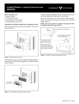
A Defiant leaves the factory with the combustor in-
stalled.
In the United States, it is against the law to operate this
wood heater in a manner inconsistent with operating
instructions in this manual, or if the catalytic combustor
is deactivated or removed. The components of the cata-
lytic combustion system in your Defiant work together to
produce optimum conditions for secondary combustion.
When the damper is closed, smoke travels through the
catalytic element, which causes ignition of smoke at
temperatures of 60°-315° C (500°-600° F), half the
temperature normally required for unaided secondary
combustion.
The catalytic element is a ceramic “honeycomb” coated
with the catalytic material. The element is located in the
secondary combustion chamber, molded from a special
high-temperature insulating refractory material. The
chamber provides the correct environment necessary
for secondary combustion of the fuel (smoke).
Closing the damper exposes the smoke to the combus-
tor. If the combustor is at least 315° C (600° F), it will
begin to burn the smoke.
Closing the stove damper may also reduce the draft, so
to avoid putting out the fire or deactivating the combus-
tor, close the damper only when a fire is well-estab-
lished and the chimney is thoroughly warmed. When
starting a fire, wait until the fire is well established and
there is an ember bed of at least 76-10 mm (3-4”)
before closing the damper.
Never kindle a fire with colored paper or paper that
has colored ink or a glossy surface, and never burn
treated wood, garbage, solvents, or trash. All of these
may poison the catalyst and prevent it from operating
properly. Never burn cardboard or loose paper except
for kindling purposes. Never burn coal; doing so can
produce soot or large flakes of char or fly ash that can
coat the combustor and cause smoke to spill into the
room. Coal smoke also can poison the catalyst so that it
won’t operate properly.
In general, the fire must be sufficiently well-established
to ensure that catalytic activity is initiated. When first
starting a fire, a medium- to high- firing rate must be
maintained until the stove, catalyst, and fuel are all
stabilized at the proper operating temperatures, and the
chimney is warmed.
Even though it is possible for the fire to get quite hot
within a few minutes after a fire is started, the combus-
tor may stop working or the fire may go out if the fire
dies down immediately as a result of the damper being
closed. Once the combustor starts working, heat gener-
ated by burning the smoke will keep it working.
things as the length, type, and location of the chimney,
local geography, nearby obstructions, and other factors.
See Page 0 for details on how the installation affects
performance.
Too much draft may cause excessive temperatures in
the Defiant, and could even damage the combustor.
On the other hand, too little draft can cause backpuffing
into the room and/or the “plugging” of the chimney or
combustor.
How do you know if your draft is excessively high or
low? Symptoms of too much draft include an uncontrol-
lable burn or a glowing-red stove part. Signs of weak
draft are smoke leaking into the room through the stove
or chimney connector joints, low heat, and dirty glass.
In some newer homes that are well-insulated and
weather-tight, poor draft may result from insufficient air
in the house. In such instances, an open window near
the stove on the windward side of the house will provide
the fresh air needed.
In some areas provisions for outside combustion air
are required. Refer to section of Document J which
requires an outside air vent for appliances with power
outputs over 5 kW. Always refer to national and local
codes to determine your specific requirements.
With an optional outside air adapter, No. 1904, your
Defiant will accept a duct to deliver outside air for com-
bustion.
When first using the stove, keep track of the air control
settings. You will quickly find that a specific setting will
give you a fixed amount of heat. It may take a week or
two to determine the amount of heat and the length of
burn you should expect from various settings.
Most installations do not require a large amount of
combustion air, especially if adequate draft is available.
Use the following air control settings as a starting point
to help determine the best settings for your installation.
Each is described as a fraction of the total distance the
lever may be moved from right to left.
(Refer to Figure 1, Page 14)
Low From far right to 1/3 the distance
to left
Medium From 1/3 to /3 the distance
to left
High From /3 the distance
to left, to far left

17
Defiant® Woodburning Stove
30003841
To determine whether the combustor is operating, ob-
serve the amount of smoke leaving the chimney when
the damper is activated and when it is not. This proce-
dure is described on Page 9.
Avoid using a full load of very dry wood in the firebox.
This may result in continuous very high temperatures
in the secondary combustion area and damage the
combustor. Wood which has been split, and stored un-
der cover for more than 18 months may be considered
very dry. If you must burn extra-dry wood, mix it with
greener wood for a longer fire and less stress on the
combustor. Also, do not use a full load of dry slab wood
or scrap wood. For long burns, use a mix of dry and
moderately dry wood.
Cast iron is extremely strong, but it can be broken with
a sharp blow from a hammer or from the thermal shock
of rapid and extreme temperature change.
The cast plates expand and contract with changes in
temperature. When you first begin using your Defiant,
minimize thermal stress by letting the plates adjust
gradually during three or four initial break-in fires follow-
ing Steps 1-3 below.
Burn only solid wood in the Defiant, and burn it directly
on the grate. Do not elevate the fuel. Do not burn coal
or other fuels.
The damper must be open when starting a fire or when
refueling.
1. Open the stove damper, and open the primary air
control fully.
. Place several sheets of crumpled newspaper in the
stove. Do NOT use glossy advertisements or colored
paper, as they can poison the catalyst. Place on the
paper six or eight pieces of dry kindling split to a finger-
width size, and on the kindling lay two or three larger
sticks of split dry wood approximately 5-50 mm (1-”)
in diameter. (Fig. 6)
Also, never use gasoline-type lantern fuel, kerosene,
charcoal lighter fluid, or similar liquids to start or “fresh-
en up” a fire. Keep all such liquids well away from the
Defiant while it is in use.
Light the newspaper and close the door. Gradually
build up the fire by adding a few 76-17 mm (3-5”) di-
ameter splits.
During the break-in fires, do not let the stove get hot-
ter than 60° C (500° F) as measured on an optional
ST263
starting a fire
12/99
ST63
Start the fire with newspaper and dry kindling.
stove-top thermometer. Adjust the air control lever as
necessary to control the fire.
Some odor from the stove’s hot metal, the paint, and
the cement is normal for the first few fires.
Some chimneys must be “primed,” or warmed
up, before they will draw sufficiently to start a fire. To
correct this situation, roll up a couple pieces of news-
paper, place them on top of the kindling and toward
the back of the stove, light them, and close the doors.
This will encourage the smoke to rise rapidly, making it
easier to establish a good draft.
Once the draft is established, open the front door and
light the rest of the fuel from the bottom. Do not light
the main bed of fuel until the chimney begins drawing,
and repeat the procedure as often as necessary if the
initial attempt is unsuccessful.
us-
ing Steps 1-3, continue to build the fire gradually. Add
larger wood with a diameter of 76-10 mm (3-4”100).
Continue adding split logs of this size to the briskly-
burning fire until there is a glowing ember bed at least
76 mm (3”) deep. (Fig. 7) A good ember bed is neces-
sary for proper functioning of the catalytic system and
may take an hour or more to establish.
Close the damper when the griddle temperature
reaches 30° C (450° F).
Adjust the air control for your desired heat output.
Stove installations vary widely, and the operat-
ing guidance given here is only a starting point . The
draft management information on Page 0 will explain
in detail how the features of your installation may help
or hinder good draft, and how you may need to vary
your firing technique if your installation doesn’t encour-
age a good draft.
When reloading, best results will be achieved if you first
de-ash the stove by stirring the fuel bed to allow ash to
fall through the grate into the ash pan.

18
Defiant® Woodburning Stove
30003841
ST264
good fire
12/99
ST64
Add larger pieces of wood as the fire begins to burn
well.
ST264a
add wood fire
11/00
ST64a
Add full size logs after the ember bed is 3” (75mm)
deep.
4. Close the damper.
5. When the surface temperature reaches 30° C
(450° F), adjust the air control for the amount of heat
you desire.
If the remaining charcoal bed is relatively thick
and if your fuel is well seasoned, it is possible to add
fresh fuel (smaller pieces first), close the door and
damper, and reset the primary air thermostat for the
desired heat output.
Overfiring may
cause a house fire, or can result in permanent dam-
age to the stove and to the catalytic combustor. If any
part of the Defiant other than the baffle and/or catalytic
combustor glows, you are overfiring.
The throat is made of a special cast iron which can
withstand higher temperatures than most other parts
of your stove. It protects the catalytic element from
direct flame impingement, which can shorten the
catalyst’s life. Since the throat is in the direct path of
flame between the firebox and the catalyst, it reaches
higher temperatures than other firebox parts, and it may
glow at times. If it does glow, you will see this directly
through the front doors. The glow is normal and does
not indicate a problem.
At times you may see a glow from the catalyst shining
through the ports of the throat. This is also normal and
does not indicate a problem. The catalytic element,
located below and behind the throat, can glow at high
temperatures. This is also normal. However, the ele-
ment can be active and operate properly without glow-
ing. The lack of a glow does not indicate that the cata-
lyst isn’t working. Note that the catalyst is most likely to
glow at its higher temperatures, which it reaches when
the firebox is in its lower range - the catalyst is an after-
burner, and the more waste fuel there is in the smoke,
the hotter the catalyst gets.
We strongly advise the use of a stove-top thermometer
as a guide to stove performance. Normal operating
temperatures are between 0° C (450° F) and 370° C
(700° F). Lower temperatures can indicate incomplete
combustion and weak draft; higher temperatures can
shorten the life of the castings.
Routine ash removal is important for ease of main-
tenance, and is important for the stove’s durability.
Remove ash before it reaches the top of the ash pan.
Check the level at least once a day. Every few days,
clear any ash from the outer edges of the firebox. Most
of the ash will fall through the grate. Slice or stir the
ash with a shovel or poker so that it falls through the
grate slots.
Do not break the charcoal into very small pieces or
pound or compress the charcoal bed.
It is important that air can circulate through the charcoal
bed during the burn. Larger pieces of charcoal allow
more air to circulate under the wood, resulting in the
fire reviving more quickly. (Fig. 8)
For best results when refueling, wear long-cuffed stove
gloves to protect your hands and forearms, add fuel
while the stove still has plenty of glowing embers to
re-kindle the fire, and include some smaller pieces of
wood in the new fuel load to help the stove regain its
operating temperature quickly. Use this sequence as a
guide to successful refueling:
Door handles can be hot. A glove has been
included with your stove. We recommend using this
glove whenever operating door or damper controls, and
especially when operating the top griddle.
1. Open the damper.
. De-ash the stove as described above. Open the
ashdoor and check the level of ash in the ash pan.
Empty the pan if necessary and replace it in the
stove. Close the ash door.
3. Open the griddle, load the wood (smaller pieces
first), and close the griddle.

19
Defiant® Woodburning Stove
30003841
Check the level of ash in the ash pan
before reloading the stove. If the ash level is close to
the top edge of the pan, empty the pan according to this
procedure:
• Open the damper.
• Open the griddle or front doors, and use a shovel or
poker to stir excess ash through the ash slots in the
grate down into the ash pan.
• Close the griddle or doors, and unlatch the ash door.
(Fig. 9) It will pivot, swinging the ash pan out of the
stove.
• Slide the cover onto the pan, making sure it is se-
curely closed. (Fig. 30)
• Remove the ash pan, making sure to keep it level.
• To keep the cover from sliding off and to keep ash
from falling on the floor, do not tilt the ash pan for-
ward.
• If the stove is in operation, close the ash door while
disposing of the ash. You may need to lift the latch
end of the door slightly to align the latch with the
mating part on the stove bottom.
• Properly dispose of the ash in a metal container with
a tight-fitting lid. Store the container outdoors away
from all combustible material.
• Return the ash pan to its original position in the
stove, and close and latch the ash door. (Fig. 31)
• Do not operate the stove with the ash door open.
This will result in over-firing, and could cause dam-
age to the stove, void the warranty, or even lead to a
house fire.
Empty the ash pan regularly, typically every one to
three days. The frequency will vary depending on how
you operate your Defiant: ash will accumulate faster at
higher heat outputs.
Remove ash frequently and place it outdoors in a
metal container with a tight-fitting lid. Place the closed
container of ash on a noncombustible floor or on the
ST545
ashdoor
11/00
ST545
Turn the ashdoor handle clockwise to open and coun-
terclockwise to close.
Open
Close
ST566
Remove
Ashpan
12/00
ST566
Be sure the cover is securely attached before remov-
ing the ash pan.
ground, well away from all combustible materials, pend-
ing final disposal. If the ash is disposed of by burial in
soil or otherwise locally dispersed, it should be kept in
the closed container until all cinders have thoroughly
cooled.
You can use wood ash as a garden fertilizer.
Never use your household or shop vacuum
cleaner to remove ash from the stove; always remove
and dispose of the ash properly.

0
Defiant® Woodburning Stove
30003841
A stove is part of a system, which includes the chimney,
the operator, the fuel, and the home. The other parts of
the system will affect how well the stove works. When
there is a good match between all the parts, the system
works well.
Wood stove or insert operation depends on natural
(unforced) draft. Natural draft occurs when the smoke
is hotter (and therefore lighter) than the outdoor air at
the top of the chimney. The bigger the temperature
difference, the stronger the draft. As the smoke rises
from the chimney it provides suction or ‘draw’ that pulls
air into the stove for combustion. A slow, lazy fire with
the stove’s air inlets fully open indicates a weak draft.
A brisk fire, supported only by air entering the stove
through the normal inlets, indicates a good draft. The
stove’s air inlets are passive; they regulate how much
air can enter the stove, but they don’t move air into it.
Depending on the features of your installation - steel
or masonry chimney, inside or outside the house,
matched to the stove’s outlet or oversized - your
system may warm up quickly, or it may take a while to
warm up and operate well. With an ‘airtight’ stove, one
which restricts the amount of air getting into the firebox,
the chimney must keep the smoke warm all the way to
the outdoors in order for the stove to work well. Some
chimneys do this better than others. Here’s a list of
features and their effects.
Masonry is a traditional material for chimneys, but it
can perform poorly when it serves an ‘airtight’ stove.
Masonry is a very effective ‘heat sink’ - it absorbs a lot
of heat. It can cool the smoke enough to diminish draft.
The bigger the chimney, the longer it takes to warm up.
It’s often very difficult to warm up an outdoor masonry
chimney, especially an oversized one, and keep it
warm enough to maintain an adequate draft.
Most factory-made steel chimneys have a layer of
insulation around the inner flue. This insulation keeps
the smoke warm. The insulation is less dense than ma-
sonry, so a steel chimney warms up more quickly than
a masonry chimney. Steel doesn’t have the good looks
of masonry, but it performs much better.
Because the chimney must keep the smoke warm, it’s
best to locate it inside the house. This uses the house
as insulation for the flue and allows some heat release
into the home. An indoor chimney won’t lose its heat
to the outdoors, so it takes less heat from the stove to
heat it up and keep it warm.
The common wisdom tells us that a taller flue draws
better than a short one. This isn’t necessarily so. If a
chimney is tall enough to meet the safety requirements
of the /3/10 foot rule, then adding more height isn’t the
right answer to a draft problem. In fact it could make the
problem worse, by adding more mass to the chimney
system, which the smoke must warm up, at the far end
from the heat source (the stove). Don’t make a chimney
taller unless you must to meet the safety rules, or un-
less there’s some nearby feature causing a downdraft.
Even then, there are downdraft-preventing chimney
caps available, which are probably the smarter choice.
The inside size of a chimney for an ‘airtight’ stove
should match the size of the stove’s flue outlet. When
a chimney serves an airtight stove, more is not better;
in fact, it can be a disadvantage. Hot gases lose heat
through expansion; if we vent a stove with a six-inch
flue collar (8 square inch area) into a 10 x 10” flue,
the gases expand to over three times their original size.
This cools the gases, which weakens draft strength. If
an oversized flue is also outside the house, the heat it
absorbs gets transferred to the outdoor air and the flue
usually stays cool.
It’s common for a masonry flue, especially one serving
a fireplace, to be oversized for the stove. It can take
quite a while to warm up such a flue, and the results
can be disappointing. The best solution to an oversized
flue is an insulated steel chimney liner, the same diam-
eter as the stove or insert’s flue outlet; the liner keeps
the smoke warm, and the result is a stronger draft. An
uninsulated liner is a second choice - the liner keeps
the smoke restricted to its original size, but the smoke
still must warm up the air around the liner. This makes
the warm-up process take longer.
Every turn the smoke must take as it travels to the
chimney top will slow it down. The ideal pipe and chim-
ney layout is straight up from the stove, to a completely
straight chimney. If you’re starting from scratch, use this
layout if possible. If the stovepipe must elbow to enter a
chimney, locate the thimble about midway between the
stove top and the ceiling. This achieves several goals:
it lets the smoke speed up before it must turn, it leaves
some pipe in the room for heat transfer, and it gives you
long-term flexibility for installing a different stove without
relocating the thimble.
/