Vermont Castings FREESTANDING WOODBURNER Specification

Category
Stoves
Type
Specification

This manual is also suitable for

0956
Encore Cover
2/01
Homeowners
Installation and
Operating Manual







2000956 9/10 Rev. 29


Model 2550
2
Encore
®
Woodburning Stove
2000956
Congratulations on your choice of a Vermont Castings Encore. With this purchase you have made a commitment to
make the hearth a place of warmth, beauty, and comfort in your home. At MHSC, we share that joy and appreciation
for the hearth. You may be assured that your cast-iron Vermont Castings stove has been made with the utmost care
and will provide you with many years of service.
As you become acquainted with your new stove or fireplace, you will find that its visual appearance is matched by its
functionality, due to cast iron’s unique capability to absorb and radiate heat.
Also, MHSC units are among the cleanest-burning wood stoves and fireplaces available today. As an owner of a
Vermont Castings stove, you make a strong statement for pollution-free energy. Clean burning, however, depends on
both the manufacturer and the operator. Please read this manual carefully to understand how to properly operate and
maintain your stove or fireplace.
At MHSC, we are equally committed to your satisfaction as a customer. That is why we maintain an exclusive network
of the finest dealers in the industry. Our dealers are chosen for their expertise and dedication to customer service.
They are factory-trained and knowledgeable about every MHSC product. Feel free to contact your Authorized Vermont
Castings Dealer anytime you have a particular question about your stove or its performance.
This manual contains valuable instructions on the installation and operation of your Vermont Castings stove. It also
contains useful information on maintenance and assembly of this product. We urge you to read the manual thoroughly
and to keep it as a reference.
Sincerely,
All of us at MHSC

This manual describes the installation, operation,
and maintenance of the Vermont Castings Encore
Model 2550 catalytic-equipped wood burning heater.
This heater meets the U.S. Environmental Protection
Agency’s emission limits for wood heaters sold on or
after July 1, 1990. Under specific test conditions this
heater has been shown to deliver heat at rates ranging
from 8,700 to 41,700 Btu/hr.
The Encore Model #2550 is listed by OMNI-Test Labo-
ratories of Portland, Oregon. The test standards are
ANSI/UL-1482 and ANSI/UL-737 for the United States,
and ULC S627 for Canada. The Encore is listed for
burning wood. Do not burn other fuels. The Encore
is listed and approved for use in mobile homes in the
United States only when installed with Vermont Cast-
ings Mobile Home Kit #3251.
We recommend that you hire a professional installer
certified by the Wood Heat Education and Research
Foundation (WHERF) or the Wood Energy Techni-
cal Training (WETT) to install your stove, or to advise
you on the installation should you attempt to install it
yourself.
Please read this entire manual before you install and
use your new stove. Failure to follow instructions may
result in property damage, bodily injury, or even death.

Warming Shelves
#1560 Classic Black #1558 Vt. Classic Green
#1553 Brown Majolica #1565 Bordeaux
#1555 Biscuit #1567 Midnight Blue
#1557 Ebony
# 0127 Sparkscreen
# 0173 Rear Heat Shield
# 3257 Outside Air Adapter
# 3251 Mobile Home Kit
# 0191 Heat shields for the chimney connector
- Matching porcelain stovepipe
Specifications ................................. 3
Installation ...................................... 4
Assembly ...................................... 18
Operation ...................................... 19
Maintenance ................................. 27
Appendix: Catalytic Combustor .... 33
Replacement Parts ....................... 34

 Fuels used in gas, wood-
burning or oil fired appliances, and the products of
combustion of such fuels, contain chemicals known to
the State of California to cause cancer, birth defects
and other reproductive harm.
California Health & Safety Code Sec. 25249.6
3
Encore
®
Woodburning Stove
2000956

2"
(50mm)
2556M"
(640mm)
Top exit
flue collar
height
27"
(685mm)
25(6"
(660mm)
1856O"
(470mm)
76"
(190mm)
27"
(685mm)
2256O"
(570mm)
1556O"
(390mm)
5"
(130mm)
2(6" (75mm)
236"
(595mm)
556M"
(135mm)
15"
(380mm)
24"
(610mm)
356M"
(83mm)
27"
(690mm)
216"
(545mm)
18"
(460mm)

Encore 2550
dimensions
 Encore dimensions.
Drawings Not to Scale
Range of heat output .................8,700-41,700 Btu’s/Hr*
Maximum heat output ........................ 47,000 Btu’s/Hr**
EPA emissions ratings, g/h, catalytic .......................1.6*
Area heated*** ............... Up to 1900 sq. ft. (175 sq. m.)
Fuel size/type ...................... 18-20” (450-500 mm) logs
Fuel capacity ........................................... 40 lbs. (18kg)
Loading ....................................................... Front or top
Chimney connector:
for 8” flue collar ....................... 8” (203 mm) diameter
for 6” flue collar ....................... 6” (152 mm) diameter
Chimney flue size:
for 8” flue collar .......................8” (203 mm) minimum
for 6” flue collar .......................6” (152 mm) minimum
Flue exit position........................ Reversible, top or rear
Primary air ... Manually set, thermostatically maintained
Secondary air .........................................Self-regulating
Ash handling system ..................... Removable ash pan
Glass panel.......................... High-temperature ceramic
Weight ................................................. 350 lbs. (159kg)
Width (leg-to-leg) ..................................... 27” (685 mm)
Depth (leg-to-leg)..................................... 15” (380 mm)
Height to top of flue collar, (6” or 8”)
Top exit .............................................. 25¹⁄₄” (640 mm)
Rear exit ............................................ 26¹⁄₂” (675 mm)
*Under specific conditions used during EPA emissions
testing.
**These values are based on operation in building
code-conforming homes under typical winter climate
conditions in New England. If your home is of nonstan-
dard construction (e.g. unusually well-insulated, not in-
sulated, built underground, etc.) or if you live in a more
severe or more temperate climate, these figures may
not apply. Since so many variables affect performance,
consult your Vermont Castings’ Authorized Dealer to
determine realistic expectations for your home.
4
Encore
®
Woodburning Stove
2000956







Before you begin an installation, be sure that:
Your stove and chimney connector will be far
enough from combustible materials to meet all
clearance requirements.
The floor protector is large enough and is con-
structed properly to meet all requirements.
You have all necessary permits from local au-
thorities.
Your local building official is the final authority for ap-
proving your installation as safe and determining that it
meets local and state codes.
The metal label permanently attached to the back of
every Vermont Castings’ stove indicates the stove has
been tested to current UL and ULC standards, and
gives the name of the testing laboratory. Clearance
and installation information also is printed on the label.
When the stove is installed according to the information
both on the label and in this manual, local authorities
in most cases will accept the label as evidence that the
installation meets codes and can be approved.
However, codes vary in different areas. Before starting
the installation, review your plans with the local building
authority. Your local dealer can provide any additional
information needed.
For any unresolved installation issues, refer to the
National Fire Protection Association’s publication
ANSI/NFPA 211 Standard for Chimneys, Fireplaces,
Vents and Solid Fuel Burning Appliances. For Canada,
the equivalent publication is CSA CAN-B365 Installation
Code for Solid Fuel Burning Appliances and Equipment.
These standards are the basis for many national codes.
They are nationally recognized and are accepted by
most local authorities. Your local dealer or your local
building official may have a copy of these regulations.









In some modern, super-insulated homes, there is
inadequate air for combustion because of insufficient
air infiltration into the building. Such air enters a home
through unsealed cracks and openings. Exhaust fans
for kitchen or bath can compete with the stove for avail-
able air and compound the problem.
When poor draft is caused by a low infiltration rate,
opening a ground floor window on the windward side
of the house and in the vicinity of the stove will usually
alleviate the problem.
Another solution is to install a permanent outside air
supply to the stove and/or room. In fact, bringing air
for combustion from outside the home directly to the
air inlet of the stove is required for new construction in
some areas.
Pressure variations within the house do not affect a
stove equipped with an outside air supply, and im-
proved stove performance often results. An Outside Air
Adapter Kit for the Encore is available from your local
Vermont Castings dealer.

Altitude affects chimney performance. When using a
6” flue collar on the Encore, refer to Figure 2 for sug-
gested chimney heights at various altitudes. Chimney
height should be measured from the flue collar to the
top of the chimney. The recommended minimum chim-
ney height is 16’ (4.9m).
30
25
20
15
0 2000 4000 6000 8000 10000 12000
Height
Altitude
ST491
Defiant
chimney height
11/2/00 djt
ST491
 Chimney height requirements for Encore when
equipped with a 6” chimney.
5
Encore
®
Woodburning Stove
2000956

You must connect the Encore to a code-approved
masonry chimney with a flue liner, to a relined masonry
chimney that meets local codes, or to a prefabricated
metal chimney that complies with the requirements
for Type HT chimneys in the Standard for Chimneys,
Factory-Built, Residential Type and Building Heating
Appliance, UL 103. (Fig. 3) The chimney and chimney
connector must be in good condition and kept clean.
ST241
chimney types
12/13/99 djt
ST241
A tile-lined
masonry
chimney
A prefabricated double-
wall insulated chimney
 Approved chimney types.
If you use an existing masonry chimney, it must be
inspected to ensure it is in a safe condition before the
stove is installed. Your local professional chimney
sweep, building inspector, or fire department official will
be able to inspect the chimney or provide a referral to
someone who can.
The chimney should extend at least 3’ (914 mm) above
the highest point where it passes through a roof, and at
least 2’ (610 mm) higher than any portion of a building
within 10’ (3 m). (Fig. 4)
For proper draft and good performance, any chimney
used with an Encore should extend at least 16’ (5 m)
above the flue collar of the stove.

An inspection of the chimney must confirm that it has
a lining. Do not use an unlined chimney. The chimney
should have no cracks, loose mortar, other signs of
deterioration, and blockage. Repair any defects before
the chimney is used with your stove.
Unused openings in an existing masonry chimney must
be sealed with masonry to the thickness of the chimney
wall, and the chimney liner should be repaired. Open-
ings sealed with pie plates or wallpaper are a hazard
and should be sealed with mortar or refractory cement.
In the event of a chimney fire, flames and smoke may
be forced out of these unused thimbles.
The chimney should be thoroughly cleaned before use.
A newly-built masonry chimney must conform to the
standards of your local building code or, in the absence
of a local code, to a recognized national code. Masonry
chimneys must be lined, either with code-approved
masonry or pre-cast refractory tiles, stainless steel
pipe, or a code-approved, “poured-in-place” liner. The
chimney’s clean-out door must seal tightly.

A prefabricated metal chimney must be one tested and
listed for use with solid-fuel burning appliances to the
High-Temperature (H.T.) Chimney Standard UL-103-
1985 (2100°F) for the United States, and High Temper-
ature (650°C) Standard ULC S-629 for Canada.



An Encore with an 8” (203 mm) flue collar is approved
for venting into a masonry chimney with a nominal flue
size of 8” x 8” (203 x 203 mm) or 8” x 12” (203 x
305 mm), and into a round flue with nominal flue size of
8” (203 mm). An Encore with a 6” (152 mm) flue collar
is approved for venting into a masonry chimney with a
nominal flue size of 8” x 8” (203 x 203 mm), and into a
round flue with nominal flue of 6” (152 mm).



Whatever the flue collar size, an Encore may be vented
into larger chimneys as well. However, chimneys with
liners larger than 8” x 12” (203 x 305mm) may experi-
ence rapid cooling of smoke and reduction in draft, es-
pecially if the chimneys are located outside the home.
These large chimneys may need to be insulated or
have their flues relined for proper stove performance.
Accessories to help make the connection between
stainless steel chimney liners and your Encore are
available through your local dealer.
2' Min.
2' Min.
3'
Min.
0 To 10'
3'
Min.
0 To 10'
AC617
RLTSKC8
2/11/98
Reference
Point
AC617
 The 2’-3’-10’ Chimney Rule.
6
Encore
®
Woodburning Stove
2000956

A chimney connector is the double-wall or single-wall
pipe that connects the stove to the chimney. The chim-
ney itself is the masonry or prefabricated structure that
encloses the flue. Chimney connectors are used only to
connect the stove to the chimney, as in Figure 5.
Double-wall connectors must be tested and listed for
use with solid-fuel burning appliances. Single-wall con-
nectors should be made of 24 gauge or heavier steel.
Do not use galvanized connector; it cannot withstand
the high temperatures that can be reached by smoke
and exhaust gases, and may release toxic fumes under
high heat. The connector may be 6” (152 mm) or 8 “
(203 mm) in diameter.
If possible, do not pass the chimney connector through
a combustible wall or ceiling. If passage through a com-
bustible wall is unavoidable, refer to the section on Wall
Pass-Throughs. Do not pass the connector through an
attic, a closet or similar concealed space. The whole
connector should be exposed and accessible for in-
spection and cleaning.
In horizontal runs of chimney connector, maintain a dis-
tance of 24” (610 mm) from the ceiling. Keep it as short
and direct as possible, with no more than two 90° turns.
Slope horizontal runs of connector upward 1/4” per foot
(6 mm per meter) going from the stove toward the chim-
ney. The recommended maximum length of a horizontal
run is 3’ (1 m), and the total length should be no longer
than 8’ (2.4 m). In cathedral ceiling installations, extend
the prefabricated chimney downward to within 8’ (2.4 m)
of the stove.



Information on assembling and installing double-wall
connectors is provided by the manufacturer of the
double-wall pipe. Follow the manufacturer’s instructions
exactly as you assemble the connector and attach it to
the stove and chimney. Using chimneys and connectors
from the same manufacturer makes the assembly and
installation straightforward.
For installations using double-wall connectors,
minimum clearances must conform to the listed clear-
ances in the clearance chart on Page 14.
If the Encore is equipped with the 8” flue collar, an oval-
to-round adapter will be needed. Double-wall oval-to-
round adapters are available from some manufacturers.
Your local dealer can help you select the right connec-
tor.

Begin assembly at the flue collar of the stove. Insert
the first crimped end into the stove’s flue collar, and
keep each crimped end pointing toward the stove.
(Fig. 5)Using the holes in the flue collar as guides,
drill 1/8” (3mm) holes in the bottom of the first sec-
tion of chimney connector and secure it to the flue
collar with three #10 x 1/2” sheet metal screws.
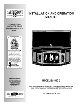
Secure each joint between sections of chimney
connector, including
telescoping joints, with at
least three (3) sheet metal
screws. The pre-drilled
holes in the top of each
section of chimney con-
nector serve as guides
when you drill 1/8” (3mm)
holes in the bottom of the
next section.
Secure the chimney con-
nector to the chimney.
Instructions for various
installations follow.
Be sure the installed stove
and chimney connector are correct distances from
nearby combustible materials.
 Special slip pipes and thimble sleeves that form
telescoping joints between sections of chimney con-
nector are available to simplify installations. They often
eliminate the need to cut individual connector sections.
Consult your local dealer about these special pieces.


Follow the installation instructions of the chimney
manufacturer exactly as you install the chimney. The
manufacturer of the chimney will supply the acces-
sories to support the chimney, either from the roof of
the house, at the ceiling of the room where the stove is
installed, or from an exterior wall.
Special adapters are available from your local dealer
to make the connection between the prefabricated
chimney and the chimney connector. The top of such
adapters attaches directly to the chimney or to the
chimney’s ceiling support package, while the bottom of
the adapter is screwed to the chimney connector.
These adapters are designed so the top end will fit
outside the inner wall of the chimney, and the bottom
end will fit inside the first section of chimney connector.
When assembled in this way, any soot or creosote fall-
ing from the inner walls of the chimney will stay inside
the chimney connector.
ST242
Chimney connector
12/13/99 djt
 the crimped end
of the connector points
toward stove.
7
Encore
®
Woodburning Stove
2000956
ST492
Defiant
freestanding
installation
11/00
Chimney
Elbow
Slip Pipe
Standard
Connector
Oval to
Round Adapter
Flue Collar
Thimble
Flue Liner
Flue
ST492
 An exploded view of the chimney connection in a free-
standing masonry installation.


Both freestanding masonry chimneys and fireplace
masonry chimneys may be used for your installation.

If the chimney connector must pass through a combus-
tible wall to reach the chimney, follow the recommenda-
tions in the Wall Pass-Through section that follows.
The opening through the chimney wall to the flue
(the “breech”) must be lined with either a ceramic or
metal cylinder, called the “thimble”, which is cemented
securely in place. Most chimney breeches incorporate
thimbles, but the fit must be snug and the joint between
the thimble and the chimney wall must be cemented
firmly.
A special piece called the “thimble sleeve,” slightly
smaller in diameter than standard connectors and
most thimbles, will facilitate the removal of the chimney
connector system for inspection and cleaning. Thimble
sleeves should be available from your local dealer.
To install a thimble sleeve, slide it into the breech until
it is flush with the inner flue wall. Do not extend it into
the actual flue passage, as this could interfere with the
draft.
ST243
thinble connection
12/13/99 djt
Thimble Sleeve
Chimney Connector
Flue
Keep
sleeve
end flush
with flue
tile
ST243
 The thimble, made of either ceramic or metal, must be
cemented securely in place.
The thimble sleeve should protrude 1-2” (25-50mm) into
the room. (Fig. 7) Use furnace cement and thin gasket-
ing to seal the sleeve in place in the thimble. Secure
the chimney connector to the outer end of the sleeve
with sheet metal screws.
Without a thimble, a suitable length of chimney con-
nector can be extended through the breech to the inner
face of the flue liner, and cemented securely in place.
Additional pieces of connector are then attached with
sheet metal screws.

The chimney connector may be connected to the
chimney above the fireplace opening or through the
fireplace.

The Encore may be connected to a chimney above
a fireplace opening. (Fig. 8) In such installations, the
stove is positioned on the hearth in front of the fireplace
and the chimney connector rises from the stove top and
then angles ninety degrees back into the chimney. The
chimney liner should extend to the point at which the
chimney connector enters the chimney.
If the chimney connector from your installation enters
the chimney above a fireplace, follow all the guidelines
mentioned above for freestanding installations. In addi-
tion, give special consideration to the following points:
Check the clearance between the stove and the
chimney connector, and any combustible trim or the
mantel. Use the necessary combination of mantel, trim,
and connector heat shields to achieve the required
clearances.
Check the clearance between the chimney con-
nector and the ceiling. If no heat shields are used, the
clearance should be at least 24” (610 mm). To find out
how much this clearance may be reduced with heat
shields, refer to the clearance chart on Page 14.
8
Encore
®
Woodburning Stove
2000956
The fireplace damper must be sealed to prevent
room air from escaping up the flue. However, it must be
possible to re-open the damper to inspect or clean the
chimney.
* Check
These Clear-
ances
ST244
Plymouth
fplc over mantel
12/99
*
*
Chimney
Connector Shields
Mantel
Seal this off
ST244
Fig. 8 In this installation, the chimney connector is attached
to the chimney above the fireplace opening.

If your fireplace opening height is at least 26¹⁄₂" (675 mm),
you may install an Encore through the opening using a
“positive connection” kit, available from your local dealer.
These positive connection kits ensure a tight fit between
the stove flue collar and the chimney flue. (Fig. 9)
Fireplace installations, whether connected to the flue
above or through the fireplace opening, have special
clearance requirements to adjacent trim and the mantel.
You’ll find the required safe clearances for Encore fire-
place installations on Page 12.
Floor protection requirements also apply to fireplace
installations. This information is on Page 10.

Whenever possible, design your installation so the con-
nector does not pass through a combustible wall. If you
are considering a wall pass-through in your installation,
check with your building inspector before you begin.
Also, check with the chimney connector manufacturer
for any specific requirements.
Accessories are available for use as wall pass-
throughs. If using one of these, make sure it has been
tested and listed for use as a wall pass-through.
Flexible Connector
Mantel Shield
Fireplace Adapter
Kit “Positive Con-
nection”
ST245
 In this installation, the chimney connector enters the
firepalce opening and then connects to the chimney.
 the National Fire Protection As-
sociation (NFPA) has established guidelines for passing
chimney connectors through combustible walls. Many
building code inspectors follow these guidelines when
approving installations.
Figure 10 shows one NFPA-recommended method.
All combustible material in the wall is cut away from
the single-wall connector to provide the required 12”
(305mm) clearance. Any material used to close up the
opening must be noncombustible.
Three other methods are also approved by the NFPA:
Using a section of double-wall chimney with a 9”
(229 mm) clearance to combustibles.
Placing a section of chimney connector inside
a ventilated thimble, which in turn is separated from
combustibles by 6” (152 mm) of fiberglass insulating
material.
Placing a section of chimney connector inside a
section of 9” (230 mm) diameter, solid-insulated, facto-
ry-built chimney, with 2” (51 mm) of air space between
the chimney section and combustibles.
The Canadian Standards Association has
established different guidelines. Figure 10 shows one
method, in which all combustible material in the wall is
cut away to provide the required 18” (457 mm) clear-
ance for the connector. The resulting space must re-
main empty. A flush-mounted sheet metal cover may be
used on one side only. If covers must be used on both
sides, each cover must be mounted on noncombustible
spacers at least 1” (25 mm) clear of the wall.
9
Encore
®
Woodburning Stove
2000956
D
E
F
I
A
N
T
ST493
Brick pass thru
11/00
Wall Stud
Chimney
Connector
12” Noncombustible
Material
Floor Pro-
tection
ST493
 An approved wall pass-through for the United States.
Your local dealer or your local building inspector can
provide details for other approved methods of passing
a chimney connector through a combustible wall in your
area. In Canada, this type of installation must conform
to CAN/CSA-B365, Installation Code for Solid Fuel
Burning Appliances and Equipment.
 Do not vent your Encore into a factory-built
(zero-clearance) fireplace. These appliances and their
chimneys are specifically designed as a unit for use as
fireplaces. It may void the listing or be hazardous to
adapt them for any other use.
T
ST494
steel
wall pass thru
11/00
18” (460mm) clear
space all around
the pipe
ST494
 An approved wall pass-through for Canada.



A tremendous amount of heat radiates from the bottom
plate of your stove. The floor area directly under and
around the stove will require protection from radiant
heat as well as from stray sparks or embers that may
escape the firebox.
Heat protection is provided through the use of a Ver-
mont Castings Bottom Heat Shield #0164. Spark and
ember protection must be provided by a floor protector
constructed with noncombustible material as specified.
Most installations will require the bottom heat shield be
attached. Only when the stove is placed on a complete-
ly noncombustible surface such as unpainted concrete
over earth may it be used without the heat shield.
Even when the bottom heat shield is installed, you must
provide special protection to the floor beneath. For
installations with the heat shield attached, use a non-
combustible floor protector such as 1/4” nonasbestos
mineral board or equivalent, or 24 gauge sheet metal.
The floor protector may be covered with a noncombus-
tible decorative material if desired. Do not obstruct the
space under the heater.
Protection requirements vary somewhat between the
Untied States and Canada as follows:
the floor protector is required under
the stove and must extend at least 16” (not including
the ash lip) from the front of the stove (“F”, Fig. 12), and
at least 6” from the sides and rear. (“D” and “E”, Fig.
12) It must also extend under the chimney connector
and 2” to either side. (“C”, Fig. 12) For the 8” (203 mm)
connector, the protector must be a minimum of 12”
(305 mm) wide. For the 6” (152 mm) connector, the
protector must be 10” (254 mm) wide. The protector
must be centered under the connector.
To meet these requirements, a floor protector must be
at least 39” wide and 44” deep.
A noncombustible floor protector is required
under the stove as well. The floor protector must
extend 18” (457 mm) to the front (“F”, Fig. 12), and 8”
(203 mm) from the sides and rear. (“D” and “E”, Fig. 12)
To meet these requirements, a floor protector must be
at least 43” (1092 mm) wide and 48” (1219 mm) deep.
Floor protection also must extend under the chimney
connector and 2” (51 mm) to either side. (“C”, Fig. 12)
For the 8” (203 mm) connector, the protector must be
a minimum of 12” (305 mm) wide. For the 6” (152 mm)
connector, it must be at least 10” (254 mm) wide. The
protector must be centered under the connector.
10
Encore
®
Woodburning Stove
2000956

Do not assume that your fireplace hearth is completely
noncombustible.
Many fireplace hearths do not meet the “completely
noncombustible” requirement because the brick or
concrete in front of the fireplace opening is supported
by heavy wood framing. (Fig. 13) Because heat passes
through brick or concrete readily, it can easily pass
through to the wood. As a result, such fireplace hearths
can be a fire hazard and are considered a combustible
floor.
Keep in mind, also, that many raised hearths will extend
less than the required clearance from the front of the
heater when it is installed. In such cases, sufficient
floor protection as described above must be added in
front of the hearth to satisfy the minimum floor protector
requirement from the front of the stove: 16” (406mm)
from the front in the United States and 18” (459mm)
from the front in Canada.
Hearth rugs do not satisfy the requirements for floor
protection.
Fireplace installations also have special clearance
requirements to the side walls, side decorative trim, and
fireplace mantel. This information follows in the section
on Fireplace and Mantel Trim Shields.
ST247
Rear exit floor dgrm
12/14/99 djt
Wood framing requires pro-
tection from radiant heat
ST247e
Combustible supporting timbers may lie beneath
fireplace hearths, requiring additional floor protection.


Both a stove and its chimney connector radiate heat in
all directions when operating, and dangerous overheat-
ing of nearby combustible materials can occur if they
are too close to the heat. A safe installation requires
that adequate clearance be maintained between the
hot stove and its connector and nearby combustibles.
Clearance is the distance between either your stove
(measured from the bottom edge of the stove’s top
plate) or chimney connector, and nearby walls, floors,
the ceiling, and any other fixed combustible surface.
Your stove has special clearance requirements that
have been established after careful research and test-
ing to UL and ULC standards. These clearance require-
ments must be strictly observed.
In addition, furnishings and other combustible materi-
als must be kept away from the stove as well. In gen-
eral, a distance of 48” (1219mm) must be maintained
between the stove and moveable combustible items
such as drying clothes, furniture, newspapers, firewood,
etc. Keeping those clearance areas empty assures that
nearby surfaces and objects will not overheat.

Clearance requirements are established to meet every
installation possibility, and they involve the combination
of four basic variables:
 

 

 

 
D
E
A
B
A
E
C
ST500
Encore
floor protection
2/23/01
E
F
E
F
 
A. 39” 43” (1092 mm)
B. 44” 48” (1219 mm)
C. 12” 12” (305 mm) 8” Connector
10” 10” (255 mm) 10” Connector
D. 6” 8” (203 mm)
E. 6” 8” (203 mm)
F. 16” 18” (459 mm)
ST500
 Required floor protector dimensions for both top-and
rear-exiting stove.
11
Encore
®
Woodburning Stove
2000956
In general, the greatest clearance is required when you
place a stove and its connector with no heat shields
near a wall with no heat shield.
For example, when the Encore is installed parallel to
the rear wall and no shields are used, it must be at least
31” (787 mm) from the wall behind it and at least 24”
(610 mm) from walls on either side.
If the Encore is installed in a corner and no shields
are used, the corners of the stove must be at least 24”
(610 mm) from nearby walls.
The least clearance is required when both the stove
and its connector, as well as the wall, have heat
shields.
When shields are attached to the stove or chimney
connector, they are mounted 1” - 2” (25-51 mm) away
from the stove or connector surface on noncombustible
spacers. Air flowing between the stove (and/or chimney
connector) and nearby shields carries away heat. Do
not block the air flow by filling this empty space with any
insulating material.
The shiny shield surface facing the heat source must be
left unpainted, enabling it to reflect heat back towards
the stove or connector and away from the wall.
Clearances may be reduced only by means approved
by the regulatory authority, and in accordance with the
clearances listed in this manual.
Because of their restricted air flow and heat retention
characteristics, specific construction requirements and
special clearances apply to installations into alcoves.
Refer to the diagrams on Page 10, and contact your
Vermont Castings Dealer for details before beginning
an alcove installation.



One way to reduce clearances is with a wall shield
constructed of 24 gauge or heavier sheet metal, or of
another noncombustible material such as 1/2” (13 mm)
insulation board or common brick “laid on flat,” with the
3¹⁄₂" (90 mm) side down.
Shields must be spaced out from the combustible
surface 1" (25 mm) on noncombustible spacers, as in
Figure 13. The spacers should not be directly behind
the stove or chimney connector.
Air must be able to flow between the wall and the
shield. At least 50% of the bottom 1" (25 mm) of the
shield should be open and the shield must be open at
the top. Use metal screening, as in Figure 14, to keep
stray objects from falling behind the shield.
The shield for a top-exit stove must extend 10" (254 mm)
above
the top of the stove; for a rear exit configura-
tion, the shield must be 36” (914 mm) high. The shield
for the chimney connector must be 30” (762 mm) wide,
centered behind the pipe; for installations that use an
approved prefabricated chimney to pass through the ceil-
ing, the chimney connector shield must stop 1” (25 mm)
below the ceiling.

The Vermont Castings Encore Rear Heat Shield is one
way to reduce the clearance to the rear wall. The rear
heat shield can be installed on either rear- or top-vent-
ing stoves. However, since the chimney connector
also radiates heat toward the wall in top-venting instal-
lations, you should use a chimney connector shield
whenever you use the rear heat shield on top-venting
stoves.
Clearance reductions with the rear heat shield apply
only to the wall to the rear in parallel installations. Nei-
ther the side clearance requirement nor the clearance
requirement in corner installations may be reduced.
ST248
wall shield construction
12/14/99 djt
Air Flow
Stud Wall
Framing
Wall Shield
Noncombustible
Spacer and
Fasteners
Drywall
Airflow
Metal
Screening
Wall
Shield
Metal Lathe or
Noncombustible
Spacers
ST248
 Approved wall shield construction.
12
Encore
®
Woodburning Stove
2000956

Chimney Connector Heat Shields should be used
whenever the rear heat shield is used, or in any other
situation when it is necessary to protect nearby com-
bustibles from the heat of the connector. The ceiling
above horizontal runs of chimney connector must be
protected as well if the clearance is inadequate.
In top-exiting installations, the connector shield must
extend to a point exactly 28” (710 mm) above the flue
collar or to an elbow in the connector, whichever is less.
If the top-exiting connector extends to the ceiling where
it connects with a prefabricated insulated metal chim-
ney, an additional ceiling heat shield must be installed
that is 24” (610 mm) in diameter and that extends 1”
(25 mm) below the ceiling. The ceiling shield must be
constructed of 24 gauge or heavier sheet metal, and
must be centered on the chimney.

A fireplace installation requires special clearance be-
tween the side of the stove and the right and left walls,
between the side of the stove and the decorative side
trim on the fireplace face, and between the top of the
stove and the mantel.
Noncombustible shields installed 1” (25 mm) from the
combustible surface on noncombustible spacers, called
ventilated shields, may be used to reduce clearances.
To protect a mantel from the heat of an Encore in a
fireplace installation, use a custom-made ventilated
mantel shield that is at least 48” (1219 mm) long, that is
centered over the stove. (Fig. 15) Ventilated shields for
side trim must extend the full length of the trim.
An unprotected mantel (“A”, Fig. 16) cannot be more
than 9” (229 mm) deep and must have a minimum
clearance of 39” (990 mm), measured from the stove’s
top plate. With a ventilated shield, this clearance may
be reduced safely to 18” (457 mm).
Unprotected top trim (B) protruding 9” (229 mm) or less
from the face of the fireplace must be a minimum of 39”
(990 mm) from the stove’s top surface. With a venti-
lated trim shield, this clearance may be reduced safely
to 18” (457 mm).
Unprotected side trim (C) that protrudes 2” (51 mm) or
less from the face of a fireplace must have a minimum
clearance of 10” (254 mm), measured from the stove’s
top side edge. With a ventilated trim shield, the clear-
ance may be reduced safely to 8” (203 mm). If the
trim extends more than 2” (51 mm), it is subject to the
requirements for wall clearance.
The charts and sample installations that follow list all
the clearances required for the various installation con-
figurations of the Encore.
1" (25mm)
1/4" (6mm)
ST501
mantel and
trim shield
11/10/00 djt
ST501
 A custom formed mantel shield.
ST253b
Encore
trim clearances
02/01 djt
C
C
A
B

Unprotected Protected
A. Mantel 39” (990 mm) 18” (457 mm)
B. Top Trim 39” (990 mm) 18” (457 mm)
C. Side Trim 10” (254 mm) 8” (203 mm
ST253b
 Maintain clearances to combustible components of
the mantelpiece.
13
Encore
®
Woodburning Stove
2000956

Because of their restricted air flow and heat reten-
tion characteristics, alcove installations have specific
construction requirements and special clearances. No
rear stove or chimney connector heat shields are used
in alcove installations. Bottom heat shield requirements
remain the same as for other installations.



The following illustrations show noncombustible ceiling
framing and maximum and minimum permitted dimen-
sions for alcove construction.
ST503
Alcove side view
11/10/00 djt
Joist Shield
(Supplied
by Chimney
Manufac-
turer)
Metal
Stud
1” Air gap top
to bottom, on
both sides and
back wall
7/16” Durock®
(or equivalent)
Combustible
facing may
overlap metal
studs by 1”
ST503
 Alcove side section.
24"
1456M"
48" Min.
11"
Min.
36"
Max.
ST505
Alcove Ceiling plan
11/00
Existing Combus-
tible Framing
Metal studs
support 7/16”
Durock® (or
equivalent)
ceiling
ST505
 Reflected ceiling plan.
St504
Alcove cutaway
11/00
ST504
 Cutaway perspective of acolve installation.
65"
62" Min.
to Alcove
Ceiling
ST506
Alcove front view
11/00
Ceiling sup-
port package
extends 2”
below Durock®
(or equivalent)
ceiling
1” air gap,
top and bot-
tom, on both
sides and
back wall
 From
62” to 65”
must be
covered by a
noncombus-
tible material.
ST506
 Front Section; 65” min. clearance from finsihed floor
surface to combustibles on front face. Combustible facing
may overlap metal studs by only 1”. It should not extend be-
low the height of the noncombustible ceiling.
36"
Max.
48" Min.
ST502
Intrepid
Alcove floor plan
11/10/00 djt
Use recommended
floor protection
7/16” Durock®
(or equivalent)
spaced 1” off
wood studs on
noncombustible
spacers
ST502
 Floor plan. Sheetrock on front face butts to Durock®
(or equivalent) alcove lining.
14
Encore
®
Woodburning Stove
2000956
24” (610 mm) 8” (203 mm)
12” (305 mm) 4” (102 mm)
2
12” (305 mm) *
(A) 24” (B) 31” (C) 24” (D) 8” (E) 15” (F) 8”
(610 mm) (787 mm) (610 mm) (203 mm) (380 mm) (203 mm)
(G) 24” (H) 19” (I) 17” (J) 8” (K) 11” (L) 7”
(610 mm) (483 mm) (432 mm) (203 mm) (280 mm) (178 mm)
(M) 24” (N) 19” N/A (P) 8” (Q) 11” N/A
(610 mm) (483 mm) (203 mm) (280 mm)
(G) 24” (H) 19” (I) 24”
(610 mm) (483 mm) (610 mm) *

 

Single-wall connector,
No chimney connector
heat shields
Single-wall connector,
Chimney connector heat
shields installed
Double-wall connector
3

All Installations (S) 48” (1219 mm)
* Clearances with double-wall connectors and protected surfaces have not been tested for the Encore.
1. A ceiling heat shield, 24” (610 mm) in diameter and suspended 1” (25 mm) from the ceiling, must surround the chimney
connector in installations in which the chimney connector penetrates the ceiling. The chimney connector shield extends
only to 28” (710 mm) above the flue collar.
2. The ceiling heat shield required when the chimney connector shields are used should meet the wall protector. This will
require trimming the ceiling shield along the line of intersection with the wall protector.
3. In top-exit installations, this clearance requires the use of a rear stove heat shield with the flue collar insert installed.

For use with either 6” or 8” flue collar/chimney connection
   
   
     
No stove heat shields
 rear stove h.s.,
single-wall chimney con-
nector heat shields
1
 rear stove
heat shield only
 rear stove h.s.,
double-wall chimney
connector
3
15
Encore
®
Woodburning Stove
2000956




 
 
, No Heat Shields
D
E
F
F
C
C
A
B
J
K
L
L
I
I
G
H
ST628
Encore Clearance
Diagrams
02/01
P
Q
M
N
N/A
N/A
, rear heat shield, and chimney connector heat shields or double-wall connector.
, rear heat shields.

For use with either 6” or 8” flue collar/chimney connector
16
Encore
®
Woodburning Stove
2000956

E
E
C
B
A
B
D
ST629a
Encore
wall shield AA
02/01
E
E
A = 30” (762 mm)
B = 44” (1118 mm)
C = 36” (914 mm)
D = 66” (1676 mm)
E = 1” (25 mm)
ST629a

 Maximum reduction
for both rear and side wall. Wall shields may meet at corner if
desired. A heat shield 24” (610 mm) in diameter suspended 1”
(25 mm) below the ceiling must surround the chimney.
A
B
C
B
A
C
ST630
Enc
Wall shield
B
02/01
A = 48” (1219 mm)
B = 36” (914 mm)
C = 1” (25 mm)
ST630

 Reduced clearances to both rear and side
walls. Wall shields may meet at corner if desired. Shielding for
connector is centered behind connector. Wall pass-through
must comply with codes. (See “Special Installations”)
B
C
D
A
C
ST630a
Encore
Wall shield
BB
02/01
E
F
F
A = 30” (762 mm)
B = 23” (584 mm)
C = 44” (1118 mm)
D = 66” (1676 mm)
E = 36” (914 mm)
F = 1” (25 mm)
ST630a

 Wall shields may meet at
corner if desired. Connector shield extends 28” (710 mm) above
flue collar, or to the elbow whichever is less. Height “D” must be
66” (1676 mm) or reach the thimble. Pass-through must comply
with codes. (See “Special Installations”.)
B
A
D
E
C
E
D
A
ST631
Encore
Wall shield
C
02/01
B
E
E
A = 29” (737 mm)
B = 45” (1143 mm)
C = 16” (406 mm)
D = 36” (914 mm)
E = 1” (25 mm)
ST631

Wall shields
MUST meet at corner. Connector heat shield extends 28”
(710 mm) above flue collar. A 24” (610 mm) diameter ceiling
heat shield must surround the chimney and be suspended 1”
(25 mm) from ceiling.
B
A
D
E
C
E
D
A
ST631a
Encore
Wall shield
CC
02/01
B
E
E
A = 29” (737 mm)
B = 45” (1143 mm)
C = 16” (406 mm)
D = 36” (914 mm)
E = 1” (25 mm)
ST631a
 
 Reduced side clearances. Wall shields
MUST meet at corner.
E
E
C
B
A
B
D
ST629
Encore
wall shield
02/01
A = 30” (762 mm)
B = 48” (1219 mm)
C = 66” (1676 mm)
D = 36” (914 mm)
E = 1” (25 mm)
ST628

 Reduced clearances for both rear and side
walls. Wall shields may meet at corner if desired. Shielding for
connector is centered behind connector.
17
Encore
®
Woodburning Stove
2000956

The information on this page is helpful in planning stove placement for top-exiting installations, particularly those in-
stallations with chimneys that pass through the ceiling. However, this is not a clearance chart. Final stove clearances
must adhere to the guidelines stated in the clearance chart on Page 14.
Dimensions indicated are valid for installations with either 6” or 8” flue collars.

 
 
   
Side (A) Rear (B) Corner (C) Side (A) Rear (B) Corner (C)
37¹⁄₂ 15³⁄₄ 24” 21¹⁄₂ 7³⁄₄ 14”
(953 mm) (400 mm) (610 mm) (546 mm) (197 mm) (356 mm)
**To locate center of flue collar for corner installation, add 7” (180mm) to the clearance distance from stove corner to wall. Mark
off the resulting distance from the corner along both walls. Next, measure the same distance from these two points out from the
walls. These last two measurements will meet at a point representing the center of the flue collar. Refer to the diagrams above.
ST632a
ST632a
Encore
flue centerline
Diagrams
02/01
A
B
C
D
E
F

 
 
   
Side (A) Rear (B) Corner (C) Side (A) Rear (B) Corner (C)
37¹⁄₂ 27³⁄₄ 31” 21¹⁄₂ 11³⁄₄ 15”
(953 mm) (705 mm) (787 mm) (546 mm) (299 mm) (381 mm)
* This distance, from the center of the flue collar to the front edge of the hearth, is the same for all installations on this page:
35” in the United States and 37” (940mm) in Canada.
ST632
ST632
Encore
flue centerline
Diagrams
2/01
*
A
B
C
*
D
E
F
18
Encore
®
Woodburning Stove
2000956

Cast iron stoves are heavy, and it will take two to four
people to move your Encore into position.
Wipe the protective
coating of oil from
the griddle with a
clean dry rag or a
paper towel.
Install the handle
on the griddle.
First, place the
griddle upside down
at the edge of a flat
surface and as-
semble the handle as shown.
With the handle pointing 45° from its final position,
tighten the nut as far as possible with the pliers. Move
the handle to its final position while still holding the nut
with the pliers.

 The Bottom Heat Shield is required in most in-
stallations. Refer to Floor Protection, Page 9, for further
details. The bottom heat shield comes with the ash pan
heat shield.
1. Remove the four 10-24 x 1/2” button socket cap
bolts from the corners of the ash drop on the stove
bottom.
2. Screw the four (4) 1¹⁄₄" spacers into the holes from
which you removed the bolts, finger-tight. Partially
insert a bolt into each spacer. Do not tighten.
3. Align the bottom heat shield against the bolted
spacers with the stepped side toward the rear of the
stove.
4. Pass all four bolts through the large end of the key-
holes. Pull the shield forward to engage the smaller
ends of the keyhole slots. (Fig. 29)
5. Attach the heat shield sides by passing the slots
over the bolt heads. Tighten the hex bolts. (Fig. 29)


Lift the stove slightly so there is no weight on the leg
while making the adjustment.

Reverse the flue collar by removing the two (2) screws
that attach it to the back of the stove. Be sure the gas-
ket around the flue collar opening is in position when
you screw the collar back onto the stove.

1. Remove the two (2) Phillips pan head screws from
the ash door.
2. Insert the screws through the ash door heat shield
(from the painted side), place the 5/16” spacers over
the screws, and carefully thread them back into the
original holes. The curved lip should be upward,
under the ashlip of the stove.
3. Tighten securely.
ST633
Encore
Bottom Heat Shield
2/01
ST633
 Use four (4) spacers to attach the bottom heat shield.
ST516
Attach
griddle handle
11/17/00 djt
ST516
 Attach the griddle handle.
ST634
Encore
ashdoor shield
2/01
Spacers
ST634
 Use spacers and screws to position the ashdoor heat
shield.

The primary air thermostat handle is the smaller of the
two black handles. Secure the handle to the stub on
the right side of the stove with an 8-32 x 2” slot head
machine screw.

Use the 1/4” -20 x 3” screw to attach the damper handle
to the damper stub on the left side.

The white removable insert handle opens and closes
the front doors. Remove after each use so it won’t get
hot. Store it in the handle holder installed behind the
right front leg. Assemble the handle by passing the 3³⁄₈"
screw through the ceramic shaft and into the bright
metal nub. Tighten carefully until snug.
19
Encore
®
Woodburning Stove
2000956
ST540
Assembly
handle
11/00
ST540
 Assemble the front door handle.


Two controls regulate the performance of the Encore: a
 supplies oxygen for the fire, and a
 directs air flow within the stove to activate and
deactivate the catalytic combustor.
Symbols cast into the stove are reminders of the correct
directions for opening and closing the controls. The
symbols assume that you are facing the front of the
stove.
ST633
Encore
controls
2/01
Griddle Handle
Damper Handle
Air Control
Lever
Door Handle
Holder (Be-
hind leg)
Ashdoor
Handle
Andirons
ST636
 The Encore controls are conveniently located and
easy to operate.
Door Handle


The , located on the right side
of the stove, controls the amount of incoming air for
starting, maintaining, and reviving a fire.
More air entering the stove makes the fire burn hotter
and faster, while less air prolongs the burn at a lower
heat level. High and low settings appear in Figure 34.
For the greatest air supply and maximum heat output
(but the shortest burn time), move the lever toward the
front of the stove. For a fire that will last longer with less
heat, move the lever toward the rear of the stove.
The Encore’s air control system also features an
automatic thermostat to ensure an even heat output
at whatever manual setting you select. The thermostat
senses the heating and cooling of the stove surface
and adjusts the air shutter accordingly.


The  on the left side of the stove opens
and closes the damper to direct air flow within the
stove.
The damper is  when the handle points to the
back of the stove, enabling smoke to pass directly into
the chimney. The damper must be open when starting
or reviving a fire, and whenever the griddle or doors are
opened.
ST635
Encore
Install thermostat
handle
2/01
ST635
 Attach thermostat handle.
ST637
encore
Air control
2/01


ST637
 The handle may be positioned anywhere between the
two extremes for different heat levels.
20
Encore
®
Woodburning Stove
2000956
The damper is  when the handle points .
Smoke from the fire is directed through the catalytic
combustion system where it can be further burned for
greater efficiency, before passing up the chimney.


ST638
Encore
damper control
2/01

Open
(Updraft Mode)
Closed
(Catalytic Mode)
ST638
 The damper is either open or closed. There are no
intermediate positions.

The Encore’s griddle lifts for convenient top-loading of
logs, and is the easiest way to regularly add fuel.
However, the front doors open as well for adding an oc-
casional log to a fire. If equipped with the 8” (203 mm)
flue collar, the front doors may be opened (or even re-
moved) and the optional Encore spark screen placed in
the opening for open-fire viewing. 


ST639
Encore
griddle open
3/1/01 djt
Handle
Quadrants
ST639
 the Encore’s hinged griddle makes it easy to top-load
wood.
To open the front doors, insert the handle into the door
latch stub and turn it to the left and up. (Fig. 37)
To close them, always close the left door first. Turn the
handle in the right door to the left and up (to the open
position) and close it. Finally, push on the door as you
turn the handle to the right and down. The doors will
draw in slightly, and the handle should offer some resis-
tance as you turn it to the closed position.
To reduce the risk of breaking the glass, avoid striking
the glass or slamming the doors.
ST544
door open
11/00
Clockwise to
OPEN
Counterclockwise
to CLOSE
ST544
 To open the front doors, turn the handle clockwise.
When not using the door handle, store it in the holder
behind the right front leg of the stove. (Fig. 34)















  • Page 1 1
  • Page 2 2
  • Page 3 3
  • Page 4 4
  • Page 5 5
  • Page 6 6
  • Page 7 7
  • Page 8 8
  • Page 9 9
  • Page 10 10
  • Page 11 11
  • Page 12 12
  • Page 13 13
  • Page 14 14
  • Page 15 15
  • Page 16 16
  • Page 17 17
  • Page 18 18
  • Page 19 19
  • Page 20 20
  • Page 21 21
  • Page 22 22
  • Page 23 23
  • Page 24 24
  • Page 25 25
  • Page 26 26
  • Page 27 27
  • Page 28 28
  • Page 29 29
  • Page 30 30
  • Page 31 31
  • Page 32 32
  • Page 33 33
  • Page 34 34
  • Page 35 35
  • Page 36 36
  • Page 37 37
  • Page 38 38
  • Page 39 39
  • Page 40 40

Vermont Castings FREESTANDING WOODBURNER Specification

Category
Stoves
Type
Specification
This manual is also suitable for

Ask a question and I''ll find the answer in the document

Finding information in a document is now easier with AI