Page is loading ...

Appalachian’s
52-Bay
INSTALLATION
AND OPERATION
PROCEDURES
FACTORY BUILT FIREPLACE INSERT
FREESTANDING - RESIDENTIAL
MOBILE HOME MODELS
MASONRY FIREPLACE INSERT
© 2001 Appalachian Stove & Fabricators, Inc.

I. Stove Features and Operating Controls.....................3
II. Fireplace Insert Installation......................................4
1. Stove Components................................................4
2. Fireplace Dimensions............................................4
3. Clearance to Combustibles....................................5
4. Preparation...........................................................5
5. Mounting the Trim Panels.....................................5
6. Installing the Stove................................................6
7. Importance of Proper Draft..................................6
III. Freestanding Installation........................................7
1. Stove Components................................................7
2. Clearance to Combustibles....................................7
3. Installing the Stove................................................8
4. Preparation...........................................................8
5. Attaching the Freestanding Base......................8&9
6. Attaching the Stove Pipe.......................................9
7. Chimney Installation.............................................9
(A) General.............................................................9
(B) Importance of Proper Draft...............................9
(C) Masonry Flue..................................................10
(D) Factory Built Chimney....................................10
IV. Installing the Brass Trim........................................11
V. Installing the Optional Heat Shielc.........................12
VI. Catalytic Combusters...........................................13
1. General Information...........................................13
(A) Tamper Warning............................................13
(B) Manufacturer and Warranty Info...................13
2. Catalyst Monitoring............................................13
3. Catalyst Troubleshooting General Info................14
4. Catalyst Replacement..........................................15
VII. Stove Operation..................................................16
1. Fuel Selection......................................................16
2. Building and Maintaining a Fire..........................16
3. Refueling the Stove.............................................16
4. Achieving Catalyst Light-Off
From a Cold Start..........................................16
5. Catalyst Light-Off When Refueling.....................16
VIII. Maintenance......................................................17
1. Ash Removal.......................................................17
2. Care of the Glass.................................................17
3. Chimney Care.....................................................17
4. Stove Finish........................................................17
5. Blower Care........................................................17
6. Door Gasket Replacement..................................17
7. Motor Maintenance............................................17
TABLE OF CONTENTS
IX. Safety......................................................................18
X. Limited Warranty....................................................18
XI. Warranty Registration.............................................19
Thank you for purchasing the 52 Bay stove. Appalachian
Stove welcomes you to the growing ranks of energy
conscious Americans.
Heating with wood and bituminous coal is one way to
conserve resources and to stimulate a healthy economy.
The forest industry has worked for many years to assure a
continual supply of our most abundant renewable
resource - wood.
To fully benefit from your stove and to ensure safe
operation, follow the instructions in this manual carefully.
We hope you enjoy many years of safe, economical heat
from your Model 52 Bay stove.
This manual describes the installation and operation of
the Appalachian Stove’s Model 52-Bay (360-CR) catalytic
equipped wood heater. This heater meets the United
States Environmental Protection Agency’s emission limit
for wood heaters sold after July 1, 1988. Under specific
conditions, this heater has been shown to deliver heat at
rates ranging from 10,000 to 29,000 BTU/hour. 2

I. FEATURES AND OPERATING CONTROLS
3
1. Quality steel construction - assures you of years of
dependable service. The firebox is constructed of 4 gauge
plated steel that is completely welded for safe, durable
installation.
2. Double Wall Construction - allows air to flow over all
surfaces of the firebox for efficient heat extraction.
3. Warm air outlets - distribute the heated air from around
the firebox.
4. Front mounted blower - circulates air around the fire
chamber for increased heat extraction. Easy mounting
allows for quick access if service is needed.
5. One piece glass door - seals the firebox for high
efficiency and allows you to see the fire. The door is
available in black or brass.
6. Optional Webbing - Available in black or brass.
7. Refractory firebox liner - boosts burning efficiency by
reflecting radiant heat back into the fire. This results in a
more thorough and cleaner burn.
8. Warm air deflector - on the top stove edge directs the
heated air downward and across the floor for maximum
comfort.
9. Sliding damper with catalytics - helps increase heat
extraction by controlling the escape of hot combustion
gasses and smoke. The damper is opened by pulling the
control handle out and closed by pushing the handle in.
It may be left in any intermediate position.
10. Draft controls - regulate the burning rate and the
heat output of the stove. The larger the fire, the more
heat the unit will produce. The drafts are opened by
pulling the controls together and may be left in any
intermediate position. Start up air (centered under the
door) may only be opened during the building of the
fire (5 minute max.).
11. Ash pan - for easy removal of ash.
12. Three speed switch - assists in the adjustment of air
circulation around the firebox. The automatic position is
thermostatically controlled, the blower comes on when
the activation temperature is reached. The manual
position allows for blower start up at any time.

4
II. FIREPLACE INSERT INSTALLATION
FIGURE 2
Fireplace Dimensions (Minimum)
1. STOVE COMPONENTS
The following components are included with the 52
Bay Fireplace Insert Model:
A) 52 Bay Stove
B) Blower Assembly
C) Adhesive Backed Insulation
D) Top Trim Panel (1)
E) Side Trim Panels (2)
F) Refractory Firebox Liner
G) Assembly Screws
H) Ash Pan
I) Damper Spring
J) Optional Webbing
2. FIREPLACE DIMENSIONS
Refer to FIGURE 2 to determine the minimum
dimensions necessary to install the 52 Bay stove.
A B C
23 ½” 33” 14”
*Depth at height of stove

5
FIGURE 3
MOUNTING TRIM PANELS
3. CLEARANCE TO COMBUSTIBLES
To ensure a safe installation, the following minimum
clearances must be met:
A) Minimum of 17” from the stove top to the bottom of
the combustible mantel.
B) Minimum of 7” from the side wall of the stove to any
combustible.
C) Minimum of 16” of floor protection in front of the
stove (3/8” fireproof millboard or equivalent) for masonry
fireplace.
D) Minimum of 22” of floor protection in front of the
stove (3/8” fireproof millboard or equivalent) for factory-
built fireplace.
4. PREPARATION
To facilitate the installation of your 52 Bay stove, the
following steps should be taken before attempting to place
the stove in a fireplace.
A) Clear the area around the fireplace of furniture, rugs, etc.
to allow easy access.
B) Place drop cloths or other protective materials on the
floor and hearth to protect against any possible damage.
C) Remove ashes and thoroughly clean the firebox floor.
D) Remove the damper plate, if possible, or block it open
using non-combustible materials such as a brick or a rock.
E) Inspect the interior of the firebox and the flue for
possible deterioration of mortar joints, loose bricks and
excessive creosote buildup.
NOTE: If the flue is dirty, it should be cleaned before
installing the stove. If deteriorated, repair or reline the
chimney.
5. MOUNTING THE TRIM PANELS
(A) Mount the top trim panel.
(B) Mount the side trim panels with the mounting screws,
provided. (FIGURE 3)
NOTE: If the face of the firebox is rock, or any other rough
construction, additional insulation may be needed to
properly seal the trim panels.

6
6. INSTALLING THE STOVE
A) Slide the stove into the fireplace, centering it within the
fireplace opening.
B) Push the stove back until the trim panels seat firmly
against the face of the fireplace, compressing the insulation
to accomplish a seal.
C) Do not block air inlets on a factory built fireplace.
(D) In a mobile home, the outside air connection of the
factory built fireplace MUST be connected with the stoves
outside air connector.
(E) Be sure to use class A of “HT” pipe
NOTE: Be sure the damper opening of the stove lies behind
the lintel to prevent overheating the fireplace facing.
NOTE: If the floor of the fireplace is recessed, it must be
built up with non-combustible materials such as brick, scrap
metal, etc. The 52 Bay should sit level in the fireplace to
function properly.
This completes the installation of your 52 Bay. Please refer to
section VII and VIII for instruction on operation and stove
maintenance.
7. IMPORTANCE OF PROPER DRAFT
Draft is the force which moves air from the appliance up
through the chimney. The amount of draft in your chimney
depends on the length of the chimney, local geography,
nearby obstructions and other factors. Too much draft may
lead to excessive temperatures in the appliance and may
damage the catalytic combustors. Inadequate draft may cause
backpuffing into the room and “plugging” of the chimney
catalyst.
NOTE: Inadequate draft will cause the appliance to leak
smoke into the room through the appliance and chimney
connector joints.
NOTE: An uncontrollable burn or a glowing red stove part
or chimney connector indicates excessive draft.
FIGURE 4

7
IV. FREESTANDING INSTALLATION
FIGURE 5
STOVE COMPONENTS
1. STOVE COMPONENTS
The following components are included with
the 52 Bay Fireplace Insert model:
A) 52 Bay Stove
B) Blower Assembly
C) Ash Pan
D) Refractory Firebox Liner
E) Assembly Screws
F) Damper Spring
G) Optional Webbing
H) Pedestal or Brass Legs (4 req) (Not Shown)
2. CLEARANCE TO COMBUSTIBLES
The 52 Bay stove must be installed with adequate clearance
from combustible surfaces to ensure safe operation. Refer to
FIGURE 6 to determine the applicable clearances for your
installation.
Rear and side wall clearances depend on two factors:
1. Composition of the wall structure (combustible or non-
combustible materials).
2. Type of stove pipe used to connect the stove to the
chimney or the flue (single or double wall, insulated pipe).

8
3. INSTALLING THE STOVE
NOTE: Walls or wood frame construction covered with
noncombustible veneer, such as brick, are considered
COMBUSTIBLE walls.
A) If the stove is installed on a combustible floor, a
protective pad of 3/8” fireproof millboard, or equivalent,
must be placed beneath the pedestal. It must extend 8” to
either side of the stove and 16” in front of the stove.
B) If the stove pipe is installed with an elbow to penetrate
the wall into a flue, the minimum clearance of the elbow is
18” from the top of the stove pipe and the ceiling.
RESIDENTIAL CLEARANCE DIMENSIONS:
R S
Combustible Wall-Single Wall Pipe 24” 24”
Combustible Wall-Insulated Pipe 18” 24”
Combustible Wall-Insulated Pipe-Heat Shield 6” 24”
Non-Combustible Wall-Single Wall Pipe 12” 12”
Combustible Wall-Double Wall Air Cooled
Pipe with Heat Shield 14” 18”
4. PREPARATION
Proper preparation and planning of the installation will
simplify the job and help achieve effective operation of the
unit.
A) Select the location of the stove installation. The stove
should be positioned so that the air flows to the rest of the
home in as straight a line as possible.
B) Indicate the proper penetration point of the chimney
structure. Avoid roof areas such as valleys, ridges, dormers
and hips.
Position the floor protector where the installation is to be
made (Section II).
Attach the pedestal to the stove and place into position on
the floor protector. Check clearances.
5. ATTACHING THE FREESTANDING BASE
Tool Needed: Drill
A) Remove the wooden blocks from the stove bottom. A
drill may be used to remove the screws.
B) PEDESTAL: Position on stove bottom so that it is
centered and 2” back from the edge of the stove bottom.
The longest solid panel and the opening in the bottom of
the pedestal are located at the front of the stove. The
pedestal should be placed with the “turned out” flange
against the bottom. LEG KIT: There are holes drilled on the
bottom of the stove that will line up the legs properly. The
legs are attached with screws from the bottom of the stove.
FIGURE 6
CLEARANCE TO COMBUSTIBLES

9
NOTE: The vent opening should be completely inside
the pedestal.
C) PEDESTAL: Attach using the three (3) drill screws,
provided. Drill the holes in the correctly positioned
pedestal. The front left corner (blower side of the stove)
will not have a screw. The screws will make their own
holes in the stove bottom.
6. ATTACHING THE STOVE PIPE
Secure the first section of the pipe to the top of the stove
using the “L” bracket and screw provided. Place the
bracket behind the stove pipe so that one leg rests on the
stove top and the other into the pipe to hold the joint
firmly together.
7. CHIMNEY INSTALLATION
A) GENERAL
1. The single wall stove pipe used to connect the stove
to the flue, whether masonry or factory built, must be a
minimum of 24 gauge, blue or black steel.
CAUTION: DO NOT USE GALVANIZED PIPE.
2. Secure every pipe joint with three or more sheet metal
screws to prevent accidental separation.
3. If an elbow is installed, the horizontal section of the
stove pipe should slope 1/4” per foot to run toward the
stove to allow creosote to drip into the firebox and burn.
4. Always install the single wall stove pipe with the male
(crimped) end down to prevent leakage of creosote or
moisture.
5. The pipe is to be a minimum of 6” inside diameter.
B) IMPORTANCE OF PROPER DRAFT
Draft is the force which moves air from the appliance up
through the chimney. The amount of draft in your
chimney depends on the length of the chimney, local
geography, nearby obstructions and other factors. Too
much draft may lead to excessive temperatures in the
appliance and may damage the catalytic combustors.
Inadequate draft may cause backpuffing into the room
and “plugging” of the chimney catalyst.
NOTE: Inadequate draft will cause the appliance to leak
smoke into the room through the appliance and chimney
connector joints.
NOTE: An uncontrollable burn or a glowing red stove
part or chimney connector indicates excessive draft.
FIGURE 7

10
FIGURE 8 - INSTALLATION
INTO A MASONRY FLUE
FIGURE 9 - INSTALLATION
INTO A FACTORY BUILT CHIMNEY
C) INSTALLATION INTO MASONRY FLUE
1. Masonry flues for use with solid fuel appliances must
meet the NATIONAL FIRE PROTECTION
ASSOCIATIONS CODE 211 specifications.
2. Connection to the masonry flue is made with a
masonry or terra-cotta type thimble cemented firmly in
place.
3. Material around the thimble connection must provide
adequate protection from the fire. Use either 24” of
solid masonry or an approved insulated connector.
4. The stove pipe should be inserted far enough into the
thimble to assure good connection, but must not extend
past the flue lining.
5. Do not use more than one elbow in the stove pipe.
6. Recheck all clearances.
D) INSTALLATION INTO A FACTORY BUILT
CHIMNEY
1. After the stove is positioned, suspend a plumb bob
over the center of the damper opening to determine the
chimney penetration point.
2. All Appalachian Stoves must be connected ONLY to a
UL listed class “HT” all fuel burning heating appliance
chimney. CAUTION: SOME CHIMNEYS ARE
AVAILABLE WITH UL LISTING WHICH ARE NOT
CLASS “HT,” AND ARE NOT SAFE WITH A SOLID
FUEL APPLIANCE.
3. Install the chimney following the manufacturer’s
instructions exactly. DO NOT DEVIATE FROM THESE
INSTRUCTIONS!
4. The chimney should extend a minimum of 3 feet from
the roof structure or 2 feet higher than the highest point
within 10 feet, whichever is greater. This assures proper
chimney function and reduces the possibility of
backdrafts.
NOTE: All installations must meet local building and
fire codes. Check with your local building officials for
assistance in getting permits, inspections, and good
advice.
NOTE: Use of aluminum type B gas vent for solid fuels
is unsafe and prohibited by the National Fire Protection
Association Code.

11
V. INSTALLING THE BRASS TRIM
1. STANDARD BRASS
(A) Spring damper handle - screw the handle onto the
damper rod counter-clockwise.
2. OPTIONAL BRASS
A) GOLD PLATED DOOR WEBBING/CAST WEBBING
1. For ease of installation, remove the door from the
stove. The door can be removed from its hinges with the
proper leverage.
2. The air channel can then be taken off by removing the
four screws. Remove the glass.
3. Place the webbing in the center of the opening. If the
door is cast and the webbing is brass, it may be a tight fit.
Make sure that the webbing drops down completely.
NOTE: The door may also be replaced, if desired. It also
comes in the option of gold plated or cast black.
B) BRASS TRIM PANELS
1. Mount top and side strips to trim panels with the self
tapping brass screws that are provided. Leave
approximately 1” at top edges of trim to be covered by
corner brass. If needed, strips can easily be cut with a
hacksaw.
2. Mount two brass corners overlapping top and side
brass strips.
3. Remove protective coating from brass strips before use.
FIGURE 10
FIGURE 11
FRONT EDGE BRASS

VI. INSTALLING THE OPTIONAL HEAT SHIELD
1. Center the heat shield on the back of the stove.
2. Attach the heat shield to the stove using the
screws provided. Place the spacer between the heat
shield and the stove back. The screw will go
through the spacer.
FIGURE 12
INSTALLING THE HEAT SHIELD
12

1. GENERAL INFORMATION
(A) TAMPER WARNING
This wood heater contains a catalytic combustor, which
needs periodic inspection and replacement for proper
operation. It is against the law to operate this wood
heater in a manner inconsistent with the operating
instructions in this manual, or if the catalytic element is
deactivated or removed.
(B) MANUFACTURER AND WARRANTY INFO
The combustors supplied with this heater are Applied
Ceramics Versagrid Catalytic Converter. Consult the
catalytic combustor warranty also supplied with this
heater.
Warranty claims should be addressed to:
Applied Ceramics - Warranty Department
P.O. Box 29664
Atlanta, GA 30359
(404) 448-6888
Warranty Claims MUST have the following items:
1. Warranty Claim Form
2. Dated Proof of Purchase
3. Check for proper amount (including postage and
handling)
4. APPLIED CERAMICS Catalytic Combustor
2. CATALYST MONITORING
It is important to periodically monitor the operation of
the catalytic combustor to ensure that it is functioning
properly and to determine when it needs to be replaced.
A non-functioning combustor will result in a loss of
heating efficiency and an increase in creosote and
emissions.
Check these items periodically:
* Visually inspected combustors at least three times
during the heating season to determine if physical
degradation has occurred. Actual removal of the
combustor is not recommended unless a more detailed
inspection is warranted because of a decrease in
performance. If any of these conditions exist, refer to
the Catalyst Troubleshooting Guide.
VII. CATALYTIC COMBUSTORS
* This catalystic heater may be equipped with a
temperature probe to monitor catalyst operation.
Proper functioning combustors typically maintain
temperatures in excess of 500 degrees Fahrenheit and
often reach temperatures in excess of 1000 degrees
Fahrenheit. If catalytic temperatures are not in excess
of 500 degrees, refer to the Catalyst Troubleshooting
Guide or further information located in this manual.
* To determine if the catalyst is working, compare the
amount of smoke leaving the chimney when the smoke
is going through the combustor and catalyst light-off
has been achieved to the amount of smoke leaving the
chimney when the smoke is not routed through the
combustor (bypass mode - damper open).
1. Light the stove in accordance with instructions given
on how to achieve catalyst light off.
2. With smoke routed through the catalyst, go outside
and observe the emissions from the chimney.
3. Engage the bypass mechanism (open the damper)
and again observe the emissions leaving the chimney.
Significantly more smoke should be seen when the
exhaust is not routed through the combustor (bypass
mode - damper open). Be careful not to confuse smoke
with steam from wet wood.
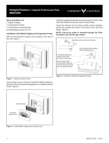
The 52 Bay was designed to allow the owner to
monitor the catalyst temperatures. A small port is
located on the top of the stove, inside the unit. From
that port, wires may be led out of the unit to a
temperature monitoring device. Some Gemini models
have this wiring already done. The port is positioned
to allow for temperatures to be taken approximately 1”
behind the right catalyst. The thermocouple and
monitor should be compatible and should read
temperatures to approximately 1800 degrees F.
Front Mounted Catalytic Probe
Locate screw above the door and to the left of the
damper. Remove the screw and insert catalytic probe.
13

14
3. CATALYST TROUBLESHOOTING
The operation of any wood stove can create problems.
While the use of a catalyst equipped wood stove will
substantially lessen some of these problems, such as
creosote formation, other traditional wood stove
problems may remain. These problems are invariable
related to such conditions as draft, aging or failure of
stove components, flue installation, wood supply and
others.
Here are a few clues that may be of some assistance in
discerning problems:
A sluggish stove performance may be attributed to: a
poor chimney draft; an obstruction in the chimney; the
chimney damper being closed; closing the bypass
damper too soon; burning wet or unseasoned wood; the
combustor being plugged or obstructed, or a
combination of the above.
A drop in overall fuel efficiency may be attributed to:
having cold, windy weather; burning wet, pithy or
spongy wood; the combustor not in operational mode
(200-300 plus degrees); or the combustor being broken
or dislodged.
A high fuel consumption may be attributed to: burning
the wrong type of wood for the desired heat output;
improper regulation of draft or inlet air (close damper
after proper light off, install barometric damper set to
.06 inches of water, or close inlet air as much as
possible); cold, windy weather; or the combustor not
engaged or functioning properly.
Backpuffing may be attibuted to: gusts of wind; a hot
combustor (above 1400 degrees F); or opening doors in
a tightly constructed house.
Smoke rollout when the door is opened may be
attributed to: the manual flue being closed; wind gusts
blowing down the chimney; the combustor not at
operational temperature, or the stove door being opened
too quickly.
Glowing stove parts may be attributed to: running the
stove too hot (excessive amounts of wood); a high draft
(reduce when temperatures become too excessive); a
glowing combustor (this is normal during first 1/3 of
burn cycle), or a chimney fire (close inlet air and outlet
dampers completely - if this does not help, vacate home
and call the fire department immediately).
Creosote accumulation may be caused by one or more of
the following: a poorly insulated chimney; a non-
functioning combustor; types and amounts of wood
burned, or a leaking damper plate.
Creosote leakage from metal flue joints may be caused
by one or more of the following: no chimney cap; metal
flue assembled improperly, or a normal increase in the
moisture due to a higher efficiency of catalytic burning
(condensation on cool chimney walls).
A heavy concentration of smoke leaving the chimney
may be attributed to one or more of the following:
improper wood being burned; the damper being open,
or water vapor (on cold, still days, water vapor is often
mistaken for smoke. Water vapor appears to be white
and tends to rise vertically and dissipate rapidly while
smoke is usually bluish brown and drifts down and
settles in low areas before dissipating).
A poor draft may be attributed to these factors: an
improper chimney height; wrong size flue being used;
cooler temperatures caused by external chimney, or a
massive stone or masonry chimney.
An unhealthy combustor can be attributed to plugging,
catalyst peeling, catalyst deactivation, masking, substrate
cracking (thermal and mechanical), substrate crumbling,
color variations (does not affect performance), or
catalyst abrasion. An excellent guide to pinpointing and
correcting these problems can be found by consulting
the catalyst warranty.

15
4. CATALYST REPLACEMENT
To replace damaged or non-functioning catalytics follow these steps:
A) Loosen the damper tab bolts with 9/16” socket to allow the damper tab to slide back. Lower the cast housing as
shown.
B) Remove the mixing plate, sealing plate and catalyst. Clean the area where the catalyst sits to remove old gasketing.
Inside the stove, check the area where the damper system was located and clean away old gasketing, if necessary.
C) Install the new catalysts. Uncanned catalysts (catalysts not in metal housing) should be wrapped with 1/16”
gasketing before installing. Locate the catalysts ½” from the front of the damper housing. Re-install the sealing.
D) New gasketing should be installed to allow for a seal between the damper housing and the firebox top. This may
be done by putting a layer of gasketing around the top where the housing is located. In both cases, the use of an
adhesive to hold the gasketing in place will make the installation easier.
E) Remount the cast housing in the back of the stove. Tighten damper tab bolts. Make sure the damper slides easily.
Use furnace cement to seal gaps between the sealing plate and the catalysts, the rod guide and the top of the firebox.

Proper operation of your 52 Bay stove will help to
ensure safe, efficient heating. Review these operating
instructions.
1. FUEL SELECTION
The 52 Bay is designed to burn natural wood only.
Higher efficiencies and lower emissions generally result
when burning air dried seasoned hardwoods, as
compared to softwoods or to green or freshly cut
hardwoods. DO NOT BURN THE FOLLOWING:
treated wood, coal, garbage, solvents, colored papers, or
trash. Burning these may result in the release of toxic
fumes and may poison or render the catalytic ineffective.
Burning coal, cardboard, or loose paper can produce
soot, or large flakes of char or fly ash that can coat the
combustor, causing smoke spillage into the room,
rendering the combustor ineffective.
2. BUILDING AND MAINTAINING A FIRE
(A) Open the damper fully by pulling the damper
control panel all the way out.
(B) Place a base of crumpled uncolored newspaper in the
bottom of the stove. Lay pieces of kindling on top of the
newspaper and light it.
(C) As the kindling begins to burn, add several larger
pieces of wood until the fire is burning well. At this
point, regular size logs may be added.
NOTE: Until the fire is burning well, leave the draft
controls in the door fully open.
NEVER USE GASOLINE, GASOLINE TYPE
LANTERN FUEL, KEROSENE, CHARCOAL,
LIGHTER FLUID, OR SIMILAR LIQUIDS TO START
OR “FRESHEN UP” A FIRE IN THIS HEATER. KEEP
ALL SUCH LIQUIDS FAR AWAY FROM THIS
HEATER WHILE IN USE.
(D) For a stove equipped with a catalytic combustor, the
damper must be fully closed after the fire is burning well.
(E) Regulate the heat output of the stove by adjusting
the draft controls to allow a larger fire and vice versa. A
short period of experimentation with the control
settings will allow you to regulate the heat output to
keep your home comfortable.
CAUTION: DO NOT UNPLUG YOUR BLOWER
WHILE THE STOVE IS IN OPERATION.
CAUTION: THE ASH PAN DRAWER MUST BE
CLOSED WHEN THE STOVE IS IN OPERATION.
VIII. OPERATION
3. REFUELING THE STOVE
(A) Before attempting to add fuel to the stove, OPEN
the damper control fully by pulling it all the way out.
This allows the chimney to carry away the additional
smoke that occurs when the door is open.
(B) DO NOT OVERLOAD THE STOVE. Normally,
three or four logs will provide heat for several hours.
Never operate this stove where portions glow red hot.
4. ACHIEVING CATALYST LIGHT OFF FROM A
COLD START
The temperature in the stove and the gasses entering
the combustor must be raised to between 500 and 700
degrees F. for catalytic activity to be initiated. During
the startup of a cold stove, a medium to high firing
rate must be maintained for about 20 minutes. This
assures that the stove, catalyst, and fuel are all
stabilized at the proper operating temperatures. Even
though it is possible to have gas temperatures reach
600 degrees F. within two to three minutes after the
fire is started, if the fire is allowed to die down
immediately, it may go out, or the combustor may stop
working. Once the combustor starts working, heat
generated by burning smoke will keep it working.
5. ACHIEVING CATALYST LIGHT OFF WHEN
REFUELING
During the refueling and rekindling of a “charcoal
phase” fire, operate the stove at a medium or high
firing rate for about 10 minutes to ensure that the
catalyst reaches approximately 600 degrees F.
It is important to periodically monitor the operation
of the catalytic combustor to ensure that it is
functioning properly and to determine when it needs
to be replaced. A non-functioning combustor will
result in a loss of heating efficiency and an increase in
creosote emissions.
16

IX. MAINTENANCE
17
There are areas of the stove and chimney system that
need periodic maintenance to ensure safe and efficient
operation.
1. ASH REMOVAL
When ashes get 3” to 4” deep in your firebox, wait until
the stove has cooled, then remove the grate at the
bottom of the heater into the ash pan below. Carefully
remove the pan. Ashes should be placed on a non-
combustible floor or on the ground, away from all
combustible materials pending final disposal. The ashes
should be retained in the closed container until all
cinders have thoroughly cooled.
NOTE: For the most efficient stove operation leave a
minimum of 2” ash in the firebox at all times. This will
help maintain a hot charcoal bed.
NOTE: DO NOT OVERFIRE THIS HEATER.
Attempts to achieve heat output rates that exceed heater
design specifications can result in permanent damage to
the heater and to the catalytic combustor.
2. CARE OF THE GLASS
The glass supplied with your stove is designed to
withstand extremely high temperatures. However, like
any glass product, IT CAN BE BROKEN! Take care not
to bump it with a log or a poker, and be sure the wood
is entirely inside the stove before attempting to close the
door.
Periodically opening the drafts and allowing the fire to
burn brightly will help reduce the soot buildup on the
glass. The glass may be cleaned with a NON-ABRASIVE
cleaner such as a spray glass cleaner or oven cleaner.
An effective way of cleaning the glass is to dip a
dampened rag in the ashes and scrub the surface clean.
The application of a non-stick cooking spray to the inner
surface of the glass will help keep it clean.
3. CHIMNEY CARE
When wood is burned slowly, it produces tar and other
organic vapors, which combine with expelled moisture
to form creosote. The creosote vapors condense in the
relatively cool chimney flue of a slow burning fire. As a
result, creosote residue accumulates on the flue lining.
The chimney connector and chimney should be
inspected at least twice yearly during the heating season
to determine if a creosote buildup has occurred.
If creosote has accumulated, it should be removed to
reduce the risk of a chimney fire.
NOTE: Insert model stoves should be removed from the
fireplace for cleaning. Slide the stove out and place it on
a piece of cardboard or drop cloths to protect the floor.
The fireplace and throat of the chimney CANNOT be
properly cleaned with the stove in place.
4. STOVE FINISH
All stoves are finished with a specially formulated high
temperature paint. During the first few firings of the
stove, a slight odor of paint may be noticed. This is
normal during the curing process and the fumes are not
hazardous. If they cause irritation, crack a window or
door for a few minutes to disperse the fumes.
NOTE: Although non-toxic, the fumes MAY set off a
smoke detector located near the stove.
5. BLOWER CARE
Remove and clean the blower every four months.
Unplug the blower before removing or servicing.
TO OIL THE BLOWER:
The blower should be oiled at least two times per season
with SAE-20. The oil ports (2) are located on the
opposite ends of the center hub on the top side of the
blower (see illustration).
6. DOOR GASKET REPLACEMENT
Remove all old gasket and clean the gasket channel, if
necessary. Put high temperature silicone adhesive in the
channel and lay the gasket in so that the ends of the
gasket meet in the bottom right corner of the door back.
Press down slightly.
7. MOTOR MAINTENANCE
Use turbine oil when lubricating motor. Perform this
task every six months.

1. If you plan to use an existing chimney with your stove,
inspect it thoroughly to be sure it is sound and clean.
Advise your insurance company to be sure your policy
covers the use of a wood stove.
2. Be sure that firewood, furniture or other combustible
materials are stored a safe distance from the stove.
3. Use smoke detectors near the stove as well as other
areas of the home.
4. NEVER USE FLAMMABLE LIQUIDS TO START
OR “FRESHEN UP” THE FIRE.
5. Periodically inspect the chimney for deterioration and
creosote buildup. Clean it regularly to reduce the
chances of a chimney fire.
6. Keep a fire extinguisher rated for “Class A” fires near
the stove. The dry chemical type is recommended, as
liquid types can cause problems if sprayed onto a hot
stove. BE SURE EVERY MEMBER OF THE FAMILY
KNOWS WHERE THE EXTINGUISHER IS AND
HOW TO USE IT!
7. Use of a chimney cap with an approved spark arrestor
is recommended.
8. Use caution when loading or working around the
stove to prevent burns.
9. Make sure the ash pan drawer is closed when the
stove is in operation.
WARNING: THE INSTALLATION OF THIS STOVE
MUST COMPLY WITH STATE AND LOCAL
REQUIREMENTS AND BE INSPECTED BY THE
STATE OR LOCAL INSPECTOR, IF REQUIRED.
X. SAFETY XI. WARRANTY
18
The Appalachian Stove is warrantied to be free of defects in
materials and workmanship for a period of five years from
the date of purchase when used in accordance with the
recommendations of the manufacturer, with the following
exceptions: electrical, limited to the warranties offered by
those respective manufacturers (1 yr.); glass, refractory,
firebrick, andirons and decorative trim have no warranty.
Defective parts will be repaired or replaced at the
manufacturer’s option. Parts which are returned to
Appalachian Stove and Fabricators, Inc. within 30 days of
purchase and found to be defective on inspection will be
replaced without charge for the new part. After 30 days, parts
covered by the warranty will be repaired or replaced free with
the exception of freight charges which become the
responsibility of the purchaser. All replacement parts are
shipped F.O.B. factory (freight collect). This warranty does
not cover damage caused by alteration, repairs, abuse,
tampering, or improper operation of this unit. It does not
cover damage from handling or acts of God.
This warranty is in lieu of all other warranties expressed,
implied or statutory, and the manufacturer expressly excludes
any implied warranty of fitness for a particular purpose or an
implied warranty of merchantability, and all other obligations
or liabilities of the manufacturer who neither assumes nor
authorizes any person to assume for it any other obligations
or liability in connection with its products. In addition, the
manufacturer shall be held free and harmless from liability
from damage to property or injury to persons related to the
operation, proper or improper use of the equipment. This
warranty applies only to the original purchaser. THERE ARE
NO WARRANTIES THAT EXTEND BEYOND THE
DESCRIPTION ON THE FACE HEREOF.
All claims made by the purchaser under this warranty should
be directed through the dealer from whom the unit was
purchased. If the dealer cannot be contacted after reasonable
effort, claims may be placed with the Appalachian Stove and
Fabricators, Inc.
Stove Model: _________________________________
Serial #: ________________________________
APPALACHIAN STOVE & FABRICATORS, INC.
329 EMMA ROAD
ASHEVILLE, NC 28806
Phone: (828) 253-0164 Fax: (828) 254-7803


/