Page is loading ...

“Ce manuel est disponible en Français sur demande”


3
P68 Pellet Stove
*This appliance is also approved for installation into a shop.
Serial #:
PROTECTION DE SOL
FLOOR PROTECTION
Agence Américaine pour la Protection de l'Environnement
Ce modéle est dispensé par EPA certification d'aprés 40 CFR 60.531
par dèfinition [Appareil á bois (A) << Ratio air/combustible>>]
US ENVIRONMENTAL PROTECTION AGENCY
This model is exempt from EPA certification under 40 CFR 60.531
by definition [Wood Heater (A) "Air-to-Fuel Ratio"]
Harman P68 Pellet Stove
Label measures: 4-3/8" high X 10-3/4"wide
"PREVENT HOUSE FIRES"
Install and Use Only in Accordance With Manufacturer's Installation and Operation
Instructions. Contact Local Building or Fire Officials About Restrictions and
Inspection Requirements in Your Area.
WARNING : THE STRUCTURAL INTEGRITY OF THE MANUFACTURED HOME
FLOOR, WALL, AND CEILING/ROOF MUST BE MAINTAINED.
DO NOT INSTALL IN SLEEPING ROOM. An outside combustion air inlet must be
provided. Refer to Manufacturer’s instructions and local codes regarding the
requirements for passing the exhaust venting system through a combustible wall
or cieling.
Inspect and Clean Exhaust Venting System Frequently.
Use a 3" or 4" diameter type "L" or "PL" venting system.
Do Not Connect This Unit to a Chimney Flue Serving Another Appliance.
FOR USE WITH WOOD PELLET FUEL OR UP TO 50% CORN / PELLET MIXTURE ONLY.
The Use of Other Fuels May Create an Unsafe Condition.
Input Rating Max: 8 lb. fuel/hr.
U.S. Electrical Rating: 115 VAC, 60 Hz, Start 4.1 AMPS, Run 1.1 AMPS
European Electrical Rating: 240 VAC, 60 Hz, Start 2.0 AMPS, Run 1.1 AMPS
Route Power Cord Away From Unit.
DANGER: Risk of Electrical Shock. Disconnect Power Before Servicing Unit.
For Further Instruction, Refer To Owner's Manual.
Replace glass only with 5mm ceramic available from your dealer.
Keep Viewing and Ash Removal Doors Tightly Closed During Operation.
MODEL / Modéle: "P68"
Room Heater Pellet Fuel Burning Type. Also for use in Mobile Homes.
Report #/ Raport # 135-S-13b-2
Tested to / Testé à:
ASTM E1509-04, ULC-S627-00,
and ULC-C1482-M1990
WITHOUT
SIDE SHIELDS WITH
SIDE SHIELDS
Ser# -
DO NOT REMOVE THIS LABEL / NE PAS ENLEVER CETTE ÉTIQUETTE
Appareil de chauffage à granulés de bois Utilisable dans des mobile homes.
P.N. 3-90-06806
"PREVENTION DES INCENDIES"
Respecter scrupuleusement les instructions du constructeur pour l'installation et les
consignes de fonctionnement. Respecter les règles de sécuritè en vigueur dans votre
région.
AVERTISSEMENT POUR MOBILE HOMES: Ne pas installer dans une chambre. ll est
imperatif de prévoir une prise d'alr extérieur. L'intégrité structurale du plancher, du plafond
et des murs doit étre strictement préservée.
Se reporter aux instructions du fabricant et aux réglementations spécifiques locales
concernant les précautions requises lors de la traversée d'un mur ou d'un plafond.
Contróler et nettoyer fréquemment tout le systeme d'evacuation des fumées conformé-
ment aux recommandations du constructeur. Utiliser des tuyaux <<Spécial granulés>>
de Ø76 mm ou 102 mm. Ne pas raccorder ce poéle à un conduit de cheminée déjà
utilisé pour un autre appareil.
FONCTIONNE EXCLUSIVEMENT AVEC DES GRANULES DE BOIS.
ASTM E1509-ULC-C1482-M1990
Appareil de chauffage à granulé type (UM) 84-HUD. Consommation maximum: 3.63 kg/h.
U.S. Electrical Rating: 115 VAC, 60 Hz, Start 4.1 AMPS, Run 1.1 AMPS
Caractéristiques électriques: 240 VAC, 60 Hz-Intensité au démarrage 2.0A -Intensité
fonctionnement normal 1.1A. Tenir le cordon d'alimentation à l'écart du poèle.
DANGER: Risque d'électrocution. Débrancher l'appareil avant toute intervention.
Ne remplacer la vitre qu'avec une vitre céramique 5mm de méme qualité disponible
auprès de votre revendeur.
Pour une information plus compléte, se reporter à la notice d'utilisation. Tenir la porte
hermétiquement close durant fonctionnement.
2"-51mm
WITHOUT SIDE SHIELDS
20"-
508mm
Sans Écrans Latéraux
Date of Manufacture / Date de fabrication:
2010 2011 2012 JAN FEB MAR APR MAY JUN JUL AUG SEP OCT NOV DEC
Fabriqué par: Harman Home Heating 352 Mountain House Road, Halifax PA 17032
Portland
Oregon USA
Tested and
Listed By
OMNI-Test Laboratories, Inc.
A
B
A
WITHOUT SIDE SHIELDS
13"
13"
3"min
3"min
330mm
330mm
76mm min
76mm min
Sans Écrans Latéraux
C
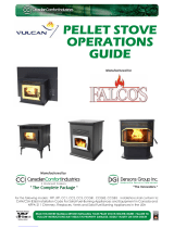
FLOOR PROTECTION / Protection Du Plancher
Sides* (A) 6” / Côtés (A) 152mm
Back (B) 0” / Arrière (B) 0mm
Front* (C) 6” / Avant (C) 152mm
*Measured from Glass Opening
*Mesurer à partir de la surface de la porte en verre
Floor Protection Must Be a Non-Combustible Material.
Must Also be Placed Under Any Horizontal Flue
Connector, Extending 2” or 51mm Beyond the Pipe
Measurement. Pour protéger le plancher, il faut sous
le poêle un matériau. Qui doit aussi être placé sous
les parties horizontales du tuyau de raccord à la
cheminée et s’étendre à 51mm o 2 po. au-delà de la
mesure du tuyau.
Made in U.S.A. of US and imported parts. / Fabriqué
aux États-Unis-d’Amérique par des pièces d’origine
américaine et pièces importées.
Back Wall / Entre Mur Arrière 2”/ 51mm 2“/ 51mm
Side Wall / Entre Paroi Latérale 20”/ 508mm 14“/ 355mm
CORNER INSTALLATION / EN ANGLE
Walls to Appliance 14”/355mm 20“/508mm
Entre Murs et appareil
Flue Connector/Raccord à la cheminée 3” /76mm
MINIMUM CLEARANCES TO COMBUSTIBLES/
DISTANCES DE SECURITE PAR RAPPORT AUX
MATERIAUX COMBUSTIBLES:
Sans Écrans
Latéraux Avec Écrans
Latéraux
This label is located on the back of the unit.
Please copy the Serial Number for future reference.

4P68 Pellet Stove
Please read this entire manual before installation
and use of this pellet fuel-burning room heater.
Failure to follow these instructions could result in
property damage, bodily injury, or even death.
Important Notes / Safety Concerns 5
Installation 6
Venting 8
Automatic Operation 15
Manual Operation 18
ESP Control 20
Low Draft Voltage Adjustment 21
Room Sensor 22
Maintenance 23
Troubleshooting 28
Specications 29
Options 30
Wiring Diagram 32
Power Failure / Back-up 34
Warranty 35
Service Parts Listing 37
The Award-Winning P68 Pellet Stove has the widest BTU range available, giving you 0 to 68,000 BTU
when you need it, automatically. The only thing you need to do is set your desired room temperature
and ll the hopper. With the P68 you will notice even heat throughout your home and a level of
convenience you never thought possible.
The P68 epitomizes the capability of Harman Pellet Stoves, taking advantage of Harman’s 20
years of pellet stove design, technology and manufacturing. This 68,000 BTU stove has the highest
output, smartest controls, widest heating range, and minimal maintenance. The P68’s huge output
is managed by a microprocessor that senses the room temperature and the re temperature with
tiny thermister probes and then determines the best feed rate. This improved and smarter control
also has a diagnostic port for connecting an external display showing live working data for easier
troubleshooting.
The platinum combination is Harman’s Patented Feeder & Burn Pot, and ESP Control which have
been developed to their highest state. These features work together to allow amazing heat output with
different fuel quality, ash content and moisture.
When installing a solid fuel
appliance, it is also recommended to install Smoke
and Carbon Monoxide Detectors on every level of
the house. During the initial ring of the appliance,
some smoke or odor may occur due to paint
curing. You may want to keep some windows open
for ventilation during the rst few hours of burning
to prevent smoke detector activation. Test your
smoke and carbon monoxide detectors regularly.
352 Mountain House Road
Halifax, PA 17032

5
P68 Pellet Stove
The P68 is approved for use with wood pellets and
for a mixture of shelled corn and wood pellets. See the
corn mixture addendum on page 33 of this manual.
Store fuel in a dry area, well away from the appliance.
Remember, corn is a food source and will attract bugs
and other pests. If using corn for burning, keep it in a
sealed container outside your home.

6P68 Pellet Stove
The P68 is bolted (1/4 x 1" hex head bolts) to the skid
to prevent movement during shipping.
To free the stove from the skid you must remove the
hold-down bolts in the rear of the pedestal base.
The rear cover panels need removed from the stove to
make it easier to get at the hold-down bolts.
The rear cover panels must be reinstalled once the
installation is complete. These panels are to gaurd from
contact with hot and moving parts. To reduce the risk
of electric shock, disconnect power before removing
the rear covers.
Install the rebrick vertically on the angle bracket above
the burnpot.
Install the cast iron ame guide on top of the burn pot.
Make sure that the ame guide is fully seated on the
vertical sides of the burn pot and that the back of the
guide rests against the body of the stove.
Most pellet vent requires a minimum of 3" of clearance
to combustible materials.
Spring Washer
1. Remove wood handle, spring washer, and socket head cap screw ¼-20 x 2-1/4" from hardware pack.
2. Install spring washer and wood handle onto socket head cap screw as shown in g. 2 and thread onto latch
on front door.
3. Tighten using a 3/16" hex key wrench.
Wood Handle
1/4-20 x 2-1/4
socket- head screw
Fig. 2
Rear Cover
Panels
Shipping Bolts
Note: These same holes
are used for securing the
stove in mobile home
installation.
Fig. 1

7
P68 Pellet Stove
Place the stove on a noncombustible type oor or oor
protector that extends a minimum of 6 inches (152mm) to the
front of the load door opening, 6 inches (152mm) to the sides
of the door opening, and 6 inches to the rear. Floor protection
must also extend 2 inches (51mm) beyond each side of any
horizontal ue pipe. The minimum oor protector material
is 20 gauge sheet metal. Other oor protector materials are
ceramic tile, stone, brick, etc.
Place the stove away from combustible walls at least as far
as shown in Figures 3, 4, and 5. Please note the difference in
side wall clearance with and without side shields.
Note that the clearances shown are minimum for safety but
do not leave much room for access when cleaning or servicing.
Please take this into account when placing the stove.
Connect the power cord to a 120 V.A.C. 60Hz grounded
receptacle. (A surge protector is recommended to protect the
circuit board.) Also be sure that the polarity of the outlet that
the stove is plugged into is correct.
Prior to installing the ue pipe, connect a draft meter. (The
draft meter must have a minimum range of 0 - .5") Record the
rst reading. Connect ue pipe to stove and be sure all doors
and windows in the home are closed. Record the second
draft reading_______. If the second reading is more than .05"
lower than the rst reading, check for possible restrictions or
the need for outside air (see page 10). For more information
on the draft test procedure, refer to Page 21.
When installing this unit in a mobile home, several
requirements must be followed:
1. The unit must be bolted to the oor. This can be done with
1/4" lag screws through the 2 holes in the base plate.
2. The unit must also be connected to outside air. See page 10.
3. Floor protection and clearances must be followed as shown.
4. Unit must be grounded to the metal frame of the mobile
home.
5. Be sure to follow the vent manufacturer's guidelines to
provide for a sufcient vapor barrier where the ue penetrates
the outside.
6. The top section of any chimney or venting must be removable
to a height of 13' (3.9 M) to allow for transport.
7.
The factory-built chimney must conform to CAN/ULC-S629,
Standard for 650°C Factory-Built Chimneys.
Clothing and other ammable materials should not be placed
on or near this unit.
Fig. 3
9"(228mm)-
13"(330mm)
9"(228mm)With Side Shields
13"(330mm) Without Side Shields
9"(228mm)-
13"(330mm)
Fig. 4
2"(51mm)
14"
(355mm)
36"(914mm)
Fig. 5
2"(51mm)
36"(914mm)
20"(508mm)
Fig. 6
6"
152 mm
6" (152mm)
from
pedestal
base
25" minimum
33" minimum
6" (152mm)
from door
opening

8P68 Pellet Stove
WARNING: Venting terminals must not be recessed
into a wall or siding.
NOTE: Only PL vent pipe wall pass-throughs and re
stops should be used when venting through combustible
materials.
NOTE: Always take into consideration the effects
of the prevailing wind direction or other wind currents
that may cause yash and/or smoke when placing the
termination vent.
A. The clearance above grade must be a minimum
of 18".
B. The clearance to a window or door that may be
opened must be a minimum of 48" to the side, 48" below
the window/door, and 12" above the window/door.
( )
C. A 12" clearance to a permanently closed window
is recommended to prevent condensation on the
window.
D. The vertical clearance to a ventilated soft located
above the terminal within a horizontal distance of 2 feet
(60 cm) from the center-line of the terminal must be a
minimum of 18".
E. The clearance to an unventilated soft must be
a minimum of 12".
F. The clearance to an outside corner is 11" from
center of pipe.
G. The clearance to an inside corner is 12".
H. A vent must not be installed within 3 feet (90 cm)
above a gas meter/regulator assembly when measured
from the horizontal center-line of the regulator.
I. The clearance to service regulator vent outlet must
be a minimum of 6 feet.
J. The clearance to a non-mechanical air supply inlet
to the building or the combustion air inlet to any other
appliance must be a minimum of 48”.
K. The clearance to a mechanical air supply inlet must
be a minimum of 10 feet.
()
L. The clearance above a paved sidewalk or a paved
driveway located on public property must be a minimum
of 7 feet.
M. The clearance under a veranda, porch, deck or
balcony must be a minimum of 12 inches.
NOTE: The clearance to vegetation and other exterior
combustibles such as mulch is 36” as measured from
the center of the outlet or cap. This 36” radius continues
to grade or a minimum of 7 feet below the outlet.
Certain Canadian and or Local codes or regulations
may require different clearances.
A vent shall not terminate directly above a side-
walk or paved driveway which is located between two
single family dwellings and serves both dwellings.
Only permitted if veranda, porch, deck, or balcony is
fully open on a minimum of 2 sides beneath the oor.
= Vent terminal

9
P68 Pellet Stove
A combustion blower is used to extract the combustion
gases from the rebox. This causes a negative pressure
in the rebox and a positive pressure in the venting
system as shown in Fig. 7. The longer the vent pipe and
more elbows used in the system, the greater the ow
resistance. Because of these facts we recommend using
as few elbows as possible and 15 feet or less of vent
pipe. The maximum horizontal run should not exceed
48". If more than 15 feet of pipe is needed, the interior
diameter should be increased from 3" to 4" because
a larger pipe causes less ow resistance.
Approved 3" or 4" Pellet Vent Pipe Such As,
Type "PL", Must Be Used.
Fig. 7
Pellet venting pipe (known as PL vent) is constructed
of two layers with air space between the layers.
This air space acts as an insulator and reduces the
outside surface temperature to allow a clearance to
combustibles of 1 to 3 inches. The sections of pipe
lock together to form an air tight seal in most cases.
However, in some cases a perfect seal is not achieved.
For this reason and the fact that the P68 operates with a
positive vent pressure
Aluminum
tape can also be used for any joint that is 1ft. or more
from the outlet of the stove.
T
without exhaust blower
operation. Negative pressure in the house will resist this
natural draft if not accounted for in the pellet appliance
installation.
Heat rises in the house and leaks out at upper levels.
This air must be replaced with cold air from outdoors,
which ows into lower levels of the house. Vents and
chimneys into basements and lower levels of the house
can become the conduit for air supply, and reverse
under these conditions.
= Positive Static Pressure
= Negative Static Pressure

10 P68 Pellet Stove
Outside air ex pipe
goes here.
Inlet Cover part#
1-10-08542
Flex pipe part#
1-00-08543 (25')
Direct Vent Wall Passthrough Kit
(part #1-00-677077)
Per national building codes, consideration must
be given to combustion air supply to all combustion
appliances. Failure to supply adequate combustion air
for all appliance demands, may lead to back-drafting of
those and other appliances.
When the appliance is side-wall vented: The air
intake is best located on the same exterior wall as the
exhaust vent outlet and located lower on the wall than
the exhaust vent outlet.
When the appliance is roof vented: The air intake is
best located on the exterior wall oriented towards the
prevailing wind direction during the heating season.
The outside air connection will supply the demands of
the pellet appliance, but consideration must be given to
the total house demand. House demand may consume
some air needed for the stove, especially during a power
failure. It may be necessary to add additional ventilation
to the space in which the pellet appliance is located.
Consult with your local HVAC professional to determine
the ventilation demands for your house.
To install outside air use 2 3/8" I.D. non-combustible
flex pipe. There is a break-away hole on the rear
panel of the P68 stove which must be removed before
connecting the ex pipe. The pipe should be run outside
and terminate to the side or below the vent pipe outlet
so the ue outlet is more than 12" from the inlet cover.
The maximum length run of this pipe is 15 feet. If a
longer run is needed the size must be increased to 3".
Inlet cover, part number 1-10-08542 should be used to
keep birds, rodents, etc.out of the pipe.
You may choose to use the optional Direct Vent Wall
Passthrough Kit (part #1-00-677077) which incorporates
the venting passthrough and outside air inlet into one
component.
In Canada, ULC-S627 requires that all
outdoor-aired space heaters be secured to the structure.
To reduce probability of reverse drafting during shut-down conditions, Hearth & Home Technologies strongly
recommends:
• Installing the pellet vent with a minimum vertical run of ve feet, preferably terminating above the roof line.
• Installing the outside air intake at least four feet below the vent termination.
To prevent soot damage to exterior walls of the house and to prevent re-entry of soot or ash into the house:
• Maintain specied clearances to windows, doors, and air inlets, including air conditioners.
• Vents should not be placed below ventilated softs. Run the vent above the roof.
• Avoid venting into alcove locations.
• Vents should not terminate under overhangs, decks or onto covered porches.
• Maintain minimum clearance of 12 inches from the vent termination to the exterior wall. If you see deposits
developing on the wall, you may need to extend this distance to accommodate your installation conditions.

11
P68 Pellet Stove
This method also provides excellent venting
for normal operation but requires the stove to be
installed farther from the wall. The vertical portion of
the vent should be three to ve feet high and at least
three inches from a combustible wall. This vertical
section will provide natural draft in the event of a
power failure.
If the stove is installed below grade be sure the
vent termination is at least 18" above grade. The
outlet must also be 1 foot from the house/building.
Note: Do not place joints within wall pass-
throughs.
This method provides excellent venting for normal
operation and allows the stove to be installed closest
to the wall. Two inches from the wall is safe; however,
four inches allows better access to remove the rear
panel. The vertical portion of the vent should be three
to ve feet high. This vertical section will help provide
natural draft in the event of a power failure.
36" min
clearance to any
combustible
material
12" min. wall to outlet
Fig. 8
Fig. 9

12 P68 Pellet Stove
This method provides excellent venting for normal
operation. This method also provides natural draft in
the event of a power failure. If the chimney condition is
questionable* you may want to install a liner as in method
#7.
*The chimney should be inspected and cleaned before
installing your stove. If you discover that the chimney does
not have a clay tile liner or has cracks or aking of the tile
liner you will need to install a stainless steel liner within
the chimney. In most cases the inside diameter of this liner
should be 4". Either exible or rigid liner may be used for
this purpose. Refer to Method 6 & 7.
Be sure to design the venting so that it can be easily
cleaned.
This method provides excellent venting for normal
operation. This method also provides natural draft in
the event of a power failure. If the chimney condition is
questionable* you may want to install a liner as in method
#6.
*The chimney should be inspected and cleaned before
installing your stove. If you discover that the chimney does
not have a clay tile liner or has cracks or aking of the tile
liner you will need to install a stainless steel liner within
the chimney. In most cases the inside diameter of this liner
should be 4". Either exible or rigid liner may be used for
this purpose. Refer to Fig. 6 & 7.
The chimney should be sealed at the damper using a
steel plate. Kaowool, mineral wool or an equivalent non-
combustible insulation is recommended to be installed
on top of the sealing plate to reduce the possibility of
condensation. The connector pipe should extend through
the smoke chamber to the base or into the rst ue tile.
Be sure to design the venting so that it can be easily
cleaned.
Fig. 10
Fig. 11

13
P68 Pellet Stove
This method provides excellent venting for normal
operation. This method also provides natural draft in
the event of a power failure.
In some places in the US and Canada it is required
that the vent pipe extend all the way to the top of the
chimney.
In this method a cap should also be installed on the
chimney to keep out rain. Be sure to use approved
pellet vent pipe ttings. Seal pipe joints with silicone or
aluminum tape in addition to the sealing system used
by the manufacturer. Pipe size should be increased to
4" using this method.
This method provides excellent venting for normal
operation. This method also provides natural draft in
the event of a power failure.
In some places in the US and Canada it is required
that the vent pipe extend all the way to the top of the
chimney. The pipe or liner inside the chimney should
be 4"diameter.
In this method a cap should also be installed on the
chimney to keep out rain.
Fig. 12
Fig. 13

14 P68 Pellet Stove
Through the ceiling vent, follow PL vent
manufacturers recommendations when using wall
and ceiling pass throughs.
It is recommended that
outside air be installed with
this venting conguration to
reduce smoke and creosote
smell in the room in the event
of power failure.
Min. above ground level
18"
Fig. 15
Fig. 14
PL vent manufacturer's
restop spacer and
support
(See Page 7 for
corner installation
clearances)
Storm collar
Flashing
3" min. 3" min.
12" min.
3" min.
3" min.
No insulation or
other combustible
materials are
allowed within 3" of
the pellet vent pipe.
Unless specied
by the pipe
manufacturer
12" min. wall to outlet
36" min clearance to any
combustible material
Fig. 16
Shaded area represents
the minimum clearance to
combustible materials such as
shrubbery, mulch or tall grasses.

15
P68 Pellet Stove
The P68 is a fully automatic stove that features two
operating modes; and
In Stove Temperature Mode, you
select a burn rate and the stove will remain at the same
burn rate regardless of the room temperature.
In the Room Temperature Mode the stove constantly
monitors the temperature in the room and adjusts the size
of the re and the heat output of the stove so that the
room is kept at a constant temperature. Room mode, in
the AUTO position, has the added advantage of turning
the stove off if no heat is required and turning the stove
on again when the room temperature drops below your
desired room temperature.
Most consumers use the stove in the Room Temperature
Mode because it is the easiest and most efcient method
of keeping the room at a given temperature. In the Room
Temperature Mode, the Room Sensing Probe constantly
monitors room temperature. As the weather changes
outside and your home needs varying amounts of heat to
be at a desired temperature, the stove will automatically
increase size and heat output of the re so that a constant
even temperature is maintained. If the weather warms up
and no heat is required the stove will gradually shut down.
When the house cools down the stove will automatically
bring the room temperature to the precise temperature
you desire.
In the Room Temperature Mode you can select either
for theusing the igniter
toggle switch. When the toggle switch is in the Auto
position the igniter located inside the burn pot is ready
to automatically light the re when required. When the
toggle switch set to the Manual position the stove can
be lit manually with either a gel or a wax type re starter.
(see lighting instructions on page 18.) With the igniter
toggle switch set in the Manual position the stove will
automatically adjust heat output, but the stove will not
automatically shut down if no heat is required. Instead it
will go to its lowest setting and remain there. The Manual
position on the igniter toggle switch lets you light the stove
manually, should the igniter fail for any reason. Secondly
if you are using the Harman battery back up system the
Manual setting will prevent the stove from turning off and
on during a power failure, which would drain the back
up battery, and possibly cause damage to the back-up
or the stove.
In the Room Temperature Mode, the distribution blower
speed can be increased or decreased by adjusting the
Room Temp/Off/Stove Temp dial between L and H. As
output of the stove increases, the speed of the blower
will increase automatically to insure that more heat is
transferred out into the room. The distribution blower will
shut off as the room reaches the set temperature, this
will prevent overheating of the room.
This setting, see above,
will produce a room temperature of 70 degrees with the
distribution blower at medium speed.

16 P68 Pellet Stove
The setting above will produce continuous maximum heat output
with the distribution blower at full speed.
The setting above will produce continuous medium heat output
with the distribution blower at low speed.
The best way to shut down the stove is simply
let it run out of pellets. The stove will shut down
automatically. Alternatively, you can turn the Mode
Selector to “off”. This will cause the re to gradually
die down and go out. The re will not go out
immediately and may take more than an hour to fully
shut down.
If the stove is left to run out of fuel, you may get a
6 blink status light. If this happens simply reset the
control board by turning the mode selector to OFF
and back ON.
In the Stove Temperature Mode and with the igniter
toggle switch in the Auto position, the stove will light
automatically and can be adjusted to the desired setting
using the same temperature control dial as is used in
the Room Temperature Mode. The heat output and fuel
consumption will remain constant regardless of room
temperature. The settings from 1 to 7 on the inner ring
of the dial provide for relative heat output settings with
1 being low and 7 being the maximum.
In Stove Temperature Mode, the stove will not
automatically shut off unless the stove runs out of fuel
or is turned off.
pull the plug to shut down the stove. This will
stop the combustion blower and smoke will escape
through window and door gaskets.
When the igniter toggle switch is set to manual in
this mode, the distribution blower will not turn on with
a temperature dial setting from 1 to 5. The advantage
of this mode is to allow the operator to have a large
viewing re without blowing extra heat into the room.
During manual operation, with the temperature dial set
at #4 or less, the distribution fan will not operate. A #4
on the temperature dial and a #5 on the feed adjuster is
approximately 80% output. It is not necessary to operate
the distribution blower below this point. Therefore, the
control allows a higher burn rate ( a larger viewing re)
without an excess of hot air blowing into the room.
An example of when to use the Manual Stove
Temperature Mode is if you want to watch a large re
and the room is already up to temperature. The Stove
Temperature Mode allows you to have a larger re and
a lower sound level, without the distribution blower.
For most premium grade pellet fuels the Feed
Adjuster Knob should be set at 4. If higher ash fuels
are used the setting should be increased to 5 or 6. Also
higher settings are required if you would like to get the
maximum heat output from the stove. At the maximum
burn rate (with the temperature dial on 7/90° and the
feed adjuster at 6) there should be 1" or more of ash
on the front of the burn pot. If there is less than 1" of
ash, turn the feed adjuster knob down to a lower setting.

17
P68 Pellet Stove
1. Fines are small pieces of broken pellets (sawdust). Fines do not
ow easily and often build up on the hopper funnel bottom angles.
You can push these nes into the feeder opening and then ll the
hopper with pellets. As the system works, they will be burned. Or
you can clean them out before lling the hopper.
2. The "TEST" cycle will operate the feeder motor for exactly one
minute. Turning to "TEST" again and again may purge too much
fuel into the burn pot causing excessive smoke on start-up.
3. The rebox low pressure switch and the hopper lid position switch
will not allow the auger motor or the igniter element to operate if the
hopper, view door or the ash pan door are open.
4. Adjust Feed Rate. If this is your rst re or you are trying different
pellets, set the feed adjuster to #4, Fig. 17. This is a conservative
number and will probably need to be increased. After you know a
feed rate setting that works well, use that setting. Remember, if your
feed rate is too high you may waste fuel.
5. This is usually a weekly maintenance procedure. Cleaning the
burn pot with the scraper with a small amount of new fuel in the
bottom is not a problem. First, scrape the ashes on the front of the
burn pot into the ash pan. Then, scrape the top surface of the burn
pot downward into the base of the burn pot. When the stove is
ignited these scrapings will be pushed out by the feeder and burned.
6. The ash pan can hold the ashes from approximately 1 ton of
premium fuel. This means the ashes will only need to be emptied
a few times a year.
7. Setting the feed adjuster # for maximum burn: With the unit
burning in "AUTO", turn to "Stove Mode" and put the fan on "H".
Set the Temperature Dial to #7. Allow the unit to burn for about 30
minutes and check ash on front of burn pot. Fig. 18. If the ash line
is larger than 1", turn the feed adjuster from #4 to #5. Allow another
30 minutes of burn time and check again. If , at #6 setting, a 1" or
less ash bed is not obtainable, it is not a problem. The 1" ash bed
is only at maximum burn rate and at most normal settings the ash
bed will be larger.
Fig. 17 SeeHint #7.
Fig. 18
1"
Flame Guide
Make sure the unit is plugged into a 120 VAC,
60 HZ electrical source. The power light should be the
only light lit.
1.
2. with pellets.1
3. with scraper, if necessary.5
4.
(for one 60 second cycle).2 This
will feed pellets into the auger tube and also allow you
to check the motors for operation.
5.
6. into the "AUTO" position.
7. to desired room
temperature.
8. to Room Temperature or Stove
Temperature.
9. with pellets and as
required.6
HOT WHILE IN OPERATION. KEEP CHILDREN,
CLOTHING AND FURNITURE AWAY.
CONTACT MAY CAUSE SKIN BURNS.
KEEP HOPPER LID, FIRE DOOR, AND
ASH DRAWER PROPERLY CLOSED WHEN
APPLIANCE IS IN OPERATION.

18 P68 Pellet Stove
The P68 Pellet Stove is capable of manual operation. This also allows the operator
to manually control operation during an emergency (i.e. igniter failure, or when using
certain generators or other auxilliary power source.)
The unit can be switched between "AUTO" and "MANUAL" at any time during
operation.
The re will have to be lit with starting gel and a match,
or started automatically, see "Automatic Operation" on
Page 15. Turn to "Manual" position after the ignition
cycle begins.
The difference between "AUTO" Room Temperature
Mode and "Manual" Room Temperature Mode is that
the re will not go out as the room temperature goes
above the control board setting. The unit can only go to
low burn and will remain there until it runs out of fuel or
until more heat is needed and the feed rate increases.
Feed rate adjustments and dial settings are the same
as "AUTO" settings. The blower will shut off completely
if the temperature on the ESP is too low.
The advantage of this mode is to allow the operator
to have a large viewing re without blowing extra heat
into the room.
During operation, with the temperature dial set at #4
or less, the distribution fan will not operate. A #4 on
the temperature dial and a #5 on the feed adjuster is
approximately 80% output. It is not necessary to operate
the distribution blower below this point. This control
setting allows a higher burn rate (a larger viewing re)
without an excess of hot air blowing into the room.
An example of when to use the Manual Stove
Temperature Mode is if you want to watch a large re
and the room is already up to temperature. The Stove
Temperature Mode allows you to have a larger re and
a lower sound level, without the distribution blower.
Room Temperature Mode: This
setting, see below, will produce a
room temperature of 70 degrees
with the distribution blower at
medium speed.
This setting will produce a large viewing re
without a distribution blower operating.

19
P68 Pellet Stove
1. Fines are small pieces of broken pellets (sawdust). Fines do not
ow easily and often build up on the hopper funnel bottom angles.
You can push these nes into the feeder opening and then ll the
hopper with pellets. As the system works, they will be burned. Or
you can clean them out before lling the hopper.As the system
works, they will be burned.
2. The "TEST" cycle will operate the feeder motor for exactly one
minute. Turning to "TEST" again and again may purge too much
fuel into the burn pot causing excessive smoke on start-up.
3. The rebox low pressure switch and the hopper lid position switch
will not allow the auger motor or the igniter element to operate if the
hopper, view door or the ash pan door are open.
4. Adjust Feed Rate. If this is your rst re or you are trying different
pellets, set the feed adjuster to #4, Fig. 19. This is a conservative
number and will probably need to be increased. After you know a
feed rate setting that works well, use that setting. Remember, if your
feed rate is too high you may waste fuel.
5. This is usually a weekly maintenance procedure. Cleaning the
burn pot with the scraper with a small amount of new fuel in the
bottom is not a problem. First, scrape the ashes on the front of the
burn pot into the ash pan. Then, scrape the top surface of the burn
pot downward into the base of the burn pot. When the stove is
ignited these scrapings will be pushed out by the feeder and burned.
6. The ash pan can hold the ashes from approximately 1 ton of
premium fuel. This means the ashes will only need to be emptied
a few times a year.
7. Setting the feed adjuster # for maximum burn: With the unit
burning in "AUTO", turn to "Stove Mode" and put the fan on "H".
Set the Temperature Dial to #7. Allow the unit to burn for about 30
minutes and check ash on front of burn pot. Fig. 21. If the ash line
is larger than 1", turn the feed adjuster from #3 to #4. Allow another
30 minutes of burn time and check again. If , at #6 setting, a 1" or
less ash bed is not obtainable, it is not a problem. The 1" ash bed
is only at maximum burn rate and at most normal settings the ash
bed will be larger.
Fig. 20
Fig. 19
Fig. 21
1"
See Hint #7.
Make sure the unit is plugged into a 120 VAC, 60 HZ
electrical source.
To avoid unwanted smoke, Be sure there
is no fuel or other combustibles in the ash pan prior to
lighting.
Keep all doors closed during operation. Maintain all
seals and gaskets in good condition.
Use only the burn pot, as supplied in the rebox, to
support or contain the burning fuel. No other form of
grate or rack is permitted.
.
No. 4 is good for most pellets.4
This will reset the control and
start the combustion motor.
(Do Not Over Fill).
Stir the gel
into pellets for faster lighting.
The use of a starting gel that
is commercially marketed for use with pellet stoves
is permitted when performing a cold start. Also
be sure to perform the above steps in sequence to
ensure combustion blower operation before applying
the starting gel. Follow the starter manufacturer's
instructions for proper application.
Operation will begin when the re reaches the
proper temperature.3

20 P68 Pellet Stove
Feed adjuster
Sets the maximum feed
rate
Test
Runs all motors at full
speed for one minute
to check operation.
Afterwards, it will simulate
a minimum burn and the
combustion blower will
remain on low.
Distribution Blower
speed adjustment
range.
L = low
H = high
Variable speed anywhere
between L and H; although
as the stove temp. goes up,
so does the low end of the
scale.
Temp dial
Allows you to adjust the room temperature in Room
Temp Mode using the outer scale marked in degrees
Fahrenheit. It also allows you to adjust the stove
temperature while in Stove Temp Mode using the
inner scale marked from 1 to 7.
Mode Selector
Allows you to choose between
Room Temp Mode, Stove Temp
Mode, or OFF. Also allows you
to vary the distribution blower
speed by turning the knob to the
high or low side of each mode.
Power Light
Indicates power to the
control.
Indicates power to the
feed motor.
Indicates power to the
igniter
Indicates power to
combustion blower
Status Light
Will be lit in either stove
or room temp mode
when pointer is not
within off position band
except after normal shut
down. Blinks to indicate
errors listed below.
Indicates power to
distribution blower.
Indicates an incomplete ESP circuit, or that
the ESP (Exhaust Sensing Probe) Has gone out of
range a specic number of times. This may indicate
the need for cleaning the exhaust. Perform a manual
reset*. If the code persists, contact your dealer.
Can occur only in Room Temp Mode and
indicates Room Sensing Probe failed or not installed.
If a Room Sensing Probe is then installed, the status
light will automatically reset.
Indicates that
the unit has failed to light within the 36 minute start
cycle. To reset - Turn Mode Selector to "OFF", then
turn to either mode again.
: Indicates that the control has calculated poor
or incomplete combustion occurring for more than 50
minutes.
A six blink status may be set if the stove is allowed to
run out of pellets. To reset, turn mode selector to "OFF"
then back on to the desired mode. If the unit was not
out of pellets, see Troubleshooting section, Page 28,
for more details.
- disconnect power cord for a few sec-
onds and reconnect. If error still occurs call your Dealer.
Dealer Diagnostic Port
For dealer maintenance
only. Requires special
DDM monitor supplied
to Harman Dealers
exclusively.
Igniter switch
Set to appropriate Start-
Up mode.
/