Page is loading ...


Agence Américaine pour la Protection de l'Environnement
Ce modéle est dispensé par EPA certication d'aprés 40 CFR 60.531 par dènition [Appareil á bois (A) << Ratio air/combustible>>]
US ENVIRONMENTAL PROTECTION AGENCY
This model is exempt from EPA certication under 40 CFR 60.531 by denition [Wood Heater (A) "Air-to-Fuel Ratio"]
Harman P61A Pellet Stove
Label measures: 4-3/8" high X 10-3/4"wide
Black Background with bare metal for print-adhesive backed, metal plate.
"PREVENT HOUSE FIRES"
Install and use only in accordance with manufacturer's installation and operation
instructions. Contact local building or re ofcials about restrictions and inspec-
tion in your area.
WARNING FOR MANUFACTURED HOMES: Do not install appliance in a sleeping
room. An outside combustion air inlet must be provided. The structural integrity of
the manufactured home oor, ceiling and walls must be maintained.
Refer to manufacturer's instructions and local codes for precautions required for
passing chimney through a combustible wall or ceiling. Inspect and clean exhaust
venting system frequently in accordance with manufacturer's instructions.
Use a 3" or 4" diameter type "L" or "PL" venting system.
Do not connect this unit to a chimney ue servicing another appliance.
FUELS: WOOD PELLET FUEL OR UP TO 50% CORN/PELLET MIXTURE ONLY.
Input Rating Max: 5.5 lb. fuel/hr.
U.S. Electrical Rating: 115 VAC, 60 Hz, Start 4.1 AMPS, Run 1.1 AMPS
European Electrical Rating: 240 VAC, 60 Hz, Start 2.0 AMPS, Run 1.1 AMPS
Route power cord away from unit.
DANGER: Risk of electrical shock. Disconnect power supply before servicing.
For further instruction, refer to owner's manual.
Replace glass only with 5mm ceramic available from your dealer.
Keep viewing, fuel loading, and ash removal doors closed during operation.
Report #/ Raport # 135-S-22-4
Tested to / Testé à:
ASTM E1509-04, ULC-S627-00,
and ULC/ORD-C1482-M1990
WITHOUT
SIDE SHIELDS
WITH
SIDE SHIELDS
Ser# - 008
DO NOT REMOVE THIS LABEL / NE PAS ENLEVER CETTE ÉTIQUETTE
MADE IN USA / Fabriqué aux É.-U.
Appareil de chauffage à granulés de bois Utilisable dans des mobile homes. Cet
appareil de chauffage à granulés a été essayé et homologué pour les maisons
préfabriquées, conformément aux normes 814-23-900 à 814-23-909 de l'OAR.
P.N. 3-90-08626
MINIMUM CLEARANCES
TO COMBUSTIBLES:
Back Wall To Appliance 2" 2"
Side Wall To Appliance 18" 12"
Corner Installation
Walls To Appliance 13" 9"
FLOOR PROTECTION-U.S. CANADA
Sides (A) 6" / 15 cm 8" / 20 cm
Back (B) 1" / 2.5 cm 1" / 2.5 cm
Front (C) 6" / 15 cm 18" / 45 cm
Use a non-combustible(Min;2.24k)oor protector extending
under the unit and to the sides, front, and back of unit as
shown in Floor Protection Diagram. Measure front distance
from the surface of the glass door.
Recommended: Non-combustible oor protection extending
beneath any horizontal sections of venting, including the "T"
on the back when venting vertically.
"PREVENTION DES INCENDIES"
Respecter scrupuleusement les instructions du constructeur pour l'installation et les
consignes de fonctionnement. Respecter les règles de sécuritè en vigueur dans votre
région.
AVERTISSEMENT POUR MOBILE HOMES: Ne pas installer dans une chambre. ll est
imperatif de prévoir une prise d'alr extérieur. L'intégrité structurale du plancher, du plafond
et des murs doit étre strictement préservée.
Se reporter aux instructions du fabricant et aux réglementations spéciques locales
concernant les précautions requises lors de la traversée d'un mur ou d'un plafond.
Contróler et nettoyer fréquemment tout le systeme d'evacuation des fumées conformé-
ment aux recommandations du constructeur. Utiliser des tuyaux <<Spécial granulés>>
de Ø76 mm ou 102 mm. Ne pas raccorder ce poéle à un conduit de cheminée déjà
utilisé pour un autre appareil.
FONCTIONNE EXCLUSIVEMENT AVEC DES GRANULES DE BOIS.
ASTM E1509-ULC-C1482-M1990
Appareil de chauffage à granulé type (UM) 84-HUD. Consommation maximum: 2.5 kg/h.
U.S. Electrical Rating: 115 VAC, 60 Hz, Start 4.1 AMPS, Run 1.1 AMPS
Caractéristiques électriques: 240 VAC, 60 Hz-Intensité au démarrage 2.0A -Intensité
fonctionnement normal 1.1A. Tenir le cordon d'alimentation à l'écart du poèle.
DANGER: Risque d'électrocution. Débrancher l'appareil avant toute intervention.
Ne remplacer la vitre qu'avec une vitre céramique 5mm de méme qualité disponible
auprès de votre revendeur.
Pour une information plus compléte, se reporter à la notice d'utilisation. Tenir la porte
hermétiquement close durant fonctionnement.
2"-5cm
WITHOUT SIDE SHIELDS
18"-
45cm
Sans Écrans Latéraux
Tests réalisés par OMNI-TEST LABORATORIES,
Report № 135-S-22-4
DISTANCES MINIMALES DE
SECURITE:
Sans Avec
Écrans Écrans
Latéraux Latéraux
Mur arriére - Poéle 5cm 5cm
Mur lntéral - Poéle 45cm 31cm
Installation en angle
Mur- Angle Poéle diagonale 33cm 23cm
PROTECTION DE SOL - É.-U. CANADA
Côtés (A) 15 cm 20 cm
Derriére (B) 2.5 cm 2.5 cm
Devant (C) 15 cm 45 cm
Utiliser une protection de sol (Min;2.24k) lncombus-
tible dépassant de l'appareil sur les côtés, l'arrière
et le devant comme indiqué sur le schéma. La
mesure doit étre prise á partir de la vitre frontale. ll
est recommandé que la protection de sol s'entende
au dessous du tuyau de fumée dans le cas d'une
sortie horizontale directe.
Date of Manufacture / Date de fabrication:
2010 2011 2012 JAN FEB MAR APR MAY JUN JUL AUG SEP OCT NOV DEC
Fabriqué par: Harman Home Heating 352 Mountain House Road, Halifax PA 17032
Portland
Oregon USA
Tested and
Listed By
OMNI-Test Laboratories, Inc.
A
B
PROTECTION DE SOL
FLOOR PROTECTION
A
WITHOUT SIDE SHIELDS
13"
13"
3"min
3"min
33cm
33cm
8cm min
8cm min
Sans Écrans Latéraux
MODEL / MODÈLE: "P61A"
Room Heater Pellet Fuel Burning
Also for use in Mobile Homes.
This pellet burning appliance has been tested and
listed for use in Manufactured Homes in accordance
with OAR 814-23-900 through 814-23-909
C
3
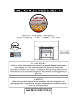
P61A Pellet Stove
The Label Pictured Is For Reference Only. For specic infor-
mation regarding testing and clearances, consult the actual
label on the rear of the stove.

4
P61A Pellet Stove
Safety Information 5
Installation 6
Venting 8
ESP Control 15
Automatic Operation 16
Manual Operation 19
Low Draft Voltage Adjustment 21
Maintenance 22
Troubleshooting 27
Fuel Specications 28
Mixing Corn with Pellets 29
Power Failure / Back-up 30
Options 31
Wiring Diagram 32
Specications 32
Warranty 33
Service Parts 35
Division of Hearth & Home Technologies, Inc
352 Mountain House Road
Halifax, PA 17032
Listed by: -Test Laboratories, Inc.
Report #: 135-S-22-4
Meets requirements of : ASTM E1509-04, ULC
S627-00, and ULC/ORD-C1482-M1990.
This appliance is also approved for installation into a
shop.

5
P61A Pellet Stove

6
P61A Pellet Stove
The P61A is bolted (1/4 x 1" hex head bolts) to the
skid to prevent movement during shipping.
To free the stove from the skid you must remove the
hold-down bolts in the rear of the pedestal base.
The rear cover panels are secured to the stove
with three bolts each. Two of the bolts need only be
loosened, not removed, to remove the panels. It is
recommended that the rear covers are installed after
the unit is in place and the vent pipe is installed, to
prevent contact with hot or moving parts.
Install the three rebricks vertically on the angle
bracket above the burnpot.
Install the cast iron ame guide on top of the burn
pot. Make sure that the ame guide is fully seated on
the vertical sides of the burn pot and that the back of
the guide rests against the body of the stove.
INSTALL EXHAUST VENT AT CLEARANCES
SPECIFIED BY THE MANUFACTURER. Most pellet
vent pipe requires a minimum of 3" of clearance
to combustible materials although some can be
installed at 1" clearance.
Rear Cover
Panels
Shipping Bolts
Note: These same holes
are used for securing the
stove in mobile home
installation.
Fig. 1
The room sensor is a small temperature sensor on
the end of a 60" wire. This sensor is installed much like
a standard wall thermostat. Because it is so small, it
can be hidden along the trim of a doorway or even up
the leg of a coffee table. There is a remote room sensor
port on the rear of the unit for easy external connec-
tion. Use standard 18-2 thermostat wire to extend the
distance to the desired location (50' maximum). The
room sensor should be installed in the location where
you want to control the temperature.
In most installations locating the room sensor behind
the stove near the distribution fan works well because
the sensor monitors the room air being drawn into the
distribution fan.
NOTE: Distances of more than 25 feet from the
unit or in another room are not recommended. The
room sensor is essential for the P61A's excellent ef-
ciency.
NOTE:
even if only installed on the rear of the
unit as a return air sensor.

7
P61A Pellet Stove
Place the stove on a noncombustible oor or on a oor
protector that extends a minimum of 6 inches to the front,
(measured from the glass) 6 inches to the sides and 1 inch
to the rear of the hopper. It is also recommended that oor
protection be installed under any horizontal venting and ex-
tending 2 inches beyond the vent measurement. Material used
for oor protection must be a minimum 3/8" of material rated
at 0.84k per inch. Another method for calculating oor protec-
tion is in R-value. Minimum permitted is 0.45 R. Example: 1"
thickness of a material is rated at 0.52 R, which would meet
the requirement.
Place the stove away from combustible walls at least as far
as shown in Figures 3,4 and 5. Note the difference in side wall
clearance with and without side shields.
Note that the clearances shown are minimum for safety
but do not leave much room for access when cleaning or
servicing.
Connect the power cord to a 120 V.A.C. 60Hz grounded
receptacle. (A surge protector is recommended to protect the
circuit board.) Also be sure that the polarity of the outlet that
the stove is plugged into is correct.
Prior to installing the ue pipe, connect a draft meter. (The
draft meter must have a minimum range of 0-.5.) Record the
rst reading. Connect ue pipe to stove and be sure all doors
and windows in the home are closed. Record the second
draft reading_______. If the second reading is more than .05"
lower than the rst reading, check for possible restrictions or
the need for outside air (see page 9). For more information
on the draft test procedure, refer to Page 21.
When installing this unit in a mobile home, several require-
ments must be followed:
1. The unit must be bolted to the oor. This can be done with
1/4" lag screws through the 2 holes in the base plate.
2. The unit must also be connected to outside air. See page
9.
3. Floor protection and clearances must be followed as
shown.
4. Unit must be grounded to the metal frame of the mobile
home.
Fig. 4
9" With Side Shields
13" Without Side Shields
Fig. 3
9" or 13"
9" or 13"
Fig. 6
Fig. 5
18"

8
P61A Pellet Stove
WARNING: Venting terminals must not be recessed
into a wall or siding.
NOTE: Only approved pellet vent pipe, wall pass-
throughs, and re stops should be used when venting
through combustible materials.
NOTE: Always take into consideration the effects
of the prevailing wind direction or other wind currents
that may cause yash and/or smoke when placing the
termination of the vent.
A. The clearance above grade must be a minimum
of 18".
B. The clearance to a window or door that may be
opened must be a minimum of 48" to the side, 48" below
the window/door, and 12" above the window/door.
(
)
C. A 12" clearance to a permanently closed window
is recommended to prevent condensation on the win-
dow.
D. The vertical clearance to a ventilated soft located
above the terminal within a horizontal distance of 2 feet
(60 cm) from the center-line of the terminal must be a
minimum of 18".
E. The clearance to an unventilated soft must be a
minimum of 12".
F. The clearance to an outside corner is 11" from
center of pipe.
G. The clearance to an inside corner is 12".
H. A vent must not be installed within 3 feet (90 cm)
above a gas meter/regulator assembly when measured
from the horizontal center-line of the regulator.
I. The clearance to service regulator vent outlet must
be a minimum of 6 feet.
J. The clearance to a non-mechanical air supply inlet
to the building or the combustion air inlet to any other
appliance must be a minimum of 48”.
K. The clearance to a mechanical air supply inlet must
be a minimum of 10 feet.
()
L. The clearance above a paved sidewalk or a paved
driveway located on public property must be a minimum
of 7 feet.
M. The clearance under a veranda, porch, deck or
balcony must be a minimum of 12 inches.
(
)
NOTE: The clearance to vegetation and other exterior
combustibles such as mulch is 36” as measured from
the center of the outlet or cap. This 36” radius continues
to grade or a minimum of 7 feet below the outlet.
Certain Canadian and/or Local codes or regulations
may require different clearances.
A vent shall not terminate directly above a side-
walk or paved driveway which is located between two
single family dwellings and serves both dwellings.
Only permitted if veranda, porch, deck, or balcony is
fully open on a minimum of 2 sides beneath the oor.
= Venting Terminal
= Air Supply Inlet
= Area where termination is not permitted

9
P61A Pellet Stove
Pellet venting pipe (known as PL vent) is constructed
of two layers with air space between the layers.
This air space acts as an insulator and reduces the
outside surface temperature to allow a clearance to
combustibles of 1 to 3 inches. The sections of pipe
lock together to form an air tight seal in most cases.
However, in some cases a perfect seal is not achieved.
For this reason and the fact that the P61A operates
with a positive vent pressure
Aluminum tape
can also be used for any joint that is 1 ft. or more from
the outlet of the stove.
We cannot emphasize enough, the importance
of sealing every seam and joint in the venting system
which is inside the home. Even the smallest pin hole
can leak and when it does you will smell wood smoke
or a creosote smell in the room. If this occurs check
for leaks. Leaks are easiest to see during start-up.
Alternatively you can use a smoke pellet to leak test
the venting before lighting your rst re.
T
without exhaust
blower operation. Negative pressure in the house will
resist this natural draft if not accounted for in the pellet
appliance installation.
Heat rises in the house and leaks out at upper levels.
This air must be replaced with cold air from outdoors,
which ows into lower levels of the house. Vents and
chimneys into basements and lower levels of the house
can become the conduit for air supply, and reverse
under these conditions.
Approved Pellet Vent Pipe- Widely Known As
"PL Vent",
= Positive Static Pressure
= Negative Static Pressure
+
+
-
+
-
Fig. 7
A combustion blower is used to extract the com-
bustion gases from the rebox. This causes a negative
pressure in the rebox and a positive pressure in the
venting system as shown in Fig. 7. The longer the
vent pipe and more elbows used in the system, the
greater the ow resistance. Because of these facts we
recommend using as few elbows as possible and 15
feet or less of vent pipe. The maximum horizontal run
should not exceed 48". If more than 15 feet of pipe
is needed, the interior diameter should be increased
from 3" to 4" because a larger pipe causes less ow
resistance.
The use of a starting
collar is not always necessary. The rst piece of pipe
must be secured, with at least 2 fasteners, to the ue
collar of the stove. The 2 screws provided are self-drill-
ing, however, drilling a 3/32" pilot hole for each screw
is recommended due to the material thickness.

10
P61A Pellet Stove
Outside air ex pipe
goes here.
Inlet Cover part#
1-10-08542
Flex pipe part#
1-00-08543 (25')
Per national building codes, consideration must be
given to combustion air supply to all combustion appli-
ances. Failure to supply adequate combustion air for all
appliance demands, may lead to back-drafting of those
and other appliances.
When the appliance is side-wall vented: The air in-
take is best located on the same exterior wall as the
exhaust vent outlet and located lower on the wall than
the exhaust vent outlet.
When the appliance is roof vented: The air intake is
best located on the exterior wall oriented towards the
prevailing wind direction during the heating season.
The outside air connection will supply the demands
of the pellet appliance, but consideration must be given
to the total house demand. House demand may con-
sume some air needed for the stove, especially during
a power failure. It may be necessary to add additional
ventilation to the space in which the pellet appliance is
located. Consult with your local HVAC professional to
determine the ventilation demands for your house.
To install outside air use 2 3/8" I.D. non-combustible
ex pipe. There is a break-away hole on the rear panel
of the stove which must be removed before connect-
ing the ex pipe. The pipe should be run outside and
terminate to the side or below the vent pipe outlet so
the ue outlet is more than 12" from the inlet cover. The
maximum length run of this pipe is 15 feet. If a longer run
is needed the size must be increased to 3". Inlet cover,
part number 1-10-08542 should be used to keep birds,
rodents, etc. out of the pipe.
You may choose to use the optional Direct Vent Wall
Passthrough Kit (part #1-00-677077) which incorporates
the venting passthrough and outside air inlet into one
component.
Direct Vent Wall Passthrough Kit
(part #1-00-677077)
To reduce probability of reverse drafting during shut-down conditions, Hearth & Home Technologies
strongly recommends:
• Installing the pellet vent with a minimum vertical run of ve feet, preferably terminating above the roof line.
• Installing the outside air intake at least four feet below the vent termination.
To prevent soot damage to exterior walls of the house and to prevent re-entry of soot or ash into the house:
• Maintain specied clearances to windows, doors, and air inlets, including air conditioners.
• Vents should not be placed below ventilated softs. Run the vent above the roof.
• Avoid venting into alcove locations.
• Vents should not terminate under overhangs, decks or onto covered porches.
• Maintain minimum clearance of 12 inches from the vent termination to the exterior wall. If you see
deposits developing on the wall, you may need to extend this distance to accommodate your installation
conditions.

11
P61A Pellet Stove
This method also provides excellent venting
for normal operation but requires the stove to be
installed farther from the wall. The vertical portion
of the vent should be three to ve feet high and at
least three inches from a combustible wall. This
vertical section will provide natural draft in the event
of a power failure.
If the stove is installed below grade be sure the
vent termination is at least 18" above grade. The
outlet must also be 1 foot from the house/building.
This method provides excellent venting for
normal operation and allows the stove to be in-
stalled closest to the wall. Two inches from the wall
is safe; however, four inches allows better access
to remove the rear panel. The vertical portion of the
vent should be three to ve feet high. This vertical
section will help provide natural draft in the event of
a power failure.
Fig. 8
3 ft.
to combustibles
Fig. 9
3 ft.
to combustibles
3 ft.
to combustibles
36" min
clearance to any
combustible
material
12" min. wall to outlet
3 ft.
to combustibles

12
P61A Pellet Stove
This method provides excellent venting for
normal operation. This method also provides
natural draft in the event of a power failure. If the
chimney condition is questionable* you may want
to install a liner as in method #7.
In some places in the US and Canada it is
required that the vent pipe extend all the way to the
top of the chimney.
*The chimney should be inspected and cleaned
before installing your stove. If you discover that the
chimney does not have a clay tile liner or has cracks
or aking of the tile liner you will need to install a
stainless steel liner within the chimney. In most cases
the inside diameter of this liner should be 4". Either
exible or rigid liner may be used for this purpose.
Refer to Method 6 & 7.
Be sure to design the venting so that it can be easily
cleaned.
This method provides excellent venting for
normal operation. This method also provides natural
draft in the event of a power failure. If the chimney
condition is questionable* you may want to install a
liner as in method #6.
In some places in the US and Canada it is
required that the vent pipe extend all the way to the
top of the chimney.
*The chimney must be inspected and cleaned
before installing your stove. If you discover that the
chimney does not have a clay tile liner or has cracks
or aking of the tile liner you will need to install a
stainless steel liner within the chimney, as shown
in Method 6 & 7.
The chimney must be sealed at the damper us-
ing a steel plate. Kaowool, mineral wool or other non-
combustible insulation is recommended above the
plate to reduce the possibility of condensation. The
connector pipe should extend through the smoke
chamber to the base or into the rst ue tile.
Be sure to design the venting so that it can be
easily cleaned.
Fig. 10
Fig. 11

13
P61A Pellet Stove
This method provides excellent venting for
normal operation. This method also provides natural
draft in the event of a power failure.
In some places in the US and Canada it is re-
quired that the vent pipe extend all the way to the top
of the chimney. The pipe or liner inside the chimney
should be 4" diameter.
In this method a cap should also be installed
on the chimney to keep out rain. Be sure to use ap-
proved pellet vent pipe ttings. Seal pipe joints with
silicone or aluminum tape in addition to the sealing
system used by the manufacturer. Pipe size should
be increased to 4" using this method.
This method provides excellent venting for
normal operation. This method also provides natural
draft in the event of a power failure.
In some places in the US and Canada it is re-
quired that the vent pipe extend all the way to the top
of the chimney. The pipe or liner inside the chimney
should be 4" diameter.
In this method a cap should also be installed
on the chimney to keep out rain.
Fig. 12
Fig. 13

14
P61A Pellet Stove
Through the ceiling vent, follow PL vent
manufacturers recommendations when using wall
and ceiling pass through.
Fig. 14
PL vent manufacturer's
fi r es t op sp a ce r an d
support
(See Page 7 for
corner installation
clearances)
It is recommended that outside
air be installed with this venting
conguration to reduce smoke
and creosote smell in the room
in the event of power failure.
Min. above ground level
18"
Storm collar
Flashing
3" min.
3" min.
12" min.
3" min.
Fig. 15
3" min.
No insulation or
other combustible
m a t e r i a l s a r e
a l l o w e d w i t h i n
3" of the p ellet
vent pipe. Unless
specified by the
pipe manufacturer
12" min. wall to outlet
36" min clearance to any
combustible material
Fig. 16

15
P61A Pellet Stove
Sets the maximum
feed rate.
Runs all motors at full
speed for one minute
to check operation.
Afterward the control
w i l l s i m u l a t e a
minimum burn and the
combustion blower will
remain on low, with the
distribution blower on
high.
Set to appropriate
Start-Up mode.
Distri b u t io n Bl o w e r
s p e e d a d j u s t m e n t
range.
L = low
H = high
V a r i a b l e s p e e d
anywhere between L
and H; although as the
stove temp. goes up ,
so does the low end of
the scale.
Allows you to adjust the room temperature in Room
Temp Mode using the outer scale marked in degrees
Fahrenheit. It also allows you to adjust the stove
temperature while in Stove Temp Mode using the inner
scale marked from 1 to 7.
Allows you to choose between
Room Temp Mode, Stove Temp
Mode, or OFF. Also allows you
to vary the distribution blower
speed by turning the knob to
the high or low side of each
mode.
Indicates power to the
control.
Indicates power to the
feed motor.
Indicates power to the
igniter.
Indicates power to
combustion blower.
Will be lit in either stove
or room temp mode
when pointer is not
within off position band
except after normal shut
down. Blinks to indicate
errors listed below.
Indicates power to
distribution blower.
Indicates that the ESP (Exhaust Sensing
Probe) has lost communication with the circuit board,
or has gone out of range more than allowed in a speci-
ed time. If the unit seems to be operating properly,
perform a manual reset*. If the code persists, contact
your dealer.
Can occur only in Room Temp Mode and
indicates Room Sensing Probe failed or not installed.
If a Room Sensing Probe is then installed, the status
light will automatically reset.
Indicates that
the unit has failed to light within the 36 minute start
cycle. To reset - Turn Mode Selector to "OFF", then turn
to either mode again.
: Indicates that the control has calculated poor
or incomplete combustion occurring for more than 50
minutes.
A six blink status may be set if the stove is allowed to
run out of pellets. To reset, turn mode selector to "OFF"
then back on to the desired mode. If the unit was not
out of pellets, see Troubleshooting section, Page 27,
for more details.
- disconnect power cord for a few
seconds and reconnect. If error still occurs call your
Dealer.
For dealer maintenance
only. Requires special DDM
monitor supplied to Harman
Dealers exclusively.

16
P61A Pellet Stove
This setting, see above,
will produce a room temperature of 70 degrees with the
distribution blower at medium speed.
The P61A is a fully automatic stove that features two
operating modes; and
. In Stove Temperature Mode, you
select a burn rate and the stove will remain at the same
burn rate regardless of the room temperature.
In the Room Temperature Mode the stove constantly
monitors the temperature in the room and adjusts the
size of the re and the heat output of the stove so that the
room is kept at a constant temperature. Room mode, in
the AUTO position, has the added advantage of turning
the stove off if no heat is required and turning the stove
on again when the room temperature drops below your
desired room temperature.
Most consumers use the stove in the Room Temperature
Mode because it is the easiest and most efcient method
of keeping the room at a given temperature. In the
Room Temperature Mode, the Room Sensing Probe
constantly monitors room temperature. As the weather
changes outside and your home needs varying amounts
of heat to be at a desired temperature, the stove will
automatically increase re size and heat output so
that a constant even temperature is maintained. If the
weather warms up and no heat is required, the stove
will gradually shut down. When the house cools down,
the stove will automatically bring the room temperature
to the precise temperature you desire.
In the Room Temperature Mode you can select either
for the using the igniter
toggle switch. When the toggle switch is in the Auto
position, the igniter, located inside the burn pot, is ready
to automatically light the re when required. When the
toggle switch set to the Manual position the stove can
be lit manually with either a gel or a wax type re starter.
(see lighting instructions on page 19.) With the igniter
toggle switch set in the Manual position the stove will
automatically adjust heat output, but the stove will not
automatically shut down if no heat is required. Instead it
will go to its lowest setting and remain there. The Manual
position on the igniter toggle switch lets you light the
stove manually, should the igniter fail for any reason.
Secondly if you are using the Harman battery back up
system, the Manual setting will prevent the stove from
turning off and on during a power failure, which would
drain the back up battery, and possibly cause damage
to the back-up or the stove.
In the Room Temperature Mode, the distribution blower
speed can be increased or decreased by adjusting the
Room Temp/Off/Stove Temp dial between L and H. As
output of the stove increases, the speed of the blower
will increase automatically to insure that more heat is
transferred out into the room. The distribution blower
will shut off as the room reaches the set temperature,
this will prevent overheating of the room.

17
P61A Pellet Stove
In the Stove Temperature Mode and with the igniter
toggle switch in the Auto position, the stove will light
automatically and can be adjusted to the desired setting
using the same temperature control dial as is used in
the Room Temperature Mode. The heat output and fuel
consumption will remain constant regardless of room
temperature. The settings from 1 to 7 on the inner ring
of the temperature dial provide for relative heat output
settings with 1 being low and 7 being the maximum.
In Stove Temperature Mode, the stove will not
automatically shut off unless the stove runs out of fuel
or is turned off.
Never pull the plug to shut down the stove. This will stop
the combustion blower and smoke will escape through
window and door gaskets.
When the ignitertoggle switch is set to manual in this
mode, the distribution blower will not turn on with a
temperature dial setting from 1 to 5. The advantage of
this mode is to allow the operator to have a large viewing
re without blowing extra heat into the room.
During operation, with the temperature dial set
at #4 or less, the distribution fan will not operate. A #4
on the temperature dial and a #5 on the feed adjuster is
approximately 80% output. It is not necessary to oper-
ate the distribution blower below this point. Therefore,
the control allows a higher burn rate ( a larger viewing
re) without an excess of hot air blowing into the room.
An example of when to use the Manual Stove Tempera-
ture Mode is if you want to watch a large re and the
room is already up to temperature. The Stove Tempera-
ture Mode allows you to have a larger re and a lower
sound level, without the distribution blower.
For most premium grade pellet fuels the Feed Adjuster
Knob should be set at 4. If higher ash fuels are used
the setting should be increased to 5 or 6. Also higher
settings are required if you would like to get the
maximum heat output from the stove. At the maximum
burn rate (with the temperature dial on 7/90° and the
feed adjuster at 6) there should be 1" or more of ash on
the front of the burn pot. If there is less than 1" of ash,
turn the feed adjuster knob down to a lower setting.
The best way to shut down the stove is to simply let it
run out of pellets. The stove will shut down automatically.
Alternatively, you can turn the Mode Selector to “off”.
This will cause the re to gradually die down and go out.
The re will not go out immediately and may take more
than an hour to fully shut down.
If the stove is left to run out of fuel, you may get a 6
blink status light. If this happens simply reset the control
board by turning the mode selector to OFF and back
ON.
The setting above will produce continuous maximum heat
output with the distribution blower at full speed.
The setting above will produce continuous medium heat
output with the distribution blower at low speed.

18
P61A Pellet Stove
Make sure the unit is plugged into a 120 VAC, 60
HZ electrical source. The power light should be the
only light lit.
1.
2. with pellets.
1
3. with scraper, if necessary.
5
4.
(for one 60 second cycle).
2
This will feed pellets into the auger tube and also
allow you to check the motors for operation.
5.
6. into the "AUTO"
position.
7. to the desired
temperature.
8. to Room Temperature or
Stove Temperature.
9. with pellets and as
required.
6
1. Fines are small pieces of broken pellets (sawdust). Fines do not
ow easily and often build up on the hopper funnel bottom angles.
You can push these nes into the feeder opening and then ll the
hopper with pellets. As the system works, they will be burned. Or
you can clean them out before lling the hopper.
2. The "TEST" cycle will operate the feeder motor for exactly one
minute. Turning to "TEST" again and again may charge too much
fuel into the burn pot causing excessive smoke on start-up.
3. The rebox low pressure switch will not allow the auger motor
or the igniter element to operate if the view door or the ash pan
door are open.
4. Adjust Feed Rate. If this is your rst re or you are trying different
pellets, set the feed adjuster to #4, Fig. 17. This is a conservative
number and will probably need to be increased. After you know a
feed rate setting that works well, use that setting. Remember, if your
feed rate is too high you may waste fuel.
5. This is usually a weekly maintenance procedure. Cleaning the
burn pot with the scraper with a small amount of new fuel in the
bottom is not a problem. First, scrape the ashes off the front of the
burn pot into the ash pan. Then, scrape the top surface of the burn
pot downward into the base of the burn pot. When the stove is ignited
these scrapings will be pushed out by the feeder and burned.
6. The ash pan can hold the ashes from approximately 1 ton of
premium fuel. This means the ashes will only need to be emptied
a few times each year.
7. Setting the feed adjuster # for maximum burn: With the unit
burning in "AUTO", turn to "Stove Mode" and put the fan on "H".
Set the Temperature Dial to #7. Allow the unit to burn for about 30
minutes and check ash on front of burn pot. Fig. 18. If the ash line
is larger than 1", turn the feed adjuster from #4 to #5. Allow another
30 minutes of burn time and check again. If , at #6 setting, a 1" or
less ash bed is not obtainable, it is not a problem. The 1" ash bed
is only a maximum burn rate and at most normal settings the ash
bed will be larger.
Fig. 17
See Hint #7.
Fig. 18
1"
Flame Guide

19
P61A Pellet Stove
The P61A Pellet Stove is capable of manual operation. This also allows the operator
to manually control operation during an emergency (i.e. igniter failure, when using a
502H battery backup, as opposed to the 512H, or when using certain generators.)
The unit can be switched between "AUTO" and "MANUAL" at any time during op-
eration.
The re will have to be lit with starting gel and a
match, or started automatically, see "Automatic Opera-
tion" on Page 16. Turn to "Manual" position when the
ignition cycle has started.
The difference between "AUTO" Room Temperature
Mode and "Manual" Room Temperature Mode is that
the re will not go out as the room temperature goes
above the control board setting. The unit can only go to
low burn and will remain there until it runs out of fuel or
until more heat is needed and the feed rate increases.
Feed rate adjustments and dial settings are the same
as "AUTO" settings.
The blower will shut off com-
pletely if the temperature on the ESP is too low.
The advantage of this mode is to allow the operator
to have a large viewing re without blowing extra heat
into the room.
During operation, with the temperature dial set at
#5 or less, the distribution fan will not operate. A #5 on
the temperature dial and a #5 on the feed adjuster is
approximately 80% output. It is not necessary to oper-
ate the distribution blower below this point. This control
setting allows a higher burn rate (a larger viewing re)
without an excess of hot air blowing into the room.
An example of when to use the Manual Stove Tem-
perature Mode is if you want to watch a large re and
the room is already up to temperature. The Stove
Temperature Mode allows you to have a larger re and
a lower sound level, without the distribution blower.
This setting will produce a large viewing re
without a distribution blower operating.
This
setting, see below, will produce a
room temperature of 70 degrees
with the distribution blower at
medium speed.

20
P61A Pellet Stove
Make sure the unit is plugged into a 120
VAC, 60 HZ electrical source. The power light
should be the only light lit.
.
No. 4 is good for most pellets.
4
This will reset con-
trol and start the combustion motor.
(Do Not Over Fill).
Stir gel
into pellets for fast lighting.
Operation will begin when the re reaches
the proper temperature.
3
1. Fines are small pieces of broken pellets (sawdust). Fines do not
ow easily and often build up on the hopper funnel bottom angles.
You can push these nes into the feeder opening and then ll the
hopper with pellets. As the system works, they will be burned. Or
you can clean them out before lling the hopper. As the system
works, they will be burned.
2. The "TEST" cycle will operate the feeder motor for exactly one
minute. Turning to "TEST" again and again may charge too much
fuel into the burn pot causing excessive smoke on start-up.
3. The rebox low pressure switch will not allow the auger motor
or the igniter element to operate if the view door or the ash pan
door are open.
4. Adjust Feed Rate. If this is your rst re or you are trying different
pellets, set the feed adjuster to #4, Fig. 19. This is a conservative
number and will probably need to be increased. After you know a
feed rate setting that works well, use that setting. Remember, if your
feed rate is too high you may waste fuel.
5. This is usually a weekly maintenance procedure. Cleaning the
burn pot with the scraper with a small amount of new fuel in the
bottom is not a problem. First, scrape the ashes off the front of the
burn pot into the ash pan. Then, scrape the top surface of the burn
pot downward into the base of the burn pot. When the stove is ignited
these scrapings will be pushed out by the feeder and burned.
6. The ash pan can hold the ashes from approximately 1 ton of
premium fuel. This means the ashes will only need to be emptied
a few times each year.
7. Setting the feed adjuster # for maximum burn: With the unit
burning in "AUTO", turn to "Stove Mode" and put the fan on "H".
Set the Temperature Dial to #7. Allow the unit to burn for about 30
minutes and check ash on front of burn pot. Fig. 21. If the ash line
is larger than 1", turn the feed adjuster from #3 to #4. Allow another
30 minutes of burn time and check again. If , at #6 setting, a 1" or
less ash bed is not obtainable, it is not a problem. The 1" ash bed
is only a maximum burn rate and at most normal settings the ash
bed will be larger.
Fig. 20
Fig. 19
Fig. 21
1"
See Hint #7.
/