Page is loading ...

Field-Installable Pre-Polished Optical Fiber Connectors
www.signamax.com
999 N.W. 159
th
Drive
Miami, FL 33169
800.446.2377
305.944.7710
Fax: 305.949.4483
Copyright 2007 Signamax/AESP, Inc. All rights reserved
Signamax Connectivity Systems is a trademark of AESP, Inc.
Specifications subject to change
Connectivity Solutions
INSTALLATION INSTRUCTIONS
FPC
-
02 Rev.A JAN
-
2016
1
The following installation instructions are intended to be
used when installing the following Signamax optical
Connectors and the optional fiber Jig Assemble Tool:
FPCxx-SCxx-02
FPCxx-LCxx-02
NOTES:
1. Optical fiber connectors shown in these instructions used for
example purpose only; actual product maybe slightly different in
dimensions and design detail.
2. Picture of tool used for example purpose only; actual tools may
differ from those shown.
3. All illustrations are not to scale
Make sure you have all necessary
tools for the job:
• Cable jacket stripping tool
• Optical fiber stripping tool
• Optical fiber cleaving tool
• Lint-free cloth wipes
• Optical fiber cleaning fluid
• Metric ruler and marker pen
WARNING:
• Wear safety glasses before handling
optical fiber to protect the eyes.
• Never look into the end of a connector or
an optical fiber which may have a laser
coupled to it.
1
2
3
4 5
Identify components of the connectors kits:
1: 250-µm Tube 2: Fiber Connector 3: 900-µm Boot
4: Jig - Connector Holder 5: Jig -Fiber Holder
( 4 & 5 Sold Separately )
3
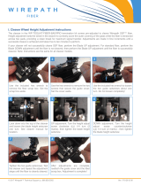
Be sure there is no space between
the wedge and connector, if there is,
push the wedge and connector
together to realign.
Set connector tightly onto
ridge of “U” shaped Jig. (#4)
Open covers 1, 2, 3. Make sure
the guide is not visible. If visible,
push the back-end into the fiber
holder.
5
Place the 900-µm boot on the fiber cable, if applicable
then slide 250-µm tube on the fiber. Angle cut first.
!
2
Remove the fiber guide on the cleaver by using the
allen key located at the bottom of the cleaver and
turning counter clock-wise.
4

Field-Installable Pre-Polished Optical Fiber Connectors
www.signamax.com
999 N.W. 159
th
Drive
Miami, FL 33169
800.446.2377
305.944.7710
Fax: 305.949.4483
Copyright 2007 Signamax/AESP, Inc. All rights reserved
Signamax Connectivity Systems is a trademark of AESP, Inc.
Specifications subject to change
Connectivity Solutions
INSTALLATION INSTRUCTIONS
FPC
-
02 Rev.A JAN
-
2016
Place the Jig with the
fiber onto cleaver
8
9
While hold the jig, cleave the
fiber.
Set the fiber holder to the guide
rail. Be sue the fiber aligns with
the U-groove.
Slide the fiber forward holder
slowly until it stop.
Open the middle cover and continued moving
forward until you hear a “click” sound. Small
amount of bending is normal in the middle.
Open lock lever and push
the sides to release and
remove the wedge.
Open cover 1 and 2.
Remove connector from jig and
slide boot up until it clicks onto
the connector
Verify good termination by using
a visible light source.
Good Connection: Bad Connection:
No Light Visible Light
10
11
12
13
14
15
Slide the tube up and set the fiber
and tube into the holder using the
above dimensions. Once fiber is
set, close the first 2 covers starting
the one closest to the fiber.
7
Check your cleaved
fiber length by placing
Jig and Holder together.
6
Strip 35 mm of 900- and 250-µm coating from fiber and
Clean the fiber with a lint-free wipe and fiber preparation fluid
By re-inserting the wedge
into the connector, fiber
connector could be re-
terminated.
!
/


