Page is loading ...

Technical Support
1-800-248-0892
Ext. 2
1
MN-202
(08104)
ECN3471
P/N 25802 (Four Point Leveling Option)
by
Please read these instructions completely before proceeding with the installation.
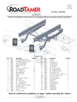
Figure 1
Inflation
Valve
(Already
installed)
Inflation
Valve
(Already
installed)
REAR
BELLOWS
(Already
installed)
Inflation
Valve
(Already
installed)
Inflation
Valve
(Already
installed)
FRONT
BELLOWS
(Already
installed)
Ground
Front View of Panel
EXISTING SYSTEM
4 POINT LEVEL ADDITION
COMPRESSOR
FEMALE
CONNECTOR
FUSE/
FUSE HOLDER
TO A KEYED
POWER SOURCE
SOLENOID
SOLENOID
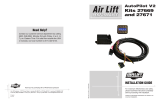
Butt Connector
Air Inlet
filter
Straight
Push Lock
Fitting
PDPD
www.airliftcompany.com

Technical Support
1-800-248-0892
Ext. 2
2
From
Solenoid
To PanelTo Solenoid
From
C
ompressor
To Air
Spring
To Panel
To Air
Spring
Template For Drilling Holes
Original Jumper
Configuration
New Jumper
Configuration
white wire +
black wire
Remove
Old Wires
Install
New Wires
white wire +
black wire
Figure 2
I. Mounting the Gauge Panel
NOTE: All preassembled gauge panels have been 100% leak and function
tested. Do not attempt to tighten, loosen or adjust any fittings or connections.
This will likely cause a leak or malfunction and void the warranty.
1. Select a convenient, sturdy mounting location for the gauge panel,
usually next to the existing gauge panel (Figure 1).
2. Using the gauge panel mounting bracket as a template, mark the
mounting screw hole locations. Center punch and drill two
1
/8"
diameter holes.
3. Position the gauge panel to the mounting surface and secure with 2
self-tapping screws.
II. Mounting the Solenoid
1. Install the fittings to the solenoids as shown in Figure 2. One port
requires the use of
1
/8" N.P.T. straight fitting, while all the other ports
take male run tees (Figure 2).
2. Select a convenient mounting location for the solenoid, which provides
protection from the elements. Using the template provided in Figure
3, center punch the holes, remove the template, and drill two
3
/16"
holes. Use the supplied hardware for solenoid mounting (Figure 3).
III. Wiring the Electrical Connections
1. Two new jumper wires are provided with this kit to replace the ones
on the existing gauge panel. Remove the leads from the compressor
and from the power source, noting which terminal on the gauge
panel each lead is connected to. Remove the old jumper wires and
install the new ones (Figure 4). Connect the leads from the power
source and the compressor.
2. Determine the amount of wire needed to connect the two gauge
panels. Cut and strip the wire, attaching female blade connectors on
both ends. Install one end on the male blade connector attached to
the top center terminal on the original gauge panel, and install the
other end on the male blade connector attached to the bottom center
terminal on the new gauge panel (Figure 5).
3. Determine the length of the second wire need to connect the 2 panels.
Strip both ends and attach female blade connectors, in this case
installing them on the male blade connectors on the lower left terminal
of the original gauge panel and the lower right terminal of the new
gauge panel (Figure 5).
4. Route the small red power wire for the illuminated gauge to an
accessory power source. Attach the small black wire to an adequate
ground.
IV. Wiring the Solenoids
1. Determine the left and the right solenoids. One wire from each needs
to be grounded and one routed to the toggle switch on the gauge
panel.
2. Determine a good ground and cut one wire from each solenoid to
reach the ground area. Use one of the self tapping screws to ground
the ring terminal.
3. Measure the length of wire necessary to route from solenoid to gauge
panel. If it exceeds 24", use a butt connector and additional wire.
Attach a female blade connector to each wire and connect the left
one to terminal 4 on the toggle switch and the right one to terminal 6
(Figure 6).
Figure 4
Figure 3

Technical Support
1-800-248-0892
Ext. 2
3
Gauge Panel Relay Switch Diagram
New
Gauge
Panel
Existing
Gauge
Panel
To Compressor
(Already Installed)
To Power Source
(Already Installed)
NOTE:
New Jumper
Wires
To New Solenoids To Existing Solenoids
Figure 5
Figure 6
V. Connecting the Air Lines
1. Remove the air pressure from all air cylinders. Take the core out or
use a tire gauge to bleed off the air pressure.
2. Note: Keep air line away from heat (exhaust system, etc.) and moving
chassis components. Secure air line to frame with nylon tie straps
provided.
3. Use a standard tube cutter, a razor blade, or very sharp knife to cut
the air line already installed between each air cylinder and inflation
valve. A clean square cut will ensure against leaks. Install a tee
(Figure 8). Follow this procedure for air line leading to the other air
spring and inflation valve.
4. Measure the distance from the left hand tee to the driver’s left side
solenoid. Cut the air line to the proper length and install on last leg
of tee previously installed between the air spring and the inflation
valve.
5. Route the left hand air spring air line along the frame and secure with
nylon tie straps. Push the air line into one leg of the tee on the left
solenoid (Figure 2 & 8).
6. Measure distance between left hand solenoid and control panel. Cut
sufficient air line and attach one end into last leg of tee on left solenoid
and route air line to left hand gauge and control panel (Figure 1 & 2).
7. Repeat steps for right hand side of the vehicle.
8. Select a point in the air line between the compressor and the original
solenoids, at which to install a tee. This will provide air for the new
set of solenoids (Figure 7).
9. Cut the air line and install a tee (Figure 8).
10. Measure distance between the new solenoids and the tee. Cut a
length of air line and install one end on the last leg of the tee.
11. Route air line to tee fitting installed in one of the ports in the solenoids.
Attach air line as shown in Figure 8.
12. Use sufficient air line to connect the to both solenoids. Caution should
be used not to kink air line. Attach air line as shown in Figure 8.
13. Turn on ignition switch. Push toggle switch to the left and watch
pressure increase on the left air gauge. Inflate to 100 p.s.i. Push
switch to the right and inflate right side to 100 p.s.i. Inspect each
connection with a soap and water solution. If a leak is found in the
fittings, reduce air pressure to zero and tighten threaded connections
or remove air line, cut off one inch and reinstall.
VI. Using the Level Inflation Control
Your motorhome is equipped with front and rear air springs. The following
procedure is a guide to assist in leveling the motorhome to provide the
best possible ride and handling.
1. Fill the air springs to 100 p.s.i. maximum. The pressure can be
increased from the dash control or the inflation valves located just
ahead of the rear wheels.
2. Position the motor home in a level spot and reduce the pressure on
the high side until the vehicle is square side to side. This will
compensate for the extra load created by holding tanks, generators
and other weight placement.
3. Both units can now be reduced equally to level the motor home from
front to rear. Generally, the vehicle will ride best when the rear springs
are slightly arched.
3
2
1
6
4
5
To Compressor
To Driver Solenoid
To Passenger Solenoid
To Driver
Solenoid
To Passenger
Solenoid
To Fuse and
Accessory Connection
in Fuse Panel
NOTE: Shaded wires are factory-installed jumper
wires, and should not be altered in any way
Existing
Solenoids
New
Solenoids
Install
Tee Here
Compressor
Figure 7

Technical Support
1-800-248-0892
Ext. 2
4
“The Choice of the
Professional Installer”
For Technical Assistance call 1-800-248-0892
Thank you for purchasing Air Lift Products
Mailing Address: Street Address:
AIR LIFT COMPANY AIR LIFT COMPANY
P.O. Box 80167 2710 Snow Rd.
Lansing, MI 48908-0167 Lansing, MI 48917
Local Phone: (517) 322-2144
Fax: (517) 322-0240
http://www.airliftcompany.com
Printed in the USA
4. Start with a higher pressure and decrease in five pound increments
to determine the best ride and handling for your particular vehicle.
5. Increases in pressure can be made to compensate for additional
load and trailers, etc. Higher pressures can be used when the vehicle
is in storage to relieve the leaf springs.
VII. Operating from the Cab
The air springs should be inflated to the specified air pressure as discussed
in the air spring inflation procedure.
Whenever load and weight distribution change, simply adjust the pressure
in the air springs to maintain a level vehicle. Through use of the level
control system the air springs can be used to compensate for an uneven
campsite and uneven load distribution. The air pressure is manually
controlled individually by the control panel located on the dash.
1. To inflate the air springs and raise that side of the motor home, depress
the toggle switch on the control panel. The compressor will turn on
automatically to increase the pressure as indicated on the gauge.
Once the desired pressure is reached release the button and the
compressor will shut-off (Figure 9).
2. To deflate the pressure and lower that side of the motor home, depress
the down button to deflate to desire pressure (Figure 9).
VIII. Troubleshooting
Check the inflation pressure weekly, air spring bellows will permeate (loss
of pressure through the rubber wall) at the approximate rate of 3-4 p.s.i. per
week. Leakage at a higher rate indicates a leak.
To find a leak:
1. Inflate the system to 100 p.s.i.
2. Spray all fittings with a solution of
1
/5 dish soap to
4
/5 water.
a. Check inflation valve: valve core and air line connections. If leak
is found in the valve core, tighten. It may be replaced with standard
Figure 8
Figure 9
Toggle Switch
Deflate Buttons
tire valve core. Fittings sometime only need tightening.
b. Check elbow fitting where threaded into bellows (all threaded connections must have pipe sealant applied) and air line
connection. If a leak is found where elbow is threaded into bellows, remove the fitting and clean thoroughly and apply
fresh liberal coat of pipe sealant. If a leak is found in the barbed fittings, reduce air pressure to zero and tighten threaded
connections or remove air line, cut off one inch, and reinstall.
3. Spray bellows to determine if leak exists. The bellows are not repairable and must be replaced if a leak is found in them.
4. If leak still cannot be found deflate and remove entire unit. Inflate to 15 p.s.i. only and submerge in water.
5. If leakage is suspected in the control panel, inflate the system to 100 p.s.i. and follow steps above. The fittings at the tee and
back of the control panel should also be checked with soapy solution. Most leakage can be cured by disassembly,
inspection and reassembly of fittings.
6. If compressor fails to function, check 20 amp fuse and ground connection. Repair and replace as necessary.
7. If electric motor runs, but compressor doesn’t function check to make sure solenoid valves are opening correctly.
Cut off excess air line squarely. Install the air line into the
fitting. Push the cut end of the air line into the self-locking
fitting as far as it will go while slightly turning. A definite
click can be heard and/or felt when the air line is seated.
Air line should go in approximately
9
/16".
/