Page is loading ...

Customer Service
1-800-248-0892
1
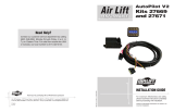
Check Valves
Low Pressure
Sensors
Harness #2
Harness #1
Panel Assembly
Fuse Box
Air Springs
(Previously Installed)
Power Wire
Power Wire
Fuse Adapter
In Line
15 AMP Fuse
Firewall
Grommet
Ground
Compressor
This kit is designed to operate between 5 and 100 p.s.i.
This installation should be done after the Air Spring kit has been installed.
If you have any questions, please call our Technical Service number: 1-800-248-0892.
by
With Low Pressure Sensors P/N 25812
MN-338
(04302)
ECN4031
FIGURE 1
Adapter #1
Adapter #2
Adapter #3 *
Adapter
Fuse
* Uses 3/16 (smaller) Female Push On Connector
INSET A
All pre-assembled gauge
panels have been 100%
leak and function tested.
Do not attempt to tighten,
loosen, or adjust any
fittings and connections.
This will likely cause a leak
or malfunction and void the
warranty.

Customer Service
1-800-248-0892
2
STEP BY STEP INSTALLATION (REFER TO PAGE 3 FOR FIGURES 2–4)
As an exclusive feature from AIR LIFT you will find a completely preassembled wiring harness (2 coils), dual gauge
panel, and the compressor unit. There is no need to cut, solder, crimp, or measure. (Figure 1)
All pre-assembled gauge panels have been 100% leak and function tested. DO NOT attempt to tighten,
loosen or adjust any fitting or connection. This will likely cause a leak or malfunction and void the
warranty.
All of the electrical connections are matched by male to female push in terminals. All of the air line connections
will be white to white, green to green, indicated by the color band. The color band also serves as a reference point
for installing the air line into the fitting. Properly installed, the front edge of the color band should be against the
collar of the fitting (Figure 2 & 3).
Do not cut, trim, modify, or disassemble the harness. If you have excess length, simply coil it up and secure out of
the way with the provided tie straps.
We recommend that you install the air spring kit first.
1. Install the gauge panel. Select a convenient mounting location that has a rigid surface that will provide for a
sturdy mounting surface. The bottom edge of the dash on either side of the steering wheel is a good location.
Use the black self tapping screws to attach the panel to the selected location.
2. Now install the compressor unit. Refer to the Recommended Compressor Location list included with this kit.
Hold the compressor in the recommended location and use the provided silver self tapping screws to attach
the mounting brackets to the vehicle. In some cases the mounting area does not allow enough room to use
a drill to drive the screws in. It will be necessary to use the mounting brackets as a template to drill 13/64"
holes through the frame first and then use a 7/16" nut driver to install the self tapping screws. NOTE: Attach
the ground wire to one of the screws (Figure 1).
Box Frames-In most cases the frame section will not be wide enough to mount the compressor legs flat to the
rail. It may be necessary to bend the mounting brackets into a 90 degree angle to allow the brackets to attach
to the side and bottom of the frame rail (Figure 5). The compressor mounting legs can be bent by putting the
bracket into a vise. Bend it by using a crescent wrench or tapping it lightly with a hammer, into a L shape.
CAUTION-Do not drill any holes into the frame or the floor board before checking for hydraulic lines, gas lines
and/or electrical wires that may need to be moved aside. Also, when attaching to the floor board, it is important
to check where the screws protrude through the floor board. It may be necessary to trim or cover the top of
the screws inside the vehicle. A sealer should be used around the screw to prevent the elements from entering
the cab area.
3. Now connect Wiring Harness #1 to the back of the gauge panel. With your thumb against the front side of
the switch, connect the wire by pushing the female connectors onto the blade connectors on the switch. Match
the air line by the color band on the air line to the color band on the tees. Push the air lines onto the T fittings
until the air line completely covers the barb (Figure 2). Some lubrication on the air line will ease pushing the
air line over the barb. Do not connect the power wire at this time.
Wiring Harness #1 also connects the gauge panel to the Low Pressure Sensor assemblies. The Low Pressure
Sensors protect the air springs from failure due to low pressure in the unloaded condition. These sensors are
pre-set to maintain a MINIMUM pressure of 10 psi in the air springs. This is accomplished by sensing the
pressure in each spring and turning on the compressor if the pressure should fall below 10 psi. NOTE: The
Low Pressure Sensors are pre-assembled onto Wiring Harness #1. The sensors should be located under the
dash inside the vehicle and secured with the provided tie straps.
4. Connect the check valves and power wire on Harness #2 to the compressor as shown in Figure 4. DO NOT
OVERTIGHTEN THE CHECK VALVE CONNECTOR - HAND TIGHT IS SUFFICIENT.

Customer Service
1-800-248-0892
3
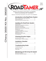
White Banded
Air Line
White
Banded Tee
No Tape
on Tee
Harness #1
No Tape
on Air Line
Figure 2
Figure 3
Figure 4
Figure 5
White banded
air line to white
banded Tee.
No tape air line
to no tape tee.
Harness #1
Harness #2
Gauge Side
Compressor Side
Power (Red) Wires

Customer Service
1-800-248-0892
4
For Technical Assistance call 1-800-248-0892
Thank you for purchasing Air Lift Products
Mailing Address: Street Address:
AIR LIFT COMPANY AIR LIFT COMPANY
P.O. Box 80167 2727 Snow Rd.
Lansing, MI 48908-0167 Lansing, MI 48917
Local Phone: (517) 322-2144
Fax: (517) 322-0240
4
Route Wiring Harness #2 from the compressor. Use existing grommets in the floorboard or firewall to route
the Harness from the compressor to the Low Pressure Sensors on Harness #1. In some cases a hole may
have to be drilled to allow access for the Harness. Drill a 1" diameter hole and install the provided grommet.
It will be necessary to seal any grommets or holes that have been cut, drilled or removed so as not to allow
elements to enter the cab area of the vehicle.
When routing Wiring Harness #2 from the compressor, it should NOT be routed so as to lay on, or near, the
exhaust pipe/muffler/catalytic convertor of the vehicle. Routing along the top of a crossmember or over a heat
shield is the recommended way of routing the harness.
5. Now connect Wiring Harness #2 to Wiring Harness #1 inside the vehicle. You need only to connect the red
wire from Harness #2 and the banded air lines to the Low Pressure Sensors. See Figure 3 for air line and
electrical connection.
6. The next connection is between each air spring and the air line T fitting located just ahead of the check valves
in Harness #2 (Figure 1 & 4). With the Air Springs deflated, use a hose cutter, a razor blade, or very sharp
knife to cut the air line already installed between the air springs and the inflation valves. Install the provided
T fittings in each air line (Figure 1). Push the air line into each leg of the T until you feel a definite click. the
line should go in 9/16". Connect a single length of air line to the open leg of each tee. Bring each of the
lines to the T fittings in Harness #2 just in front of the check valves and connect as shown in Figure 4. Route
the air line across the chassis from the far side over the exhaust system heat shields and along the
frame up to the compressor. Avoid heat sources, sharp edges and tight bends.
7. Now connect the power wire from Harness #1. Route it to the vehicle fuse box. Use a test light to determine
which open terminal (accessory, etc.) works only when the key is in the on or accessory position (or refer to
the owners manual for an available accessory fuse). The terminal should have an amperage rating equal to
or higher than the 15 amp in-line fuse. Connection to the fuse terminal will depend on what type of fuse your
vehicle uses. If your vehicle uses the barrel type fuse, use adapter #1. If you have the standard spade type
fuses, use adapter #2. Many late model vehicles use a smaller spade type fuse which requires adapter #3 -
see INSET A on front page. If adapter #1 or #2 are used, it will be necessary to cut off the 1/4" female
connector attached to the power wire and crimp the smaller 3/16" female connector supplied with this kit.
NOTE: Connect adapter to HOT side of the fuse (use a test light to determine). With the ignition on, the
compressor will turn on and fill the system to 10 p.s.i. before shutting off.
8. Press the off/on button to inflate both air springs and use the small deflate button to adjust the pressure.
Inflate to 30 p.s.i. (20 p.s.i. for AirLift 1000 kits). Check all fittings and inflation valve cores with
a soapy water solution for leaks.
9. Recheck air pressure after 24 hours. A 2-4 p.s.i. loss after initial installation is normal. If pressure
has dropped more than 5 p.s.i., re-test for leaks with soapy/water solution. Please read and follow
the Maintenance and Operating tips in the installation manual that came with your air spring kit.
If the compressor runs continually or often, there is most likely a leak. Disconnect the compressor at the
fuse box and test for leaks with a soapy water solution.
Never run compressor longer than 4 minutes continuously. Allow at least 5 minutes for cool down before
starting compressor again.
/