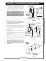
Air Lift Performance 39010 is a vehicle suspension system that enhances your driving experience by providing automatic load leveling, improved handling, and increased ride comfort. It features axle beams, frame brackets, and a panhard rod for precise vehicle alignment. The air management system maintains the vehicle's ride height within ½", ensuring a smooth and controlled ride regardless of the load.
Air Lift Performance 39010 is a vehicle suspension system that enhances your driving experience by providing automatic load leveling, improved handling, and increased ride comfort. It features axle beams, frame brackets, and a panhard rod for precise vehicle alignment. The air management system maintains the vehicle's ride height within ½", ensuring a smooth and controlled ride regardless of the load.


-
 1
1
-
 2
2
-
 3
3
-
 4
4
-
 5
5
-
 6
6
-
 7
7
-
 8
8
-
 9
9
-
 10
10
-
 11
11
-
 12
12
-
 13
13
-
 14
14
-
 15
15
-
 16
16
-
 17
17
-
 18
18


Air Lift Performance 39010 is a vehicle suspension system that enhances your driving experience by providing automatic load leveling, improved handling, and increased ride comfort. It features axle beams, frame brackets, and a panhard rod for precise vehicle alignment. The air management system maintains the vehicle's ride height within ½", ensuring a smooth and controlled ride regardless of the load.
Ask a question and I''ll find the answer in the document
Finding information in a document is now easier with AI
Related papers

Other documents
-
Air Lift 59536 Installation guide
-
-
-
-
-
-
Ridetech 19999001 Installation guide
-
-
Havis-Shields KK-X-ST-RP User manual
-