Page is loading ...

BY
MN-75
(12612)
ECN1965
1. Jack up front end of vehicle and place safety stands under
axle. Remove front wheels and lower shock absorber
attaching bolts.
2. Remove the upper spring retaining bolts (Figure 1, Item 1)
and strap. Lower axle or raise body until the spring is loose
in the upper seat. CAUTION: Do not strain flexible
hydraulic brake line. Remove brake line bracket attaching
bolt on axle if necessary.
3. Rotate coil spring in lower spring seat beyond locking tabs
to allow spring removal (Figure 1, Item 2). On some
models, it may be necessary to loosen lower spring seat
retaining bolts.
4. A template is provided to locate a hole in the upper spring
seat for valve stem access. The same template is used for
both left and right sides. Fold template along dotted line.
Place under right hand upper spring seat with type facing
downward, right hand arrow forward.
5. Place 3/8” capscrew in template and through outer retaining
strap hole. Insert another 3/8” capscrew in one of the inner
holes that align with the inner retaining strap hole in the
spring seat.
Hole “A” is used on 1973 and up.
Hole “B” is
used on 1966 - 1972.
6. Center punch and drill a 1/2” hole at forward star marked
R.H.S. Repeat this procedure for left hand side using other
star location.
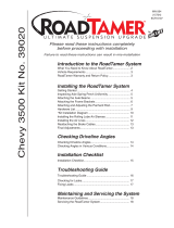
7. Insert air cylinder, stem up, into bottom of coil spring. Push
cylinder completely to the top.
8. Replace coil spring in lower spring seat, insuring that it is
under the retaining tab (Figure 1, Item 2).
9. Install the upper protector with the offset, smaller hole over
the valve stem and centered on the cylinder (Figure 2).
10.Raise axle or lower body to position coil spring into upper
spring seat (Figure 2).
11.Install the upper coil retaining strap. Replace the inner 1”
long bolt from the upper coil retaining strap with the 3/4”
long bolt provided in the package (Figure 2, Item 1).
12.Tighten lower spring seat retaining bolts to specifications if
loosened in step 3.
13.Insert lower protector between turns of the coil spring and
push firmly into lower spring seat (Figure 2).
14.Rotate cylinder to align valve stem with drilled hole in upper
seat.
2
1
3
Valve Stem
1
Upper
Protector
Lower
Protector
Figure 1
Figure 2
P/N 80523
ECR 8167

2
15.Slowly lower body or raise axle until cylinder contacts upper
and lower spring seats. Care should be taken to guide valve
stem in the proper location (Figure 1, Item 3).
16.Replace lower shock absorber attaching bolts and tighten.
17.Determine air line routing. A tee air line installation can be
used unless weight of vehicle varies from one side to the
other and unequal pressures are needed to correct
suspension alignment and level vehicle. Dual air lines are
used in this case. CAUTION: Avoid areas which may cause
failure of the air line. For example: battery, exhaust, engine,
radiator, and moving parts such as steering, suspension and
cables.
18. Proceed with desired air line routing (Tee or Dual).
AIR LINE INSTRUCTIONS
CAUTION: LEAVE SUFFICIENT AIR LINE SLACK TO
PREVENT ANY STRAIN ON FITTINGS DURING AXLE
MOTIONS.
TO PREVENT AIR LINE FROM MELTING, KEEP IT AT LEAST
TWELVE INCHES FROM EXHAUST SYSTEM, ENGINE AND
HEAT SOURCES. CAUTION: AVOID AREAS WHICH MAY
CAUSE FAILURE OF THE AIR LIN
E. FOR EXAMPLE:
BATTERY, EXHAUST, ENGINE, RADIATOR, AND MOVING
PARTS SUCH AS STEERING, SUSPENSION AND CABLES.
TEE AIR LINE CONNECTION:
A. Find desired tee location on the frame rail or radiator core
support bracket (Figure 5).
B. Determine and cut adequate length of air line to reach from
tee to left and right side on air cylinders.
C. Connect the air line to the two opposite legs on the tee (Figure
4).
D. Route air line to left and right air springs, generally along inner
fender panel or frame rails (Figure 5).
E. Slide air line clamp onto the air line. Push the air line over the
barbed end of straight fitting. Compress the ears on the air
line clamp with pliers and slide it down to cover the barbed
section (Figure 4). Repeat for other side.
F. Connect the straight fitting to the right & left air springs and
tighten securely (Figure 3).
G. Select a location for inflation valve in the hood release, front
bumper, fender flange or behind the license plate, assuring
that the valve will be protected and accessible with an air
hose.
H. Connect the remaining air line over the last fitting on
tee and
route along frame to desired inflation valve location. Attach air
line to chassis with plastic straps or wire.
I. Drill a 5/16” hole for inflation valve and mount as illustrated
(Rubber washer is for outside weather seal (Figure 7).
J. Connect the air line to the inflation valve (Figure 6).
K. Continue with step 19, page 3.
A
B
C
Use this procedure for all air line connections:
A. Slide air line clamp onto the air line
B. Push the air line over the barbed
stem.
C. Compress the ears on the air line
clamp with pliers and slide it forward to fully
cover the barbed section.
Figure 3
Figure 5

Option 1
Option 2
Figure 8
3
DUAL AIR LINE CONNECTION:
A. Select a location for the inflation valves in the rocker
panel flange or by hood release assuring that each
valve will be protected and accessible with an air line.
B. Determine and cut adequate length, not longer than 90”
of air line to reach from valve location to left side air
cylinder.
C. Slide air line clamp onto the air line. Push the air line
over the barbed end of straight fitting. Compress the
ears on the air line clamp with pliers and slide it down
to cover the barbed section (Figure 4). Repeat for other
side.
D. Connect the straight fitting to the right & left air springs
and tighten securely (Figure 3).
E. Route air line along frame or under fender panel to
desired inflation valve location (Figure 8). Attach air line
to chassis with plastic straps or wire.
F. Drill 5/16” hole for inflating valves and mount as
illustrated (Rubber washer is for outside weather seal,
Figure 7).
G. Connect the air line to the inflation valve.
H. Repeat process for other side.
I. Continue below with step 19.
19.Replace front wheels and return vehicle to normal
st
anding height.
20.Inflate cylinders to 50 psi air pressure. Test for air leaks
by applying a liquid soap and water solution to all valve
cores, fittings and connections. Adjust pressure down
until vehicle is visually level and for best ride comfort.
21.Recheck air pressure after 24 hours. A 2-4 psi loss after
initial installation is normal. If pressure has dropped
more than 5 lbs re-test for leaks with a soapy water
solution.
* Read Maintenance/Operation for proper care of your air
cylinders on page 4.
Hex Nut
Rubber
Washer
Flat
Washer
Lock
Washer
Hex Nut
Inflation
Valve
Air Line
Vehicle Bumper
or Body
Air Line
Clamp
Figure 7
Figure 6


4
MINIMUM AIR PRESSURE
10 P.S.I.
MAXIMUM AIR PRESSURE
50 P.S.I.
Thank you for purchasing Air Lift Products
AIR LIFT COMPANY
P.O. BOX 80167
Lansing, MI 48908-0167
FOR TECHNICAL ASSISTANCE CALL 1-800-248-0892
Caution: DO NOT EXCEED THE VEHICLE MANUFACTURERS MAXIMUM GROSS VEHICLE WEIGHT RATING.
Printed in the USA
MAINTENANCE TIPS:
1. Check pressure weekly!
2. Always maintain at least 5 p.s.i. air pressure to prevent chafing or coil pinch.
3. If you develop an air leak in the system, use a soapy/water solution to check all air line connections
and the valve core before removing cylinder.
OPERATING TIPS:
1. Inflate your air springs to 35 p.s.i. before adding the payload. This will allow the air cylinder to
properly mesh with the coil spring. After vehicle is loaded, adjust your air pressure (down) to level
the vehicle and for ride comfort.
2. When you are carrying a payload it will be helpful to increase the tire inflation pressure in proportion
to any overload condition. We recommend a 2 p.s.i. increase above normal (not to exceed tire
manufacturers maximum) for each 100 lbs. additional load on the axle.
FAILURE TO MAINTAIN MINIMUM PRESSURE WILL VOID THE WARRANTY
/