Page is loading ...

T
IREBOSS
Tire Pressure Control
TM
SERVICE MANUAL
15803-121A Ave., Edmonton, Alberta, Canada T5V 1B1
Phone (780) 451-4894 Fax (780) 452-6786
Toll Free: North America 1-888-338-3587
.
Australia 1-800-148-694
.
New Zealand 1-800-443-971
.
E-mail [email protected]
www.TIREBOSS.com
V6-06-15
Part # CT-SRV-DC

SERVICE
MANUAL
SYSTEM DESCRIPTION ...................................................................................................i
SAFETY FEATURES .........................................................................................................ii
SYSTEM SCHEMATICS AND DIAGRAMS SECTION 1
System Overview ..................................................................................................1-1
Air and Electrical Schematic .................................................................................1-2
Truck with Receiver Tank ......................................................................................1-3
Air and Electrical Schematic (with AD-IS Dryer) ...................................................1-4
Wiring Diagram .....................................................................................................1-5
Electrical Schematic (Operator Control Circuit Board ) .........................................1-6
Electrical Schematic (Valve Circuit Board #1393-01) ............................................1-7
Electrical Schematic (Valve Circuit Board #1393-02) ............................................1-8
Valve Circuit Board Indicator Light Descriptions ...................................................1-9
Data Logger Connections ...................................................................................1-10
Valve Box Diagram ..............................................................................................1-11
Operator Control Unit Button and Screen Descriptions ......................................1-12
Operator Control Unit Selection Sequences .......................................................1-13
Operator Guide and Pressure Setting Cab Cards ..............................................1-14
ADJUSTMENTS AND SETTINGS SECTION 2
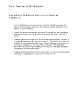
Truck Air Compressor Governor Adjustment .........................................................2-1
Pressure Protection Valve Adjustment ..................................................................2-3
Viewer Program Installation .................................................................................2-4
Pressure Setting File Loading ...............................................................................2-4
TROUBLE SHOOTING SECTION 3
Warnings ...............................................................................................................3-1
Alerts ....................................................................................................................3-2
Heater Current Error ............................................................................................3-4
OCU “HEATER INFO” Screen .............................................................................3-8
Valve No Power Alert ...........................................................................................3-9
Slight Air Leak Through Exhaust Port ................................................................3-13
“TRANS RANGE ERROR” Alert.........................................................................3-15
MAINTENANCE PROCEDURES SECTION 4
System Maintenance Overview ............................................................................4-1
Rotary Union Maintenance ...................................................................................4-2
Air Flow Check Procedures...................................................................................4-3
‘TIRE PRESSURE LOSS WARNING’ Check Procedures ...................................4-4
Static Tank Orifi ce Testing ....................................................................................4-5
Testing Overspeed Function ................................................................................4-6
Drive Axle Hanger Bracket and Hose Maintenance .............................................4-7
Tire Changing Procedures ...................................................................................4-9
Service Inspection Check Lists ................................................................................I
VALVE REBUILD PROCEDURES SECTION 5
f:tec\manuals\Service\SERVICEv5.indd - V6-0615
This Service Manual has been developed for typical North American designed vehicles. Electrical and air supply systems for
European vehicles may require different settings and procedures to work properly with those vehicles. The TIREBOSS
TM
operational procedures are similar for all vehicle types. For further information contact TPC International or a local TIREBOSS
TM
technical representative.
TIREBOSS
Tire Pressure Control
TM

i
SERVICE MANUAL
f:tec\manuals\Service\SERVICEv5.indd - V6-0615
TIREBOSS
TM
Tire Pressure Control
SYSTEM DESCRIPTION
The TIREBOSS
TM
Tire Pressure Control system consists of a computerized Operator Control Unit
(OCU), mounted in the cab, which monitors system activity and displays clear text messages to
the operator of the vehicle. The OCU is linked to a computerized Valve Control Module (VCM) and
pneumatic control valves located outside of the cab. The operator makes simple selections at the
OCU, based on load and speed, which in turn sends messages to the VCM allowing the control
valves to infl ate or defl ate the tire pressures within strict parameters set by the OCU.
The control valves are connected to the tire groups, and individual tire valve stems, through air
lines and various types of rotary couplings mounted at the wheel ends. The air is transferred into
(or out of) the tires through this hardware while the vehicle is moving (See “SYSTEM OVERVIEW”).
The control valves are supplied with air pressure from the vehicle’s air brake system. The air brake
system always has priority over the tire pressure system and is protected by two safety systems.
First a pneumatic pressure protection valve closes air supply to the tire pressure system if brake
tank pressure falls below 95 PSI. An electronic pressure switch that opens the electronic circuit if
the brake tank pressure drops to 75 PSI backs this up. This switch also activates an alert (“LOW
AIR SUPPLY”) on the OCU and electronically prevents any infl ation or defl ation of the tire pressure
system. The system will resume operation once air pressure builds above the safe limits.
Tire pressures are controlled to specifi c set points dependent on vehicle load and speed. Typical
tire pressures change from a maximum of 110 PSI, when fully loaded at highway speeds, down to
27 PSI when empty at reduced off-highway speeds. These pressure ranges are typical for truck
transport vehicles that operate with a standard air supply system and adhere to guidelines set by
the tire manufacturer for automotive applications.
The upper & lower limits for air pressure control are 150 PSI and 10 PSI respectively and are based
on the air supply capacity, pressure transducer limits and application. The control valves can ac-
commodate up to 75 CFM. Tire pressure control & display is accurate within a nominal range of
+/- 2 psi of actual tire pressure. The upper tolerance allows for normal heat buildup in the tires.
All of the operating tolerances are adjustable within the programming software.
The system has various built-in safety features to warn the driver of such things as over-speed
conditions or tire failures. Warnings are both visual and audible (See “SAFETY FEATURES”).

ii
SERVICE MANUAL
f:tec\manuals\Service\SERVICEv5.indd - V6-0615
TIREBOSS
TM
Tire Pressure Control
SAFETY FEATURES
The TIREBOSS
TM
Tire Pressure Control system (TPCS) incorporates a number of extremely important safety
features to ensure the integrity of the vehicle, tires and the safety of everyone on the highways. These include
features dealing with the following aspects of operation.
1. VEHICLE OVERSPEED CONDITION
If the vehicle’s speed exceeds the set point for the current selected tire pressure, the OVERSPEED CONDITION alert
screen will be displayed and an audible alarm will sound alerting the operator of a vehicle OVERSPEED CONDITION.
If the vehicle OVERSPEED CONDITION persists for a specifi ed period, typically 1 minute (This period is adjustable),
the system will automatically increase the selected pressure setting upward to the next higher tire pressure for the
selected load.
2. LOW AIR BRAKE SUPPLY PRESSURE
A pressure protection valve and an electronic safety switch make sure that air is available for tire infl ations only when
vehicle system air brake pressure is above a safe level (95 psi). If the air brake pressure falls below a safe level, the
LOW AIR SUPPLY alert will be displayed and the air supply is shut off to the TPCS. The supply of compressed air to
the vehicle air brake system always has priority over the TPCS.
3. LOSS OF TIRE PRESSURE
When an unexplained drop in tire pressure takes place in any of the zones, an audible alarm will sound. The tire pres-
sure status display on the operator control unit will fl ash the zone display in which the loss of tire pressure has occurred
and it will alternate with the TIRE PRESSURE LOSS alert. The source of the pressure drop must be located prior to
continuing operation so that appropriate action may be taken, such as isolating the problem tire from the rest of those
in the zone, through the use of manual shutoff valves.
4. AIR FLOW RESTRICTION
The TIREBOSS
TM
system is designed to work normally with all wheel valves open maintaining constant monitoring &
control of tire pressures. If the valves are left in a closed position, the system only senses line pressure and begins
infl ating & defl ating past the set point pressure. This repetitive action will cause the AIR FLOW RESTRICTION ALERT
to be activated. This alert will continue until the valves are re-opened allowing normal operation to resume.
5. TIRE OVER-PRESSURE
The TIREBOSS
TM
system automatically assigns upper and lower limits to the programmable set points. The system
will trim the tire pressures for a preset time, after a new selection is made, to hone in on the new setting. Following the
initial “trimming” time, the tire pressures are allowed to increase above the trim tolerance to allow for normal heat build
up. If the tire pressure exceeds a maximum limit, the TIRE OVER-PRESSURE ALERT will be displayed indicating an
overheat condition in the tire which may be caused from improper pressure settings or a failure of other vehicle compo-
nents, such as the brakes overheating.
6. LOAD SENSING FEATURE (Applicable to air suspension vehicles only)
Vehicles equipped with air suspension on the drive axles can be fi tted with a load sensing option. A load sensing
pressure switch indicates to the control system when the vehicle is loaded and will not allow any of the unloaded set-
tings to be selected. This feature limits the selections to the driver and ensures only the appropriate tire pressures
are being used for current vehicle load.
In addition to the system safety features outlined above, it should be noted that the TIREBOSS
TM
systems
use only quality components, such as DOT approved drive axle air hosing. The TPCS computer continu-
ously monitors tire pressure and controls the infl ating, defl ating, or maintaining of a preselected target tire
pressure. The systems carry operational decaling, which is further explained in an operator’s manual carried
in each vehicle.

TIREBOSS
TM
Tire Pressure Control
SERVICE MANUAL
SECTION 1
SYSTEM SCHEMATICS
AND DIAGRAMS

1-1
TIREBOSS
TM
Tire Pressure Control
SERVICE MANUAL
f:tec\manuals\Service\SERVICEv5.indd - V6-0615
SYSTEM OVERVIEW
Valve Box
Drive Axle Main Line
Y-Fitting
TRUCK
CAB
Operator
Control Unit
Drive Axle
Hose Hangers
Truck Wet Tank
Pressure
Protection Valve
Drive Axle
Hoses
Brake Pressure
Protection Switch
Air Line
TPCS
Air Supply Line
Operator
Control Cable
Speed/Ignition
Cable
Wheel End
Manifold Assembly
Steer Axle
Main Line
(optional)
Steer Shut-off Valves
(located on frame)

1-2
TIREBOSS
TM
Tire Pressure Control
SERVICE MANUAL
f:tec\manuals\Service\SERVICEv5.indd - V6-0615
TIREBOSS
AIR and ELECTRICAL
SCHEMATIC
Primary
Tank
Secondary
Tank
pneumatic control lines
main air supply lines
electronic signal lines
RES
UNL
Truck
Compressor
Air Drying
System
TIREBOSS
Valve Box
(At truck frame)
Truck Wet Tank
Brake Pressure
Protection Switch
Air Line
Pressure
Protection
Valve
Standpipe
Compressor Governor Sensing Line
Air Supply
to Tires
Compressor
Governor
OPERATOR
CONTROL UNIT
Truck Battery
(12 V / 24 V)
Remote Alarm Cable
(optional)
TIREBOSS Main Air Supply
The ‘switching out’ of OCUs between
trucks is not recommended as
settings and speed functions have
to be adjusted per truck
specifi cations.

NOTE: If vehicle is equipped with only one D2 governor then
the compressor sensing line must be located at the truck wet
tank and the dryers unloader line located at the unloader
port of the compressor D2 governor.
PLUMBING SCHEMATIC
-TRUCK WITH
RECEIVER TANK-
DRYER GOVERNOR SENSING
LINE TO TRUCK WET TANK
1/4 AIRBRAKE TUBE
TRUCK
WET TANK
Internal Standpipe
- mounted inside wet tank
5/8 AIRBRAKE TUBE SUPPLY LINE
Pressure Protection Valve
(Internal Relief Valve)
Adjusted to 100 psi
T
U
RBO-20
0
0
UNLOADER LINE
TO
TIREBOSS
VALVE BOX
PURGE
TANK
PURGE
TANK
UNLOADER LINE
DRYER GOVERNOR
-unload at 125 psi
TRUCK
COMPRESSOR
COMPRESSOR GOVERNOR
-unload at 135 psi
HEATER
250 psi
Safety Relief Valve
One Way
Check Valve
Air Drying
System
-12 TEFLON
with 16.5 cfm
compressor
-16 TEFLON
with 30 cfm
compressor
FACTORY
RECEIVER
TANK
NOTE: Compressor Governor must
be adjusted to 135 psi fi rst, then
adjust Dryer Governor to 125 psi.
(See “Truck Air Compressor Gover-
nor Adjustment” in
Service Manual for details)
5/8 AIRBRAKE TUBE
Install Temporary Gauge
Here to set Dryer Governor
to 125psi
100
Install Temporary
Inline Gauge Here to set
Compressor Governor to
135psi
100
TIREBOSS
TM
Tire Pressure Control
SERVICE MANUAL
1-3
f:tec\manuals\Service\SERVICEv5.indd - V6-0615

1-4
TIREBOSS
TM
Tire Pressure Control
SERVICE MANUAL
f:tec\manuals\Service\SERVICEv5.indd - V6-0615
TIREBOSS
TM
AIR and ELECTRICAL SCHEMATIC WITH
(BENDIX) AD-IS DRYER
TIREBOSS
Valve Box
(At truck frame)
Air Supply
to Tires
OPERATOR
CONTROL UNIT
Truck Battery
(12 V / 24 V)
pneumatic control lines
main air supply lines
electronic signal lines
TIREBOSS Main Air Supply
Remote Alarm
Cable (optional)
Factory
Pressure
Relief Valve
Air Governor
AD-IS
Air Drying
System
UNL
Truck
Compressor
Brake
Pressure
Protection
Switch Air
Line
Primary
Tank
Secondary
Tank
3/8” Air Tube
Dryer Body
3/8” Push to Lock
The ‘switching out’ of
OCUs between trucks is
not recommended as
settings and speed
functions have to be
adjusted per truck
specifi cations.
Optional Wet
Tank
Pressure Protection Valve
(Internal Relief Valve)
Adjusted to 100 psi
NOTE: Pressure Protection Valve
can be mounted at optional wet tank
or at TIREBOSS Valve Box

TIREBOSS
TM
Tire Pressure Control
SERVICE MANUAL
1-5
f:tec\manuals\Service\SERVICEv5.indd - V6-0615
TIREBOSS
TM
WIRING DIAGRAM
OPERATOR CONTROL CABLE
VALVE PACK BOX
Air Ports
to tires
POWER/DATA
SPEED/IGNITION
COMM A
COMM B
DATA LOGGER IN-
TERFACE PORT
PROGRAM PORT
OPERATOR
CONTROL UNIT
(Cab Mounted)
SPEED SIGNAL
(From Data Link, Impulse
Sender, Frequency Gen-
erator or
Frequency Convertor)
DATA STREAM BUS - (Data Link input)
DATA STREAM BUS
+ (Data Link input)
+12/24V IGNITION SWITCHED ON
(Not Accessory)
12/24V IGNITION SOURCE
Remote Alarm Cable (optional)
Remote Alarm
(optional)
+
-
Ground Connection
GREEN
BLACK
FUSED RED
The ‘switching out’ of
OCUs between trucks is
not recommended as
settings and speed
functions have to be
adjusted per truck
specifi cations.
Fuse holder with
15 amp fuse
White Wire
(Positive)
Black Wire
(Ground)
NOTE - Black Wire to neg.
battery post unless truck has
a Power Disconnect Switch on
ground circuit. Then Black Wire
must be connected to switched
side of master switch.
(24 volt)
(12 volt)
-
+
Truck
Battery
(12 volt)
-
+
Truck
Battery
(12 volt)
(Use 24 volt only if
circuit board, heaters
and controller have
been set for 24 volt
use)
NOTE - White Wire to pos.
battery post unless truck has
a Power Disconnect Switch
on positive circuit. Then White
Wire must be connected
to switched side of master
switch.
G - GPS
J - Data Bus
P - Pulse
Black & Green wires are not
connected on GPS equipped
TIREBOSS systems.
Marked G on rear panel

1-6
f:tec\manuals\Service\SERVICEv5.indd - V6-0615
OPERATOR CONTROL CIRCUIT BOARD
SERVICE MANUAL
TIREBOSS
TM
Tire Pressure Control
BACK OF
CAB CONTROLLER
J1
J2
J5
J6
J8
ELTEK 1483-00
SPEED BOARD
OPERATOR CONTROL
CIRCUIT BOARD
654321
Speed Board Mount
Stand Off Posts
Sonalert
Header
Programming
Header
Datalogger
Header
Power/Data
Header
Power ON/
OFF Header
J4
Speed Board
Header
Speed/Ignition
Header
SPEED BOARD POSITION LABEL (J or P)

1-7
TIREBOSS
TM
Tire Pressure Control
SERVICE MANUAL
f:tec\manuals\Service\SERVICEv5.indd - V6-0615
VALVE CIRCUIT BOARD #1393-01
BLUE
PURPLE
VALVE
BODY
HEATER
FUSE
-10-
ELTEK 1393-01
3CR
CONTROL
RELAY
HT-1
HT-2
J 2
TH-1
TH-2
F2
J 7
WHITE
BRAKE PRESSURE
PROTECTION SWITCH

TIREBOSS
TM
Tire Pressure Control
SERVICE MANUAL
1-8
f:tec\manuals\Service\SERVICEv5.indd - V6-0615
RED
GREEN
BLACK
WHITE
RED
GREEN
BLACK
WHITE
RED
GREEN
BLACK
WHITE
AXLE 1
INFLATE
SOLENOID
AXLE 1
DEFLATE
SOLENOID
AXLE 2
INFLATE
SOLENOID
AXLE 2
DEFLATE
SOLENOID
AXLE 3
INFLATE
SOLENOID
AXLE 3
DEFLATE
SOLENOID
EXTERNAL
REMOTE ALARM
(IF EQUIPPED)
+
-
12v / 24v VDC REMOTE
ALARM POSITIVE SUPPLY
PURPLE
BLUE
SUSPENSION
PRESSURE SWITCH
(NORMALLY CLOSED)
WHITE
BLACK
BLACK
BLACK
ORANGE
BROWN
BLUE
RED
GREEN
VALVE BODY HEATER
CONTROL (THERMISTOR)
(IF EQUIPPED)
ORANGE
BLUE
GREEN
BLACK
RED
BROWN
OCU
POWER/DATA
CABLE
CONNECTOR
POWER DATA CABLE
(NOTE: WHITE NOT USED)
24V HEATER SUPPLY
12V HEATER SUPPLY
INF. DEF.
AXLE GROUP 1
INF. DEF.
AXLE GROUP 2
INF. DEF.
AXLE GROUP 3
PS1-A
PS1-B
PS2-A
PS2-B
ALRM
ALRM
TH1
TH2
-DATA
+DATA
+12V
VPS
-VBAT
RLY
HT COM
HT-28v
HT-14v
- 10 -
+VBAT-VBAT
AXLE 1
AXLE 2
AXLE 3
J7
VALVE CONTROL
MODULE CIRCUIT
BOARD
White Wire (Positive)
Black Wire (Ground)
12/24v
Jumper
(blue)
24v 12v
DO NOT INSTALL MOUNT
SCREWS INTO THESE TWO
HOLES AS THEY WILL
SHORT CIRCUIT BOARD!
ELTEK 1393-02
VALVE CIRCUIT BOARD #1393-02
Valve
Body
Heater
Fuse
VALVE BODY
HEATERS
(IF EQUIPPED)
WHITE
Steer
Drive
Trailer
RED
F2
J2
3CR
Control
Relay
J3
F4
F8
F6
F7
F5
F9
1CR
NOTE - Black Wire
to neg. battery post
unless truck has a
Power Disconnect
Switch. Then Black
Wire must be con-
nected to truck frame.
15 amp
Fuse
(12 volt)
(24 volt)
-
Truck
Battery
(12 volt)
-
+
Truck
Battery
(12 volt)
+
(Use 24 volt only if circuit board,
heaters and controller have been
set for 24 volt use)
L1 L2 L3 L4 L9L5 L6 L7 L8 L10
BRAKE PRESSURE
PROTECTION SWITCH
(NORMALLY OPEN)
NOTE - White Wire to pos. battery
post unless truck has a Power
Disconnect Switch on positive
circuit. Then White Wire must
be connected to switched side of
master switch.

SERVICE MANUAL
TIREBOSS
TM
Tire Pressure Control
1-9
f:tec\manuals\Service\SERVICEv5.indd - V6-0615
VALVE CIRCUIT BOARD (#1393-02)
INDICATOR LIGHT DESCRIPTIONS
12v / 24v VDC REMOTE
ALARM POSITIVE SUPPLY
INF. DEF.
AXLE GROUP 1
INF. DEF.
AXLE GROUP 2
INF. DEF.
AXLE GROUP 3
- 10 -
+VBAT-VBAT
AXLE 1
AXLE 2
AXLE 3
J7
VALVE CONTROL
MODULE CIRCUIT
BOARD
12/24v
Jumper
(blue)
24v 12v
ELTEK 1393-02
Valve
Body
Heater
Fuse
Steer
Drive
Trailer
RED
F2
J2
3CR
Control
Relay
J3
F4
F8
F6
F7
F5
F9
1CR
The LED indicator lights on the valve circuit board may assist in trouble shooting and/or diagnosing of the electronic circuits.
When the TIREBOSS system is operating and communicating correctly, the LED indicator lights will illuminate as follows...
*Key OFF - LED L2 and LED L4 illuminated solid green (with main power available at +V Bat)
*Key ON - All LED’s illuminated solid green and LED L3 fl ashing RED
*(If equipped, POWER DISCONNECT SWITCH must be ON)
If an LED light illuminates dim, fl ickers or does not come on as described above,
a fault with that electronic circuit may be present.
The diagram below indicates the electronic circuit for each LED.
In the event of a faulty circuit, a fault may
exist in the following areas...
-low battery power supply
-replaceable fuses (heater, battery or ignition fuse)
-poor terminal connection/s
-valve circuit board or OCU circuit board
-abraded wires
L1 L2 L3 L4 L9L5 L6 L7 L8 L10
Valve Control Module (+12V/+24V)
Cab Control Module Power Supply (F1)
Cab Control/Valve Control Communication Indicator
Valve Control Module +5V Power Supply (F3)
Valve Heater Supply (F2)
Brake Pressure Sw./Suspension System Pressure Sw. Supply (F4)
Valve Solenoid Supply - Axle1 (F5)
Valve Solenoid Supply - Axle2 (F6)
Valve Solenoid Supply - Axle3 (F7)
Remote Alarm Relay (2CR) and Valve Heater Relay (3CR) Supply (F8)
GGRGG GGG G G
2CR
Control
Relay

1-10
f:tec\manuals\Service\SERVICEv5.indd - V6-0615
The internal TIREBOSS OCU connections are as follows:
Internal J5 header TIREBOSS DB9 SUB D
Pin 1 (TX) (White/Red wire) Pin 2
Pin 2 (RX) (White/Green wire) Pin 3
Pin 4 (Signal Common) (Black wire) Pin 5
SERVICE MANUAL
TIREBOSS
TM
Tire Pressure Control
WHITE
GREY
PURPLE
BLACK
BLUE
WHITE/GREEN
WHITE/RED
PIN 7
PIN 6
PIN 5
PIN 4
PIN 3
PIN 2
PIN 1
J5
J6
INTERNAL J5 HEADER
Data Logger Connections to TIREBOSS
The Data Logger port is located on the
back of the Operator Control Unit (OCU).
It is a standard DB9 Serial port male connector
and is labelled COM A or DATALOGGER
(has the molded female sockets).
The pin connectors are as follows:
TIREBOSS DB9 SUB D Connections
Pin 1 (no connect)
Pin 2 TX DATA
Pin 3 RX DATA
Pin 4 DTR (not used)
Pin 5 Signal Common (Ground)
Pin 6 DSR (not used)
Pin 7 CTS (not used)
Pin 8 RTS (not used)
Pin 9 (no connect)
POWER/DATA
SPEED/IGNITION
COMM A
COMM B
DATA LOGGER IN-
TERFACE PORT
DATA LOGGER
PROGRAMMING
BACK OF COMM A
(DB9 SUB D)
(view from inside cover)
PIN 5 Signal Common
(Ground)(black)
PIN 4 DTR (not used)(blue)
PIN 3 RX DATA(white/green)
PIN 2 TX DATA(white/red)
PIN 1 (no connect)
PIN 6 DSR (not used)(purple)
PIN 7 CTS (not used)(grey)
PIN 8 RTS (not used)(white)
PIN 9 (no connect)

Load Sense
Pressure
Switch
(if equipped)
1-11
f:tec\manuals\Service\SERVICEv5.indd - V6-0615
SERVICE MANUAL
TIREBOSS
TM
Tire Pressure Control
Drive Axle Valve Body
Valve Control Module (VCM)
Schrader Valve (Drive Axle)
Steer Axle Static Tank (if equipped)
M1396740
System
Serial
Number
M1396740
Steer or Trailer Axle Valve Body
Schrader Valve
(Steer or Trailer Axle, if equipped)
Schrader Valve
(Steer Axle, if equipped)
Steer Axle Valve Body
Drive Axle Static Tank
Trailer Axle Static Tank (if equipped)
D
S
T
D
S
T
Exhaust Port (closest fi tting
to front of valve box)
VALVE BOX
DIAGRAM
VCM Bracket
Orifi ce Fitting
Orifi ce Fitting
Orifi ce Fitting
Fittings to receive
air pressure from
Air Suspension
(if equipped)
Transducer
Fittings
Power/Communication Elec-
trical Cable Umbilical
Valve Solenoids
(see detail below)
THERMISTOR
(only mounted on the top valve)
(only on systems with valve heaters)
INFLATE SOLENOID
(with Red/Green Harness)
DEFLATE SOLENOID
(with White/Black Harness)
MANUAL LEVER
MANUAL LEVER
*front view of valve
Box
Vent
*view from bottom of box
Exhaust Port
3/8” Air Brake Tube
Air Supply Line from
Truck Wet Tank
Truck Frame
Brake Pressure
Protection Switch
Air Line & Fitting
Supply Inlet
Fittings to receive
air pressure from
Air Suspension
(if equipped)

1-12
f:tec\manuals\Service\SERVICEv5.indd - V6-0615
SERVICE MANUAL
TIREBOSS
TM
Tire Pressure Control
OPERATOR CONTROL UNIT (OCU)
BUTTONS AND SCREEN DESCRIPTIONS
STOP
DIM
CANCELMENUENTER
SELECT
TPC
INTERNATIONAL
ELTEK
R
TIREBOSS
TM
Tire Pressure Control
AXLE STATUS PSI
Steer INF 70
Drive DEF 40
Trailer O.K. 30
Will dim LED display and
white lettering on OCU will
illuminate
Will re-enable disabled
trailer circuit when held
for 2 seconds
Allows Operator to enter MENU options..
-push menu once and Application screen
will appear (push ENTER for different
Application Screens)
Will allow Operator to..
- cancel an alert
- exit a menu option screen
Will allow Operator to..
- enter/apply settings
- enter/apply applications
- enter/apply menu options
Shows axle group being
controlled. (If steer or trailer
is not TIREBOSS equipped,
that axle group, status and
pressure will not appear)
Displays each axle group status
INF - Infl ation cycle active
DEF - Defl ation cycle active
O.K. - within programmed pressure tolerances
****
- trailer axles only disabled
BLANK - A warning has appeared and
function has been suspended
Displays actual axle group
pressure/s (can be
displayed in PSI or KPA)
Will allow
Operator to..
- scroll up
through se-
lections
Will allow Op-
erator to..
- scroll down
through selec-
tions
TRAILER CIRCUIT OVERRIDE FUNCTION
This function is used only when pulling a trailer that is not equipped with
TIREBOSS Tire Pressure Control or when not pulling a trailer.
Non-equipped or non-connected trailers will cause the TRAILER “AIR FLOW RESTRICTION” alert to activate.
Push & Hold the ‘CANCEL’ button for 2 seconds until a single beep is heard.
The alert stops & the trailer circuit will be de-activated (trailer STATUS fl ashes ****).
To resume normal operation, Push & Hold the ‘STOP’ button for 2 seconds.

SERVICE MANUAL
TIREBOSS
TM
Tire Pressure Control
OPERATOR CONTROL UNIT (OCU)
SELECTION SEQUENCES
The following information and selection screens can be accessed by using the
following selection sequences....
1-13
f:tec\manuals\Service\SERVICEv5.indd - V6-0615
TO ACCESS...
PUSH...
DETAILS...
NOTE...
SPEED FREQ.
SET-UP
MENU
ENTER
DOWN
...will display number of hertz being
sensed by system
...should read 0 Hz when vehicle is
stationary
CAB SET-UP
FILE
MENU
ENTER
DOWN
...will display customer/system se-
rial number
(ie. M-tboss00000.ca)
...screen will return to normal view
after 30 seconds
CAB PROGRAM
VERSION
MENU
ENTER
DOWN
...will display cab fi rmware program
version number (ie. CabV301)
...screen will return to normal view
after 30 seconds
DOWN
DOWN DOWN
APPLICATION
MENU
ENTER
...will display Application Name and
Number currently in use
CHANGING
APPLICATION
MENU
ENTER
...will change application number
...pushing up or down will scroll
through applications. Stop on
desired application and push and
hold ENTER.
DOWN
or
... always keep current Application
Pressure Setting Cab Card in front in
sleeve for easy operator reference
ENTER
UP
CHANGING
SETTING within
an APPLICATION
...will change Setting number
within an application
DOWN
or
...pushing up or down once will indi-
cate current setting and pushing up or
down more than once will scroll set-
ting. Stop on desired setting. System
will change automatically in
5 seconds or push ENTER for immedi-
ate activation
UP
ENTER
VALVE
PROGRAM
VERSION
MENU
DOWN
...will display valve fi rmware pro-
gram version number
(ie. ValV202)
...screen will return to normal view
after 30 seconds
TPC SYSTEM
SERIAL NUM-
BER
MENU
ENTER
DOWN
...will display TPC Serial Number of
Valve Box (ie. MigBCA00J0000)
...screen will return to normal view
after 30 seconds
...this number MUST match the serial
number inside the valve box on VCM
bracket.
TIREBOSS
VERSION
MENU
ENTER
DOWN
...will display software version num-
ber (ie. 2.0.8.1 405)
...screen will return to normal view
after 30 seconds
six times
fi ve times
ENTER
four times
HEATER INFO
**(not available
with all software
versions)
MENU
ENTER
DOWN
...used to display heater Volts and
Watts
... used for testing heaters
...screen will return to normal view
after 30 seconds
...refer to OCU “Heater Info” Screen in
this manual for more details
seven times
PROGRAM
MODE
MENU
ENTER
DOWN
...used to program Operator Control
Unit
...done by factory authorized personal
only.
eight times
PROGRAM
MODE
**(versions with-
out ‘heater info
screen’)
MENU
ENTER
DOWN
seven times
...used to program Operator Control
Unit
...done by factory authorized personal
only.

SERVICE MANUAL
TIREBOSS
TM
Tire Pressure Control
OPERATOR GUIDE AND
PRESSURE SETTING CAB CARDS
Supplied with each system at time of install is an Operator Guide and a set of Pressure
Setting Cab cards. Pressure Setting Cab Cards are specifi c to each truck and
application. Operator Guide and Pressure Setting Cab cards must remain with the TIRE-
BOSS equipped vehicle at all times.
1-14
f:tec\manuals\Service\SERVICEv5.indd - V6-0615
Page one gives a quick
outline of the
Operator Control Unit
push-button functions
for the operator.
Page two and three outlines the operation features to
be used by the driver during a haul cycle as well as
the three most important safety features.
Page four has a clear plastic sleeve which contains the Pressure Setting Cab Cards for that
particular unit. They show the specifi c pressure, speed settings and maximum allowable times
for each application setting. A system may have as many as eight Application Cards.
100
90
60
70
95
100
50
90
APP-1
SUMMER HAUL 1
TIREBOSS
COMPANY NAME
APPLICATION
NUMBER
APPLICATION
NAME
NOTE... always keep
current Application Pres-
sure Setting Cab Card in
front of sleeve for easy
operator reference

TIREBOSS
TM
Tire Pressure Control
SERVICE MANUAL
SECTION 2
ADJUSTMENTS
AND SETTINGS
/