Proscend 850G-12PI Installation guide

Type
Installation guide

Proscend 850G-12PI is an Industrial Ethernet Switch designed for harsh environments, offering reliable connectivity for industrial automation, security surveillance, and other demanding applications. It features 12 Fast Ethernet ports, 2 SFP uplink ports, PoE capability, and robust protection against electromagnetic interference (EMI) and electrostatic discharge (ESD). With its compact and rugged design, the 850G-12PI is ideal for space-constrained installations and ensures stable operation in extreme temperatures.

Proscend 850G-12PI is an Industrial Ethernet Switch designed for harsh environments, offering reliable connectivity for industrial automation, security surveillance, and other demanding applications. It features 12 Fast Ethernet ports, 2 SFP uplink ports, PoE capability, and robust protection against electromagnetic interference (EMI) and electrostatic discharge (ESD). With its compact and rugged design, the 850G-12PI is ideal for space-constrained installations and ensures stable operation in extreme temperatures.

- 1 -
850G-12PI, 850G-14I, 850G-12I
Industrial Ethernet Switches
Quick Installation Guide
The 850G Series Industrial Ethernet Switch can be powered from two
power supplies (input range 12 ~ 58 VDC for non-PoE Series, 54 ~ 58 VDC
for PoE Series). Two power supplies are on the top panel of the switch.
Insert the positive and negative wires (AWG 14-26) into V+ and V- contacts
on the terminal block respectively and tighten the wire-clamp screws to
prevent the wires from being loosened.
Non-PoE Series
PoE Series
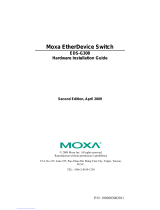
The pin assignment of RJ45 connector is shown in the following table.
8-pin RJ45
The DC power should be connected to a well-fused power supply.
The alarm relay output contacts are in the middle of the DC terminal
block connector as shown in the figure below.
The alarm relay out is “Normal Open”, and it will be closed when it is
detecting any predefined failure such as power failures or Ethernet link
failures.
The relay output with current carrying capacity of 0.5A @ 24 VDC.
The switch must be properly grounded for optimum system performance.
The console port on the top panel is for local management by using a
terminal emulator or a computer with terminal emulation software.
DB9 connector connect to computer COM port
Baud rate: 115200bps
8 data bits, 1 stop bit
None Priority
None flow control
To connect the host PC to the console port, a RJ45 (male)
connector-to-RS232 DB9 (female) connector cable is used (not included in
package). The RJ45 connector of the cable is connected to the console port
of the switch; the DB9 connector of the cable is connected to the PC COM
port. The pin assignment of the console cable is shown below:
WARNING
1
6
2
RD
7
3
TD
8
4
9
5
DGND
8
7
6 (DGND)
5
4 (TD)
3 (RD)
2
1
Alarm system
External Power system
Ground Connector
First Power Supply
LED Indicators
RJ45 Connector Pinouts
Version: 1.10
LED
Color
Description
P1/P2
On: Green
P1/P2 power line connected or power supplied
Off
P1/P2 power line disconnected or no power supplied
ALM (Alarm)
On: Red
Ethernet link failure or power failure
Off
No Ethernet link failure and no power failure
RJ45 LAN port
Link/Act
On: Green
Ethernet LINK UP
Blinking: Green
Ethernet traffic detected
Off
Ethernet LINK DOWN
RJ45 LAN port
Speed
On: Yellow
Ethernet LINK UP at 1000Mbps
Off
Ethernet LINK DOWN or LINK UP at 10Mbps/100Mbps
SFP Uplink port
Link/Act
On: Green
Ethernet LINK UP
Off
Ethernet LINK DOWN
SFP Uplink port
Speed
On: Yellow
Ethernet LINK UP at 1000Mbps
Off
Ethernet LINK DOWN or LINK UP at 100Mbps
PoE Series only
Ring Master
On: Green
Ring Master enabled
Off
Ring Slave enabled
Ring Fail
On: Green
Ring failure detected
Off
No Ring failure detected
PoE
On: Yellow
PoE PD (Powered Device) connected
Off
PoE PD (Powered Device) disconnected
Pin
Description
PoE Pinouts (PoE models only)
1,2
T/Rx+,T/Rx-
V+
3,6
T/Rx+,T/Rx-
V-
4,5
T/Rx+,T/Rx-
X
7,8
T/Rx+,T/Rx-
X
Connecting Power
First Power Supply
Second Power Supply
1
8
Console Connection
Alarm Relay and Ground
- 2 -
STEP 1: Use the screws to install the DIN-rail kit to attach at the rear side
of the switch.
STEP 2: Hook the unit onto the DIN-rail.
STEP 3: Push the bottom of the unit towards the DIN-rail until it locks in
place.
NOTE: For all switches (Non-PoE Series, PoE Series), the operation of DIN-rail mounting is the
same.
1. Key-in the command under Telnet: telnet 192.0.2.1
2. Login with default account and password.
Username: admin
Password: (none)
3. Change the IP with commands listed below:
Please scan below QR Code to download online resources.
Download Link:
https://www.proscend.com/en/product/850G-12PI.html
https://www.proscend.com/en/product/850G-14I.html
https://www.proscend.com/en/product/850G-12I.html
850G-12PI 850G-14I 850G-12I
Use the screws to install the wall-mounting kit to attach at the rear side of
the switch.
NOTE: For all switches (Non-PoE Series, PoE Series), the operation of wall mounting is the same.
1. Factory default IP: 192.0.2.1
2. Login with default account and password.
Username: admin
Password: (none)
P/N: 604040000065
DIN-rail Mounting
CLI Initialization and Configuration
Wall Mounting
M4 Screw
172.0
enable
configure terminal
interface vlan 1
ip address xxx.xxx.xxx.xxx xxx.xxx.xxx.xxx
exit
NOTE
Web Interface: Connect & Login
  • Page 1 1
  • Page 2 2

Proscend 850G-12PI Installation guide

Type
Installation guide

Proscend 850G-12PI is an Industrial Ethernet Switch designed for harsh environments, offering reliable connectivity for industrial automation, security surveillance, and other demanding applications. It features 12 Fast Ethernet ports, 2 SFP uplink ports, PoE capability, and robust protection against electromagnetic interference (EMI) and electrostatic discharge (ESD). With its compact and rugged design, the 850G-12PI is ideal for space-constrained installations and ensures stable operation in extreme temperatures.

Ask a question and I''ll find the answer in the document

Finding information in a document is now easier with AI