Page is loading ...

00
What is Arduino
Project 0
www.dfrobot.com
SAMPLE CODE CLICK HERE>> https://bit.ly/2DxKjLO

What is Arduino?
Arduino is an open-source electronics prototyping platform based on flexible, easy-to-use hardware and
software. It is intended for artists, designers, hobbyists and anyone interested in creating interactive objects
or developing environments.
Arduino can sense its environment by receiving inputs from sensors, and interact with its environment by controlling
lights, motors, or other actuators. The Arduino integrated development environment (IDE) is a cross-platform
application written in Java, and is derived from the IDE for the Processing programming language and wiring
projects. It can run independently and communicate with other software such as Flash, Processing, MaxMSP
and more. Arduino IDE is open source so you can download and share thousands of interactive projects for
free!
// make sound notification when coffee is done
// email notification via mobile
// blinking fluffy toy
// Professor X’s steam punk wheel chair with voice recognition and drink serving function
// a Star War arm gun
// a pulse monitor to store data when biking
// a robot that can run in snow and draw pictures on the floor
Here are some Arduino projects just to give your some ideas of tasks it can complete.
www.dfrobot.com
01
00. What is Arduino

History
Arduino UNO
Arduino started in 2005 as a project for students at the Interaction Design Institute Ivrea in Ivrea, Italy. At that
time, programming students used a "BASIC Stamp" for projects. This was at a cost of $100, considered expensive
for students.
Massimo Banzi, one of the founders of Arduino, taught at Ivrea. The name "Arduino" comes from a bar in Ivrea
where some of the founders of the project used to meet. The bar itself was named after Arduino, Margrave of
Ivrea and King of Italy from 1002 to 1014.
Colombian student Hernando Barragan contributed a hardware thesis for a wiring design. After the wiring
platform was complete, researchers worked to make it lighter, less expensive, and available to the open source
community. The school eventually closed down, so these researchers, including a man called David Cuartielles,
promoted the idea. This idea was to become the Arduino as we know it today.
Now let’s take a close look at the Arduino micro-controller and try to locate I/O ports (input/output) and on
board LEDs.
www.dfrobot.com
◆ I/ O pins, digital pins 0-13, analog pins 0-5.
◆ 2 power sources. One is the USB port that can draw power from the USB connection. Another is power jack that
inputs DC power of 6-12 volts.
◆ 4 LEDs and reset button. L is the on board LED that connects with digital pin 13. TX and RX are indicators of
transmission signal and received signal. When we download a sketch to the Arduino, these two lights blink,
indicating that data is being transmitted and received.
02
00. What is Arduino
Digital Pins 0~13
(PWM Pins 3,5,6,9,10,11)
Power
Indicator
Analog Pin 0~5
3.3V Output
DC Power Jack
(6~12V)
Port Communication
Indicator
D13 Pin Signal
Indicator
USB Port
Reset
5V Output

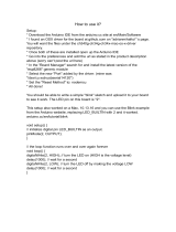
First Use
1. Download Arduino IDE
Go to
http://arduino.cc/en/Main/Software
to download the installation file
according to your operation system.
For Windows users, please follow
the instructions below. For Mac
and Linux users, you can directly use
the Arduino sketch by simply
clicking on the file.
www.dfrobot.com
03
00. What is Arduino

2. Install the drivers
Installing drivers for the Arduino
Plug in your board and wait for
Windows to begin its driver
installation process. After a few
moments, despite its best ef-
forts, the process will fail, but
do not panic! Click on the Start
Menu, and open up the Control
Panel.
Find
nnnUUU kkk ooonnn www nnn DDD vvveee iii eeeccc and then
right click and select
UUU eeetttaaadddppp
DDD rrreeevvviiirrr SSSoooffftttwww eeerrraaa
.
www.dfrobot.com
04
00. What is Arduino

Choose ooorrr www mmmoooccc yyymmm eeesss rrreeetttuuu fff rrrooo
ooosss rrreeevvviiirrrddd ffftttwww eeerrraaa
to search for dri-
vers manua
y
Click eeessswwwooorrrBBB and find the
director
location of the Arduino
IDE
where the installation files
are located
. Inside this director
will be another director named
sssrrreeevvviiirrrDDD . elect it and click tttxxxeeeNNN .
www.dfrobot.com
05
00. What is Arduino

This dialog indicates successful
installation. Hopefull
this is what
ou will see! f not double check
our steps and tr again.
If you go back to your device
manager, the Arduino device
should now be recognised by your
computer.
Go to “ eeeccciiivvveeeDDD rrreeegggaaannnaaaMMM ” >“ tttrrroooPPP sss
MMMOOOCCC((( &&& )))TTTPPPLLL ”. You should see
“ ooonnniiiuuudddrrrAAA
MMMOOOCCC((( ooonnn ###)))”. This is the
COM port that your computer uses
to transfer data to your Arduino. In
our example the computer com-
municates with the Arduino on
COM36.
Remember your COM number as
you will need it later.
www.dfrobot.com
06
00. What is Arduino

07
00. What is Arduinowww.dfrobot.com
4. Upload a Blink program
Open Arduino IDE and take a moment to move your mouse along each icon to get to know their functions.
Here we will use a very basic sample code,
BBB kkknnniiilll to go through the whole process and test whether the
controller is working.
Open the LED blink example sketch. You will find it under
>>> ssseeelllpppmmmaaaxxxEEE >>> eeellliiiFFF 000 kkknnniiilllBBB >>> sssccciiisssaaaBBB...111 .
07
00. What is Arduino

www.dfrobot.com
“VVVeee ” from
instructions that the computer can understand.
d mmm iiillliiippp nnnggg...
08
00. What is Arduino

The code we are using should not have errors since it is an example
code. If a code does have errors in it
it will fail to verify.
Time to download the code to your Arduino! Select your micro
troller by sele ting “ ”.
Then sele
t your C M port by sele ting “ eeeSSS aaaiiirrr lll PPP rrrooo ttt” and sele ting the
C M
port number you saw earlier.
In our example C M36 is in use.
www.dfrobot.com
09
00. What is Arduino

10
www.dfrobot.com 00. What is Arduino
C “ pload”
Arduino.
After it is finished, the Arduino will run the code automatically and
the onboard LED will start to blink, just as programmed!
RRReeevvv wwweeeiii
In order to upload
od must do the following steps:
dddoooCCC eee eeesssoooooohhhCCC >>> BBB dddrrraaaooo dddnnnaaa PPP tttrrrooo >>>
...

01
Project 1
LED Flashing
www.dfrobot.com.cn

01
www.dfrobot.com
01. LED Flashing
Let's get started!
Let’s kickstart our Arduino adventure! In the first lesson, you will learn
the basics of components such as LEDs, buttons and resistors - includ-
ing pull-up and pull-down resistors. Additionally, you will start to write
Arduino sketches to control a LED with your Arduino.

02
www.dfrobot.com
01. LED Flashing
LED Flashing
In use the Blink on- .
T
can have a clear idea of how a LED works and how they can be used in a circuit.
*You may need to choose a different value resistor depending on the
LED you will use. We will mention how to calculate resistance value in
the latter part of this lesson.
*DFRduino is DF Robot’s signature Arduino board and functions the
same as any other Arduino board.
Required Components:
DFRduino
UNO
v3.0[R3]
DFROBOT
x1
x1
x1
Resistor 220R
x1
5MM LED
x2
Jumper
M/M
DF
Rduino UNO R3 Prototype Shield
with Breadboard

03
www.dfrobot.com
01. LED Flashing
Hardware
1
7
6
5
4
3
2
1
0
Aref
Gnd
13
12
11
10
9
8
2
3
2
3
3
1
1
4
1
4
2
0
1
2
3
4
5
RST
3V
5V
GND
VIN
5V
GND
1
+
-
Fig
1-1 LED Flashing Circuit
build the circuit Prototype
Shield on top of it.
bottom of the Prototype Shield should line up
and slide in to the f
. Be gentle and be
careful not to bend them.
Peel the adhesive strip off the back of the Breadboard and then stick it on
to the Prototype Shield.
ou can now set up the circuit according to the
picture below.
is standard practice to use wires of different colored insulation for
your own reference, but using different combinations of colors wont
stop the circuit working.
Normally red wire indicates power supply ( ccccccVVV ), black wire indicates
ground ( DDDNNNGGG ), green wire indicates digital pins, blue wire indicates analog
pins, and white is other.
Double check the orientation of LED leads on the circuit. oooppp era sDEL ---
iiirrraaalll zzz .)dnuora yaw tcerroc eht tiucric eht ni decalp fi krow ylno lliw( dddeee
he
long leg of the LED connects to Vcc. (In this e
ample Pin 10) and the short
leg connects to GND.
When you finish the circuit, connect the Arduino controller and computer
with the provided
FFFDDD nnnoooiiitttiiinnniiifffeeeDDD gggnnniiirrriiiWWW sss :::
nnneeeeeerrrGGG latigiD::: Connections
eeeuuulllBBB :::
nalog Connections
::: Power Supply
kkkcccaaalllBBB :::
eeetttiiihhhWWW ::: Other

04
www.dfrobot.com
01. LED Flashing
Arduino Sketch
The sample code 1-1:
Open the Arduino IDE and enter the code as sample code 1-1 shows.
(We highly recommend you type code instead of copying and pasting so
that you can develop your coding skills and learn to code by heart.)
When you
ve finished entering the code, click on yyyfffiiirrreeeVVV to check
if the code can be compiled. If the code has no errors, click
dddaaaooolllpppUUU to upload code to the micro-controller. Now your onboard
LED should be blinking on and off.
//Project -- Blinking a LED
/*
Description: turn LED on and off every other second.
*/
int ledPin = 10;
void setup() {
pinMode(ledPin, OUTPUT);
}
void loop() {
digitalWrite(ledPin,HIGH);
delay(1000);
digitalWrite(ledPin,LOW);
delay(1000);
}

05
www.dfrobot.com
01. LED Flashing
What is
a variable?
Comments: Multi-Line Comments: Declaring Variables:
A variable is a place to store a piece of data. It has a name, a value, and a type. In the above
e
ample, “int” (integer) is the type, “ledPin” is the name and “10” is the value. In this e ample
we’re declaring a variable named ledPin of type “int” (integer), meaning the LED is connected
to digital pin 10. Variables display as orange te
t in the sketch.
Integers can store numbers from -32768 to 32767. You must introduce, or declare variables
before you use them. Later on in the program, you can simply type the variable name rather
than typing out the data over and over again in each line of code, at which point its value will
be looked up and used by the IDE.
When you try to name a variable, start it with a letter followed with letter, number or
underscore. T .evitisnes esac si )CCC( gnisu era ew egaugnal eh There are certain names that you
cannot use such as “main”, “if”, “while” as these have their own pre-assigned function in the IDE.
Don’t forget the variable names are case-sensitive!
Similar to single line comments,
any text between / * and * / will
be ignored by the compiler. Once
again, the Arduino IDE will turn
this text grey to show that it is is
commented out. This is a useful
way of annotating code.
Declaring variables is a useful way
of naming and storing values for
later use by the program. eeettt
nnnIII ---
srebmun tneserper )tni( sssrrreeeggg
ranging from -32768 to 32767.
In the above example, we have
input an integer: 10. “
” is
the variable name we have chosen.
Of course, you may name it
anything you like instead of
ledPin, but it's better to name the
variable according to its function.
Here the variable ledPin indi-
cates that the LED is connected to
Pin-out 10 of Arduino.
Use a semicolon (;;;))) to conclude
the declaration. If you don’t use
the semicolon, the program will not
recognise the declaration, so this is
important
/ * the text between these two
symbols will be commented out;
the compiler will ignore the text
and the text will appear gray * /
CODE
type
of variables
name
of variables
int ledPin = 10;
It is so called variable declaration. A
variable is for data storage.In this
sample, integers(int) are applied
which represent numbers range
from -32768 to 32767.The storage
content decides the variable
type.Here we input 10, an integer.
variable name is the name of the
variable, standing for the value.Of
course, you may name it at will
instead of ledPin), but it's better to
name the variable according to its
function.lHere the variable ledPin
indicates that the LED is connected
to Pin-out 10 of Arduino.
Please use a ";" to conclude the
declaration.The semicolon under
English input method is necessary.
Any line of code that has “//” put
before it will not be compiled by
the complier. The Arduino IDE
indicates this by turning the line
of code grey automatically. This
allows you to write plain English
descriptions of the code you or
others have written and makes it
easier for other people who might
not be able to read code to
understand. We refer to this as
commenting out.

06
www.dfrobot.com
01. LED Flashing
The setup() function The function format is as follows: In this e ple there is only
one line in the setup() function:
pinMode
This function is used to define
digital pin working behavior. Dig-
tttuuupppnnniii na sa denifed era snip lati
.)TUPTUO( tttuuuppptttuuuooo na ro )TUPNI(
In the e
ample above you can
see brackets containing two
parameters: the variable (ledPin)
and its behaviour (OUTPUT).
The setup() function is read by
the Arduino when a sketch
starts. It is used it to initialize
variables, pin modes, initialize
libraries, etc. The setup function
will only run once after each
power-up or reset of the Ar-
duino board.
“ eeedddoooMMMnnniiippp ” configures the spec-
ified digital pin to behave either
as an input or an output. It
has two parameters:
“ nnniiippp ”: the number of the pin
whose mode you wish to set
“ eeedddooommm ”: INPUT, OUTPUT,
or INPUT_PULLUP.
If you want to set the digital pin
2 to input mode, what code
would you type?
:::rrreeewwwsssnnnAAA pinMode (2, INPUT);
void setup () {}
pinMode(ledPin, OUTPUT);
pinMode
Function
Segmenting code into functions allows a programmer to create modular
pieces of code that perform a defined task and then return to the area of
code from which the function was "called". The typical case for creating a
function is when one needs to perform the same action multiple times in a
program.
There are two required functions in an Arduino sketch, setup() and loop().
Other functions must be created outside the brackets of those two
functions.
Difference of
INPUT and
OUTPUT
INPUT is signal that sent from outside events to Arduino such as button.
OUTPUT is signal that sent from Arduino to the environment such as LED
and buzzer.
Empty
b kets
Pin
Mode
(OUTPUT/INPUT)
No return
value function

07
www.dfrobot.com
01. LED Flashing
digitalWrite(ledPin,HIGH);
The Relation
of pinMode(),
digitalWrite()
and
digitalRead()
If we scroll further down, we can
see the main part of the code.
T pppoooooolll eht si sih .
Look at the loop () function within
the first statement.
This involves another function:
digitalWrite ().
The function format is as follows:
The Arduino program must
include the setup () and loop ()
function, otherwise it won
t work.
After creating a setup() function,
which initializes and sets the initial
values, the loop() function does
precisely what its name suggests,
and loops consecutively, allowing
your program to change and
respond. Use it to actively control
the Arduino board. Here we want
to control the LED constantly on
and off every other second.
How can we make that happen?
In this project we want the LED
to turn on for 1 second and then
turn off for 1 second, and re-
peat this action over and over.
How can we express this in code?
If pinMode configures a digital pin to behave as an input, you should use the
digitalRead() function. If the pin is configured as an output, then you should use
digitalWrite().
NOTE: If you do not set the pinMode() to OUTPUT, and connect an LED to a pin, when
calling digitalWrite(HIGH), the LED may appear dim. This is because without explic-
itly setting a pin-Mode(), digitalWrite() will enable the internal pull-up resistor, which
acts like a large current-limiting resistor.
digitalWrite writes a HHHGGGIIIHHH (on)
or a
WWWOOOLLL (off) value to a digital
pin. If the pin has been
configured as an OUTPUT
with pinMode(), its voltage will
be set to the
corresponding value: 5V (or
3.3V on 3.3V boards) for HIGH
and 0V (ground) for LOW. Please
note that digitalWrite() is ap-
plied only under the condition
that pinMode() is set as
OUTPUT. Why? Read on
void loop() {
digitalWrite(ledPin,HIGH);
delay(1000);
digitalWrite(ledPin,LOW);
delay(1000);
}
Pin Value HIGH/LOW
digitalWrite (pin , value );
e.g. LED, Buzzer e.g. Press button control
pinMode(pin,OUTPUT)
)nip(daeRlatigid)WOL/HGIH,nip(etirWlatigid
pinMode(pin,INPUT)

08
www.dfrobot.com
01. LED Flashing
Next:
delay() pauses the program for the
amount of time specified (in
miliseconds). (There are 1000 mil-
liseconds in 1 second.)
delay(1000);
/