Digi 9XTEND PKG AND MODULE User manual
- Category
- Networking
- Type
- User manual
This manual is also suitable for

MaxStream
355 South 520 West, Suite 180
Lindon, UT 84042
Phone: (801) 765-9885
Fax: (801) 765-9895
rf-xperts@maxstream.net
www.MaxStream.net (live chat support)
9XTend-PKG-E™ Ethernet RF Modem
9XTend Ethernet RF Modem
System Setup
RF Modem Operation
RF Modem Configuration
RF Communication Modes
Appendices
Product Manual v2.x4x
For RF Modem Part Numbers: XT09-PK...-E...
1 Watt Transmit Power, 256-bit AES Encryption
M100217
2007.01.04

9XTend‐PKG‐E™EthernetRFModem‐ProductManualv2.x4x[2007.01.04]
©2007MaxStream,Inc.,Confidential&Proprietary‐AllRightsReserved ii
© 2007 MaxStream, Inc. All rights reserved
Nopartofthecontentsofthismanualmaybetransmittedorreproducedinany
formorbyanymeanswithoutthewrittenpermissionofMaxStream,Inc.
XTend™andXTend‐PKG‐E™aretrademarksofMaxStream,Inc.
Ethernet™isaregisteredtrademarkofXerox.
AESEncryptionSourceCode
©2007,Dr.BrianGladman,Worcester,UK.Allrightsreserved.
Conditions:
‐DistributionsofAESsourcecodeincludetheabovecopyrightnotice,thislistof
conditionsanddisclaimer.
‐Distributionsinbinaryformincludetheabovecopyrightnotice,thislistofcon‐
ditionsanddisclaimerinthedocumentationand/orotherassociatedmaterials.
‐Thecopyrightholderʹsname
isnotusedtoendorseproductsbuiltusingthis
softwarewithoutspecificwrittenpermission.
Alternatively,providedthatthisnoticeisretainedinfull,thisproductmaybedis‐
tributedunderthetermsoftheGNUGeneralPublicLicense(GPL),inwhichcase
theprovisionsoftheGPLapplyINSTEADOFthose
givenabove.
Disclaimer‐ThisAESsoftwareisprovidedʹasisʹwithnoexplicitorimpliedwar‐
rantiesinrespectofitsproperties,including,butnotlimitedto,correctnessand/or
fitnessforpurpose.
TechnicalSupport: Phone:(801)765‐9885
LiveChat:www.maxstream.net

Contents
9XTend‐PKG‐E™EthernetRFModem–ProductManualv2.x4x[2007.01.04]
©2007MaxStream,Inc.,Confidential&Proprietary‐AllRightsReserved iii
1. 9XTend Ethernet RF Modem 4
1.1. Key Features 4
1.1.1. Worldwide Acceptance 4
1.2. Specifications 5
1.3. External Interface 6
2. System Setup 7
2.1. Data Radio System Components 7
2.1.1. System Description 7
2.2. Com Port Communications 8
2.2.1. Install Software 8
2.2.2. Setup Com Port and IP Address 9
2.2.3. Assign Static IP Address 10
2.2.4. Change Com Port Number 10
2.2.5. Test Communications (X-CTU Loopback)
11
2.3. Telnet Communications 12
2.3.1. Test Communications (Telnet Loopback)
12
3. RF Modem Operation 13
3.1. Serial Communications 13
3.1.1. Transparent Operation 13
3.1.2. API Operation 13
3.2. Modes of Operation 14
3.2.1. Idle Mode 14
3.2.2. Transmit Mode 14
3.2.3. Receive Mode 16
3.2.4. Sleep Mode 16
3.2.5. Command Mode 18
4. RF Modem Configuration 20
4.1. Programming Examples 20
4.1.1. Configuration Setup Options 20
4.1.2. AT Command Examples 21
4.1.3. Binary Command Example 21
4.2. Command Reference Table 22
4.3. Command Descriptions 24
4.4. API Operation 42
4.4.1. API Frame Specifications 42
4.4.2. API Types 43
5. RF Communication Modes 45
5.1. Addressing 46
5.1.1. Address Recognition 46
5.2. Basic Communications 47
5.2.1. Streaming Mode (Default) 47
5.2.2. Multi-Transmit Mode 48
5.2.3. Repeater Mode 49
5.2.4. Polling Mode (Basic) 52
5.3. Acknowledged Communications 53
5.3.1. Acknowledged Mode 53
5.3.2. Polling Mode (Acknowledged) 55
Appendix A: Agency Certifications 56
FCC (United States) Certification 56
Labeling Requirements 56
FCC Notices 56
Limited Modular Approval 57
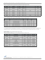
FCC-approved Antennas 57
IC (Industry Canada) Certification 60
Labeling Requirements 60
C-TICK (Australia) Certification 60
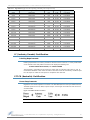
Power Requirements 60
Appendix B: Additional Information 61
1-Year Warranty 61
Ordering Information 61
Contact MaxStream 62

9XTend‐PKG‐E™EthernetRFModem–ProductManualv2.x4x[2007.01.04]
©2007MaxStream,Inc.,Confidential&Proprietary‐AllRightsReserved 4
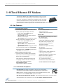
1.9XTendEthernetRFModem
The 9XTend RF Modem affords OEMs and integrators an easy-to-use RF
solution that sustains reliable delivery of data between remote devices.
Out-of-box, the modem is configured to immediately sustain long range
wireless links between devices. Simply feed serial data into one modem
then the data will surface on the other end of the wireless link. The
modem transfers a standard asynchronous serial data stream between devices.
1.1. Key Features
Long Range Data Integrity
1 Watt Power Output (variable 1mW - 1W)
Range (@9,600 bps throughput data rate):
• Indoor/Urban: up to 3000’ (900 m)
• Outdoor RF line-of-sight:
up to 14 miles (22 km) w/dipole antenna
• Outdoor RF line-of-sight:
up to 40 miles (64 km) w/high-gain antenna
Range (@115,200 bps throughput data rate):
• Indoor/Urban: up to 1500’ (450 m)
• Outdoor RF line-of-sight:
up to 7 miles (11 km) w/dipole antenna
• Outdoor RF line-of-sight:
up to 20 miles (32 km) w/high-gain antenna
Continuous RF data stream up to 115,200 bps
Receiver Sensitivity: -110 dBm (@ 9600 baud),
–100 dBm (@ 115200 baud)
Advanced Networking & Security
True Peer-to-Peer (no Master device required),
Point-to-Point, Point-to-Multipoint & Multidrop
Retries and Acknowledgements
FHSS (Frequency Hopping Spread Spectrum)
10 hopping channels, each with over 65,000
unique network addresses available
256-bit AES Encryption
(AES algorithm is FIPS-197 certified)
Low Power
7 - 28 V Supply Voltage
Serial Port and Cyclic
software sleep modes supported
Easy-to-Use
No configuration necessary for out-of box
RF communications
Free X-CTU Software
(Testing and configuration software)
RF Modems easily configured using
standard AT & binary commands
Transparent Operation
(Wireless links replace serial wires)
API Operation
(Frame-based communications)
Portable
(small form-factor easily designed into
a wide range of data systems)
Software-selectable I/O interfacing rates
Multiple data formats supported
(parity, start and stop bits, etc.)
XII™ Interference Immunity
No Master/Slave setup dependencies
Free & Unlimited Technical Support
1.1.1. Worldwide Acceptance
FCC Approved (USA) Refer to Appendix A [p56] for FCC Requirements.
Systems that include XTend RF Modems inherit MaxStream’s Certifications.
ISM (Industrial, Scientific & Medical) license-free 902-928 MHz frequency band
Manufactured under ISO 9001:2000 registered standards
ESD (Electrostatic Discharge) immunity - ESD-hardened and IEC1000-4-2 (Level 4) tested
9XTend RF Modems are optimized for use in the US, Canada, Australia and Israel

9XTend‐PKG‐E™EthernetRFModem–ProductManualv2.x4x[2007.01.04]
©2007MaxStream,Inc.,Confidential&Proprietary‐AllRightsReserved 5
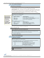
1.2. Specifications
The XTend-PKG-E RF Modem ships configured to provide immediate long range wireless links
between devices. The modem can be configured for additional functionality using standard AT and
binary commands [Refer to the Command Mode [p18] & RF Modem Configuration [p20] sections].
The built-in Ethernet interface makes RF data available to any TCP/IP network. Once connected to
a network, the XTend-PKG-E can be accessed through telnet; or, when used with the included Com
Port Redirector Software, it can be mapped to a com port and accessed as a serial device.
*Divideby2for18Vsupply(constantwattagefrom7‐28V)
Table1‐01. 9XTend‐PKG‐EEthernetRFModemSpecifications
9XTend 900 MHz Ethernet RF Modem Specifications
Performance @9600 bps Throughput Data Rate @115200 bps Throughput Data Rate
Transmit Power Output
(software selectable using PL command)
1mW - 1 Watt 1mW - 1 Watt
Indoor/Urban Range Up to 3000’ (900 m) Up to 1500’ (450 m)
Outdoor
RF line-of-sight Range
Up to 14 miles (22 km) w/ dipole antenna
Up to 40 miles (64 km) w/ high-gain antenna
Up to 7 miles (11 km) w/ dipole antenna
Up to 20 miles (32 km) w/ high-gain antenna
Interface Data Rate
(software selectable using BD command)
1200 – 230400 bps 1200 – 230400 bps
RF Data Rate 10,000 bps 125,000 bps
Receiver Sensitivity -110 dBm -100 dBm
Power Requirements
Supply Voltage 7 - 28V 7 - 28V
Receive Current 270 mA 270 mA
Serial Port Sleep Power Down 210 mA 210 mA
Idle Currents
(9V supply
voltage)
16 sec cyclic sleep (SM=8) 211 mA 210 mA
8 sec cyclic sleep (SM=7) 212 mA 210 mA
4 sec cyclic sleep (SM=6) 214 mA 211 mA
2 sec cyclic sleep (SM=5) 218 mA 212 mA
1 sec cyclic sleep (SM=4) 224 mA 215 mA
Networking & Security
Frequency 902-928 MHz
Spread Spectrum FHSS (Frequency Hopping Spread Spectrum)
Modulation FSK (Frequency Shift Keying)
Network Topologies Supported Peer-to-Peer (“Master/Slave” relationship not required), Point-to-Point, Point-to-Multipoint & Multidrop
Channel Capacity 10 hop sequences share 50 frequencies
Supported Network Protocols ARP, UDP, TCP, ICMP, Telnet, TFTP, AutoIP, DHCP, HTTP and SNMP
Encryption 256-bit AES Encryption – Refer to the KY Command to implement
Physical Properties
RF Modem Board Size 2.750” x 5.500” x 1.125” (6.99cm x 13.97” x 2.86cm)
Weight 7.1 oz. (200g)
Serial Connector RJ-45 Female Ethernet Connection
Operating Temperature -40 to 85º C (industrial)
Antenna
Connector RPSMA (Reverse-polarity SMA)
Type Half-wave dipole whip, 6.75” (17.15cm), 2.1 dBi gain
Impedance 50 ohms unbalanced
Certifications (partial list)
FCC Part 15.247 OUR-9XTEND
Industry Canada (IC) 4214A-9XTEND
Table1‐02. 9XTend‐PKG‐EEthernetRFModemSpecifications‐Relativetouser‐selectedTXPowerOutput
Power Requirements (TX currents relative to each TX Power Output option)
Transmit Power Output 1 mW 10 mW 100 mW 500 mW 1 W
Typical Transmit Current* (@115.2 Kbps)
9 VDC supply voltage
270 mA 290 mA 380 mA 600 mA 830 mA

9XTend‐PKG‐E™EthernetRFModem–ProductManualv2.x4x[2007.01.04]
©2007MaxStream,Inc.,Confidential&Proprietary‐AllRightsReserved 6
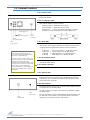
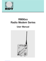
1.3. External Interface
1-01a. Power Switch
Figure1‐01. FrontView
Move Power Switch to the ON (up) position to power the XTend
Ethernet RF Modem.
1-01b. I/O & Power LEDs
LEDs indicate modem activity as follows:
Yellow (top LED) = Serial Data Out (to host)
Green (middle) = Serial Data In (from host)
Red (bottom) = Power/TX Indicator (Red light is on when
powered; it pulses on/off briefly during RF transmission.)
1-01c. RSSI LEDs
RSSI LEDs indicate the amount of fade margin present in an active
wireless link. Fade margin is defined as the difference between the
incoming signal strength and the modem's receiver sensitivity.
3 LEDs ON = Very Strong Signal (> 30 dB fade margin)
2 LEDs ON = Strong Signal (> 20 dB fade margin)
1 LED ON = Moderate Signal (> 10 dB fade margin)
0 LED ON = Weak Signal (< 10 dB fade margin)
1-01d. RJ-45 Ethernet Port
Standard Female RJ-45 connector is used to connect unshielded
twisted-pair CAT5 cabling.
1-01e. Power Connector*
7-28 VDC power connector
1-02a. Antenna Port
Figure1‐02. BackView The antenna port is a 50Ω RF signal connector for connecting to an
external antenna. The connector type is RPSMA (Reverse Polarity
SMA) female. The connector has threads on the outside of a barrel
and a male center conductor.
1-02b. Reset Switch
The Reset Switch is used to reset (re-boot) the RF modem and force
the modem into AT Command Mode.
To reset (re-boot) the modem: Press and then immediately release
the Reset Switch.
To force the modem into AT Command Mode (at the default through-
put data rate of the modem): Press the Reset Switch and keep it
depressed for at least two seconds, then release.
1‐01a.
PowerSwitch
1‐01b.
I/O&PowerLEDs
1‐01c.
RSSILEDs(allgr ee n)
1‐01d.RJ‐45port
1‐01e.
Power
Connector*
*TheEthernetRFModemdoesnotsup‐
portPower‐over‐Ethernet(PoE).The
devicecannotbepowereddirectlyfroma
PoEportonacompatiblehub.
However,itmaybeusefultosendpower
ontheunusedwiresoftheCAT‐5cablein
asituationwheretheradiowill
be
mountedinalocationthatoptimizesradio
coverage,butmaynothaveapoweroutlet
nearby.Thereareseveralthirdparty
devicesavailablethatcaninjectthepower
ontothecableandthenremoveitatthe
remoteside.
1‐02a.
Anten n aPort
1‐02b.
ResetSwitch

9XTend‐PKG‐E™EthernetRFModem–ProductManualv2.x4x[2007.01.04]
©2007MaxStream,Inc.,Confidential&Proprietary‐AllRightsReserved 7
2.SystemSetup
2.1. Data Radio System Components
MaxStream RF Modems were designed to provide reliable wireless links between devices contained
in a data system. The PKG-E Ethernet RF Modem allows integrators to connect the MaxStream
Modems into an Ethernet network.
The following devices will be used to describe a data system that includes the XTend-PKG-E Ether-
net RF Modem:
XTend-PKG-E Ethernet RF Modem ("PKG-E"): The Ethernet RF Modem is
an Ethernet-connected serial modem used for communication with other Max-
Stream serial modems. The Ethernet RF Modem is not a wireless Ethernet
Bridge intended for Ethernet connectivity on both the remote and base ends of
a wireless link.
XTend-PKG-R RS-232/485 RF Modem ("PKG-R"): The RS-232/485 RF
Modem is a serial modem that can be identified by its DB-9 serial port and 6-
switch DIP Switch.
XTend OEM RF Module ("OEM RF Module"): The OEM RF Module is
mounted inside all XTend-PKG RF Modems and may be integrated into OEM-
designed products to transmit and receive data over-the-air.
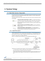
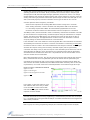
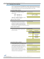
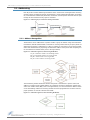
2.1.1. System Description
The PKG-E Ethernet RF Modem can be used as an access point in a network of MaxStream RS-
232/RS-485 RF Modems (or other OEM RF Module Embedded Devices). XTend RF Modems support
point-to-point, peer-to-peer, point-to-multipoint and multidrop network topologies. Below is an
example of a typical point-to-multipoint application:
Figure2‐01. XTend‐PKG‐EEthernetRFModeminaPoint‐to‐MultipointDataRadioSystem
The Ethernet-connected RF modem supports com port and Telnet connection options:
• "Com Port Redirector Software enables legacy serial applications to communicate with the
Ethernet RF Modem by forwarding serial data over Ethernet.
• "Telnet communicates directly to the Ethernet RF Modem using port 14001. Refer to the "Test
Communications (Telnet Loopback)" section [p12] for an example that by-passes the com
port.

9XTend‐PKG‐E™EthernetRFModem–ProductManualv2.x4x[2007.01.04]
©2007MaxStream,Inc.,Confidential&Proprietary‐AllRightsReserved 8
2.2. Com Port Communications
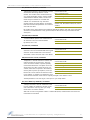
2.2.1. Install Software
The X-CTU and Com Port Redirector software facilitate communications through a PC com port.
Follow the instructions below to setup a com port for configuring and testing the RF modem.
Installation #1: X-CTU Software (version 4.8.0 or higher*)
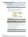
Use the X-CTU software to configure the Ethernet RF Modem and PC com port. The software is
divided into four tabs:
• PC Settings tab - Setup PC serial com ports to interface with RF modem
• Range Test tab - Test RF modem's range under varying environments
• Terminal tab - Test serial communications and set/read RF modem parameters
• Modem Configuration tab - Set/read RF modem parameters
Figure2‐02. TabsoftheX‐CTUSoftware
*ToverifyX‐CTUversionnumber,clickontheiconlocatedinthetop‐leftcorneroftheX‐CTUuserinterfaceand
thenselecttheʺAboutX‐CTU…ʺmenuitem.
To Install the X-CTU Software:
Installation #2: Ethernet Com Port Redirector
MaxStream provides com port redirection software that creates a com port in the operating sys-
tem that will forward serial data to the IP address of the Ethernet-connected RF modem. The
Ethernet RF Modem can then be accessed as though it were a serial device.
The Ethernet Com Port Redirector must be installed separately to enable the "Ethernet Com Ports"
sub-tab of the X-CTU "PC Settings" tab. If this software is not installed, the features under the
"Ethernet Com Ports" section are grayed and cannot be used.
The "Ethernet Com Ports" sub-tab enables user to perform functions such as the following:
• Discover Ethernet RF Modems on a network
• Setup serial com ports for XTend-PKG-E Ethernet RF Modems
• Identify, assign and modify Ethernet RF Modem IP addresses
To Install the Ethernet Com Port Redirector:
Double-click the "setup_X-CTU.exe" file then follow prompts of the installation screens. This file
is located on the MaxStream CD and under the 'Downloads' section of the following web page:
www.maxstream.net/helpdesk/download.php.
1. Double-click the "setup_ComPortRedirector.exe" file then follow prompts of the installation
screens. This file is located in the "software" folder of the MaxStream CD.
2. Re-boot the PC to complete installation.

9XTend‐PKG‐E™EthernetRFModem–ProductManualv2.x4x[2007.01.04]
©2007MaxStream,Inc.,Confidential&Proprietary‐AllRightsReserved 9
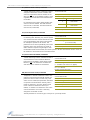
2.2.2. Setup Com Port and IP Address
The XTend-PKG-E Ethernet RF Modem supports DHCP (Dynamic Host Configuration Protocol) and
Auto IP protocols. Both protocols automatically assign IP addresses to nodes of a network.
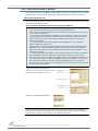
Ethernet RF Modem Discovery
The X-CTU Software provides an easy-to-use interface that searches a local network and then dis-
plays Ethernet RF Modems found.
Discover Ethernet RF Modem, Map Com Port & Assign IP Address:
Figure2‐03. EthernetComPortssub‐tab
(EthernetComPortssub‐tabisenabledbyinstalling
theEthernetComPortRedirectorSoftware.)
Figure2‐04. AssignIPAddressdialogbox
NOTE: If the Ethernet RF Modem is left in DHCP mode, it may become necessary to reconfigure a
mapped com port any time an IP address is re-assigned by the DHCP server. Dynamic addressing is
supported, but assigning a static IP address can simplify the application.
1. Install both the X-CTU and the Ethernet Com Port Redirector software [See "Install Soft-
ware" section on previous page]. Re-boot the PC if prompted to do so.
2. Launch the X-CTU Software and select the PC Settings tab; then select the "Ethernet Com
Ports" sub-tab. [Figure 2-03]
--> After the Com Port Redirector is installed (& PC is re-booted), a "Setup Com Port" dia-
log box will appear the first time the "Ethernet Com Ports sub-tab is selected. For subse-
quent uses of the sub-tab, select the 'New IP Address' button and proceed to step 4.
3. Select the 'OK' button.
--> All discovered PKG-E Ethernet RF Modems will be displayed in a new "Assign IP
Address" dialog box. [Figure 2-04]
4. Highlight one of the discovered Ethernet RF Modems (Modem IP and Hardware Addresses
are listed in the "… discovered Ethernet Modem" section) [Figure 2-04]. If an Ethernet
Modem is not discovered, enter the IP address manually in the "Enter IP Address…" box.
5. Select the 'OK' button.
--> Newly assigned Ethernet Modem is listed under the "Ethernet Com Ports" sub-tab and
the first available com port is assigned to it. Note that its status is "Queued as new".
6. Select the 'Apply' button [located in the 'Changes' section of the "Ethernet Com Ports" sub-
tab - Figure 2-03]. Even if an Ethernet RF Modem appears in the 'Ethernet Com Port' list,
the new com port cannot be used until changes are applied and the PC is re-booted.
7. Re-boot the PC; then re-launch the X-CTU Software. The com port can now be used to com-
municate with the RF modem.

9XTend‐PKG‐E™EthernetRFModem–ProductManualv2.x4x[2007.01.04]
©2007MaxStream,Inc.,Confidential&Proprietary‐AllRightsReserved 10
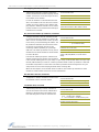
2.2.3. Assign Static IP Address
To assign a static IP address to the Ethernet RF Modem, follow the steps outlined below. A static IP
address may be necessary when:
• The Ethernet RF Modem and the host PC are on different subnets
• The Ethernet RF Modem IP address might be changed by a DHCP server
Configure a static IP address on a local network:
Figure2‐05. Properties&ChangeIPdialogboxes
2.2.4. Change Com Port Number
During Com Port Redirector setup, one com port is automatically assigned. Additional com ports
are user-assigned. Use the following steps to manually change a com port number:
Change Ethernet RF Modem's Com Port Number:
1. Install both the X-CTU Software and the Ethernet Com Port Redirector software [See "Com
Port Communications" section - p8]. Re-boot the PC if it has not been re-booted since the
installation of the Ethernet Com Port Redirector.
2. Launch the X-CTU Software and select the "PC Settings" tab; then select the "Ethernet Com
Ports" sub-tab [Figure 2-03]
--> After the Ethernet Com Port Redirector is installed (and PC is re-booted), a "Setup Com
Port" dialog box will appear the first time the "Ethernet Com Ports" sub-tab is selected. The
following steps are written under the assumption the sub-tab has already been selected at
least one time.
3. Select the "Discover modems" button to display which modems are on-line and which are
not; then click the 'OK' button of the "Discover Ethernet Modems" dialog box.
4. Click-on and highlight an Ethernet RF Modem from the 'Ethernet Com Ports' list.
5. Select the 'Com Port Properties' button [Figure 2-03].
6. Select the 'Modify' button of the "Properties" dialog box [Figure 2-05].
7. Type a new IP address; then select the 'OK' button [Figure 2-05].
8. Select the 'OK' button of the "Properties" dialog box.
9. Select the 'Apply' button that is under the 'Changes' section of the "Ethernet Com Ports"
sub-tab.
--> XTend-PKG-E Ethernet RF Modem re-boots and the new IP Address is saved.
1. Once the Ethernet RF Modem is recognized and displayed under the "Ethernet Com Ports"
sub-tab, select the 'New Com Port' button. Follow the steps outlined in the "Ethernet RF
Modem Discovery" section [p9].
2. Type-in the IP Address of the Ethernet Modem and highlight a com port number; then
select the 'OK' button.
3. Select the 'Apply' button; then re-boot the PC if prompted to do so.
4. Go to the 'Ethernet Com Ports' sub-tab of the X-CTU Software's 'PC Settings' tab.
5. Highlight the old com port entry, select the 'Delete Com Port' button, then select the 'Apply'
button.

9XTend‐PKG‐E™EthernetRFModem–ProductManualv2.x4x[2007.01.04]
©2007MaxStream,Inc.,Confidential&Proprietary‐AllRightsReserved 11
2.2.5. Test Communications (X-CTU Loopback)
When testing a wireless link, consider using the following components:
• XTend-PKG-E Ethernet RF Modem (connected to a local network)
• XTend-PKG-R RS-232/485 RF Modem (w/ loopback adapter)
• PC (connected to a local network)
• Accessories (Loopback adapter, CAT5 UTP cable, power supplies and RPSMA antennas)
Hardware Setup for Loopback Test:
Figure2‐06. HardwareSetupforTestingaWirelessLink
Test Wireless Link (X-CTU Method):
Figure2‐07. TerminalTabofMaxStreamʹsX‐CTUSoftware
1. Connect the XTend-PKG-E (Ethernet) RF Modem and a PC to active Ethernet ports of the
same local network using CAT5 cables (included w/ PKG-EA accessories package).
2. Attach the serial loopback adapter to the DB-9 serial connector of the XTend-PKG-R (RS-
232) RF Modem. The serial loopback adapter configures the PKG-R RF Modem to function
as a repeater by looping serial data back into the modem for retransmission.
3. Configure the PKG-R (RS-232) RF Modem for RS-232 operation using
the built-in DIP Switch. Dip Switch 1 should be ON (up) and the
remaining switches should be OFF (down).
4. Attach RPSMA antennas to both RF Modems.
5. Power both RF Modems with power supplies (included w/ accessories package).
1. Follow the steps in the "Ethernet RF Modem Discovery" section [p9].
2. Setup hardware as shown in the "Hardware Setup…" steps above [Figure 2-06].
3. Select the 'PC Settings' tab of the X-CTU Software; then highlight the Com Port that is for-
warded to the PKG-E (Ethernet) RF Modem.
--> Make sure PC com port settings (Baud rate, Parity, etc.) on the "PC Settings" tab match
those of the Ethernet RF Modem.
4. Select the 'Terminal' tab of the X-CTU Software.
5. Begin typing characters into the terminal window.
--> Characters typed in the terminal should be echoed back to the screen [Figure 2-07].
Sent characters appear in blue and received characters in red. With each character typed,
the 'Data Out' and 'Data In' LEDs should flash briefly on each of the RF Modems.
--> To double-check the wireless link, turn off the power going to the remote PKG-R (RS-
232) RF Modem and leave the PKG-E Modem turned on. Type characters into the Terminal
Window of the X-CTU Software and note that characters are not echoed back.

9XTend‐PKG‐E™EthernetRFModem–ProductManualv2.x4x[2007.01.04]
©2007MaxStream,Inc.,Confidential&Proprietary‐AllRightsReserved 12
2.3. Telnet Communications
In addition to com port communications, Telnet communications are also supported.
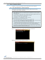
2.3.1. Test Communications (Telnet Loopback)
A wireless link can be tested by connecting to the specific IP address and port number.
Test a Wireless Link (Telnet Connection):
Figure2‐08. TelnetInterface(connecttoPKG‐EhavinganIPaddressof192.168.0.168)
Figure2‐09. TelnetInterface(Sent&Echoedbackcharacters)
1. Follow steps in the "Ethernet RF Modem Discovery" section [p9].
2. Setup hardware as shown in the 'Hardware Setup for Loopback Test' section of previous
page [Figure 2-06].
3. If using Windows: Select (Start ' Run); then type "cmd" (without quotation marks) in the
text box of the "Run" dialog box. Then select the 'OK' button.
If using Linux or UNIX: Run a command shell.
If using Mac OS X: Run (Applications ' Utilities ' Terminal).
[Remaining steps are for Microsoft Windows users]
4. At the command prompt, type: telnet xxx.xxx.xxx.xxx 14001 <CR>
("xxx.xxx.xxx.xxx" is the IP address of the Ethernet RF Modem, "14001" is the port number
and "<CR>" stands for carriage return or 'Enter' key.) [Figure 2-08]
5. Begin typing characters into the Telnet session window [Figure 2-09].
--> Characters typed should be echoed back to the screen. With each character typed, the
"Data Out" and "Data In" LEDs should flash briefly on each of the PKG RF Modems.
The wireless link can be double-checked by turning off the XTend-PKG-R RS-232/485 RF
Modem (leaving the PKG-E Ethernet RF Modem on) and sending characters. When the PKG-
R is turned off, characters should not be echoed back.

9XTend‐PKG‐E™EthernetRFModem–ProductManualv2.x4x[2007.01.04]
©2007MaxStream,Inc.,Confidential&Proprietary‐AllRightsReserved 13
3.RFModemOperation
WARNING: When operating at 1 Watt power output, observe a minimum separation distance of 2' (0.6m) between
modems. Transmitting in close proximity of other modems can damage modem front ends.
3.1. Serial Communications
3.1.1. Transparent Operation
By default, XTend RF Modems operate in Transparent Mode. The modems act as a serial line
replacement - all UART data received through the DI pin is queued up for RF transmission. When
RF data is received, the data is sent out the DO pin.
When the RO (Packetization Timeout) parameter threshold is satisfied, the modem attempts to ini-
tialize an RF transmission. If the modem cannot immediately transmit (for instance, if it is already
receiving RF data), the serial data continues to be stored in the DI Buffer. Data is packetized and
sent at any RO timeout or when the maximum packet size is received.
The modem operates as described above unless the Command Mode Sequence is detected. The
Command Mode Sequence consists of three copies of the command sequence character [CC
parameter] surrounded by the before and after guard times [BT & AT parameters].
If the DI buffer becomes full, hardware or software flow control must be implemented in order to
prevent overflow (loss of data between the host and modem).
3.1.2. API Operation
API (Application Programming Interface) Operation is an alternative to the default Transparent
Operation. The API is frame-based and extends the level to which a host application can interact
with the networking capabilities of the module. When in API mode, all data entering and leaving
the RF modem is contained in frames that define operations or events within the modem.
Transmit Data Frames (received through the DI (Data In) pin) include:
• 16-bit address
Receive Data Frames (sent out the DO (Data Out) pin) include:
• Showing a received RF packet (16 bits only)
• Response to a TX (Transmit) packet
• Showing events such as hardware reset, watchdog reset, asynchronous events, etc.
The modem will send data frames to the application containing status packets; as well as source,
RSSI and payload information from received data packets.
API operation option facilitates many operations such as the examples cited below:
To implement API operations, refer to ‘API Operation’ sections [p42].
-> Change destination addresses without having to enter command mode
-> Receive success/failure status of each RF packet
-> Identify the source address of each received packet

9XTend‐PKG‐E™EthernetRFModem–ProductManualv2.x4x[2007.01.04]
©2007MaxStream,Inc.,Confidential&Proprietary‐AllRightsReserved 14
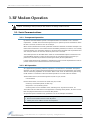
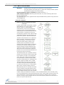
3.2. Modes of Operation
XTend RF Modems operate in five modes.
Figure3‐01. ModesofOperation
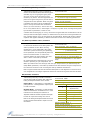
3.2.1. Idle Mode
When not receiving or transmitting data, the RF modem is in Idle Mode. The modem shifts into the
other modes of operation under the following conditions:
• Transmit Mode (Serial data is received in the DI Buffer)
• Receive Mode (Valid RF data is received through the antenna)
• Sleep Mode (Sleep Mode condition is met)
• Command Mode (Command Mode Sequence is issued)
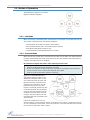
3.2.2. Transmit Mode
When the first byte of serial data is received from the UART in the DI buffer, the modem attempts
to shift to Transmit Mode and initiate an RF connection with other modems. After transmission is
complete, the modem returns to Idle Mode.
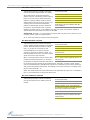
RF transmission begins after either of the following criteria is met:
Figure3‐02. TransmitModeDataFlow
The character timeout trigger can be
disabled by setting RO to zero. In this
case, transmission will not begin until
RB bytes have been received and are
pending for RF transmission. The RB
parameter may be set to any value
between 1 and the RF packet size [refer
to PK (Max RF Packet Size) parameter],
inclusive. Note that transition to Trans-
mit Mode cannot take place during RF
reception; the RF reception must com-
plete before the radio can transition into
Transmit Mode.
If RB or RO conditions are met, the
modem initializes a communications channel. Serial data in the DI buffer is grouped into RF pack-
ets (up to 2048 bytes in each packet, refer to PK Command), converted to RF data and is transmit-
ted over-the-air until the DI buffer is empty.
1. RB bytes have been received by the UART and are pending for RF transmission.
[Refer to the RB (Packetization Threshold) Command]
2. At least one character has been received by the UART and is pending for RF transmission;
and RO character times of silence been observed on the UART.
[Refer to the RO (Packetization Timeout) Command]

9XTend‐PKG‐E™EthernetRFModem–ProductManualv2.x4x[2007.01.04]
©2007MaxStream,Inc.,Confidential&Proprietary‐AllRightsReserved 15
Channel initialization is the process of sending an RF initializer that synchronizes receiving
modems with the transmitting modem. During channel initialization, incoming serial data accumu-
lates in the DI buffer.
RF data, which includes the payload data, follows the RF initializer. The payload includes up to the
maximum packet size (PK Command) bytes. As the TX modem nears the end of the transmission,
it inspects the DI buffer to see if more data exists to be transmitted. This could be the case if more
than PK bytes were originally pending in the DI buffer or if more bytes arrived from the UART after
the transmission began. If more data is pending, the transmitting modem assembles a subsequent
packet for transmission.
Refer to the ‘RF Communication Modes’ section to view state diagrams that illustrate channel ini-
tialization and the sequence of events that follow.
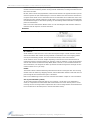
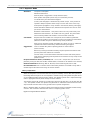
RF Packet
Figure3‐03. RFPacketComponents
* When streaming multiple RF packets, the RF Initializer is only sent in front of the first packet.
RF Initializer
An RF initializer is sent each time a new connection sequence begins. The RF initializer contains
channel information that notifies receiving modems of information such as the hopping pattern
used by the transmitting modem. The first transmission always sends an RF initializer.
An RF initializer can be of various lengths depending on the amount of time determined to be
required to prepare a receiving modem. For example, a wake-up initializer is a type of RF initializer
used to wake remote modems from Sleep Mode (Refer to the FH, LH, HT and SM Commands for
more information). The length of the wake-up initializer should be longer than the length of time
remote modems are in cyclic sleep.
Header
The header contains network addressing information that filters incoming RF data. The receiving
modem checks for matching a Hopping Channel, VID and Destination Address. Data that does not
pass through all three network filter layers is discarded.
Refer to the ‘Addressing’ section of the “RF Communication Modes” chapter for more information.
CRC (Cyclic Redundancy Check)
To verify data integrity and provide built-in error checking, a 16-bit CRC (Cyclic Redundancy
Check) is computed for the transmitted data and attached to the end of each RF packet. On the
receiving end, the receiving modem computes the CRC on all incoming RF data. Received data that
has an invalid CRC is discarded [refer to the ‘Receive Mode’ section].

9XTend‐PKG‐E™EthernetRFModem–ProductManualv2.x4x[2007.01.04]
©2007MaxStream,Inc.,Confidential&Proprietary‐AllRightsReserved 16
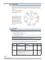
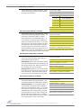
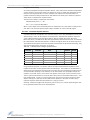
3.2.3. Receive Mode
If a modem detects RF data while operating in Idle Mode, the modem transitions to Receive Mode
to start receiving RF packets. Once a packet is received, the modem checks the CRC (cyclic redun-
dancy check) to ensure that the data was transmitted without error. If the CRC data bits on the
incoming packet are invalid, the packet is discarded. If the CRC is valid, the packet proceeds to the
DO Buffer.
Figure3‐04. ReceiveModeDataFlow
*Refertothe‘A d d r e ss Recognition’sec‐
tionformoreinformationregarding
addressrecognition.
The modem returns to Idle Mode
when valid RF data is no longer
detected or after an error is
detected in the received RF data. If
serial data is stored in the DI
buffer while the modem is in
Receive Mode, the serial data will
be transmitted after the modem is
finished receiving data and returns
to Idle Mode.
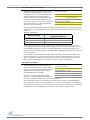
3.2.4. Sleep Mode
Software Sleep
Sleep Modes enable the modem to enter states of low-power consumption when not in use. Three
software Sleep Modes are supported:
• Serial Port Sleep (Wake on Serial Port activity)
• Cyclic Sleep (Wake on RF activity)
In order to enter Sleep Mode, the following condition must be met (in addition to the modem hav-
ing a non-zero SM parameter value):
When in Sleep Mode, the modem will not transmit or receive data until the modem first transitions
to Idle Mode. All Sleep Modes are enabled and disabled using SM Command. Transitions into and
out of Sleep Modes are triggered by various mechanisms as shown in the table below.
The modem is idle (no data transmission or reception) for the amount of time defined by the ST
(Time before Sleep) parameter. [NOTE: ST is only active when SM = 4-5.]
Table3‐01. SummaryofSleepModeConfigurations
Sleep Mode
(Setting)
Transition into
Sleep Mode
Transition out of Sleep
Mode (wake)
Related
Commands
Power
Consumption
Serial Port Sleep
(SM = 2)
Automatic transition to Sleep Mode
occurs after a user-defined period of
inactivity (no transmitting or receiving of
data).
Period of inactivity is defined by the ST
(Time before Sleep) Command.
When a serial byte is received on
the DI pin
(SM), ST < 210 mA
Cyclic Sleep
(SM = 4 - 8)
RF modem transitions in and out of Sleep Mode in cycles (user-selectable
wake-up interval of time is set using the SM command). The cyclic sleep
interval of time must be shorter than the interval of time that is defined by the
LH (Wake-up Initializer TImer) command.
Note: The modem can be forced into Idle Mode using the SLEEP pin if the
PW (Pin Wake-up) command is issued.
(SM), ST, HT,
LH, PW
< 210 - 224 mA
when sleeping
(SM=4, 1 sec.,
@120K baud)

9XTend‐PKG‐E™EthernetRFModem–ProductManualv2.x4x[2007.01.04]
©2007MaxStream,Inc.,Confidential&Proprietary‐AllRightsReserved 17
The SM (Sleep Mode) command is central to setting all Sleep Mode configurations. By default,
Sleep Modes are disabled (SM = 0) and the modem remains in Idle/Receive Mode. When in this
state, the modem remains constantly ready to respond to serial or RF activity.
Serial Port Sleep (SM = 2)
• Wake on serial port activity
• Typical power-down current: < 210 mA
Serial Port Sleep is a Sleep Mode in which the modem runs in a low power state until serial data is
detected on the DI pin.
The period of time the modem sleeps is determined by ST (Time before Sleep) Command. Once a
character is received through the DI pin, the modem returns to Idle Mode and is fully operational.
Cyclic Sleep (SM = 4-8)
• Typical Power-down Current: < 210 - 224 mA (when asleep)
Cyclic Sleep Modes allow modems to periodically wake and check for RF data. The modem wakes
according to the times designated by the Cyclic sleep settings. If the modem detects a wake-up
initializer during the time it is awake, the modem synchronizes with the transmitting modem and
receives data after the wake-up initializer runs its duration. Otherwise, the modem returns to
Sleep Mode and continues to cycle in and out of activity until a wake-up initializer is detected.
While the modem is in Cyclic Sleep Mode, CTS
(GPO1) is de-asserted (high) to indicate that data
should not be sent to the modem. When the modem awakens to listen for data, GPO1 is asserted
and any data received on the DI Pin is transmitted. The PWR pin is also de-asserted (low) when
the modem is in Cyclic Sleep Mode.
The modem remains in Sleep Mode for a user-defined period of time ranging from 0.5 seconds to
16 seconds (SM parameters 4 through 8). After this interval of time, the modem returns to Idle
Mode and listens for a valid data packet for 100 ms. If the modem does not detect valid data (on
any frequency), the modem returns to Sleep Mode. If valid data is detected, the modem transi-
tions into Receive Mode and receives the incoming RF packets. The modem then returns to Sleep
Mode after a period of inactivity determined by the ST "Time before Sleep" parameter.
The modem can also be configured to wake from cyclic sleep when the SLEEP pin is de-asserted.
To configure a modem to operate in this manner, PW (Pin Wake-up) Command must be issued.
Once the SLEEP pin is de-asserted, the modem is forced into Idle Mode and can begin transmitting
or receiving data. It remains active until data is no longer detected for the period of time specified
by the ST Command, at which point it resumes its low-power cyclic state.
Cyclic Scanning. Each RF transmission consists of an RF Initializer and payload. The RF initializer
contains initialization information and all receiving modems must wake during the wake-up initial-
izer portion of data transmission in order to be synchronized with the transmitting modem and
receive the data.
The cyclic interval time defined by SM (Sleep Mode) Command must be shorter than the interval time
defined by LH (Wake-up Initializer Timer).

9XTend‐PKG‐E™EthernetRFModem–ProductManualv2.x4x[2007.01.04]
©2007MaxStream,Inc.,Confidential&Proprietary‐AllRightsReserved 18
3.2.5. Command Mode
To modify or read modem parameters, the modem must first enter into Command Mode (state in
which incoming characters are interpreted as commands). Two command types are supported:
• AT Commands
• Binary Commands
For modified parameter values to persist in the modem registry, changes must be saved to non-
volatile memory using the WR (Write) command. Otherwise, parameters are restored to previously
saved values when the modem is powered off and then on again.
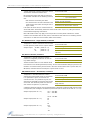
AT Command Mode
To Enter AT Command Mode:
Default AT Command Mode Sequence (for transition to Command Mode):
• No characters sent for one second [refer to the BT (Guard Time Before) Command]
• Input three plus characters (“+++”) within one second
[refer to the CC (Command Sequence Character) Command.]
• No characters sent for one second [refer to the AT (Guard Time After) Command.]
All of the parameter values in the sequence can be modified to reflect user preferences.
To Send AT Commands:
Figure3‐05.SyntaxforsendingAT Commands
To read a parameter value stored in the modem register, leave the parameter field blank.
The preceding example would change the modem’s Destination Address to "0x1F". To store the
new value to non-volatile (long term) memory, the Write (ATWR) command must subsequently be
sent before powering off the modem.
System Response. When a command is sent to the modem, the modem will parse and execute
the command. Upon successful execution of a command, the modem returns an “OK” message. If
execution of a command results in an error, the modem returns an “ERROR” message.
To Exit AT Command Mode:
For an example of programming the RF modem using AT Commands and descriptions of each config-
urable parameter, refer to the "RF Modem Configuration" chapter [p20].
1. Send the 3-character command sequence "+++" and observe guard times before and after
the command characters. [refer to ‘Default AT Command Mode Sequence’ below.] The ‘Ter-
minal’ tab (or other serial communications software) of the X-CTU Software can be used to
enter the sequence.
[OR]
2. Assert (low) the CONFIG
pin and turn the power going to the modem off and back on (or
pulse the SHDN
pin).
[If the modem is mounted to a MaxStream RS-232/485 Interface Board, the result can be
achieved by pressing the configuration switch down for 2 seconds.]
Send AT commands and parameters using the syntax shown below.
1. If no valid AT Commands are received within the time specified by CT (Command Mode
Timeout) Command, the modem automatically returns to Idle Mode.
[OR]
2. Send ATCN (Exit Command Mode) Command.

9XTend‐PKG‐E™EthernetRFModem–ProductManualv2.x4x[2007.01.04]
©2007MaxStream,Inc.,Confidential&Proprietary‐AllRightsReserved 19
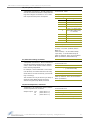
Binary Command Mode
Sending and receiving parameter values using binary commands is the fastest way to change
operating parameters of the modem. Binary commands are used most often to sample signal
strength [refer to DB (Received Signal Strength) parameter] and/or error counts; or to change
modem addresses and channels for polling systems when a quick response is necessary. Since the
sending and receiving of parameter values takes place through the same serial data path as 'live'
data (received RF payload), interference between the two types of data can be a concern.
Common questions about using binary commands:
• What are the implications of asserting CMD while live data is being sent or received?
• After sending serial data, is there a minimum time delay before CMD can be asserted?
• Is a time delay required after CMD is de-asserted before payload data can be sent?
• How does one discern between live data and data received in response to a command?
The CMD pin (GPI1) must be asserted in order to send binary commands to the modem. The CMD
pin can be asserted to recognize binary commands anytime during the transmission or reception
of data. The status of the CMD signal is only checked at the end of the stop bit as the byte is
shifted into the serial port. The application does not allow control over when data is received,
except by waiting for dead time between bursts of communication.
If the command is sent in the middle of a stream of payload data to be transmitted, the command
will essentially be executed in the order it is received. If the modem is continuously receiving data,
the radio will wait for a break in the received data before executing the command. The CTS
signal
will frame the response coming from the binary command request [refer to figure below].
A minimum time delay of 100 µs (after the stop bit of the command byte has been sent) must be
observed before the CMD pin can be de-asserted. The command executes after all parameters
associated with the command have been sent. If all parameters are not received within 0.5 sec-
onds, the modem returns to Idle Mode.
Note: When parameters are sent, they are two bytes long with the least significant byte sent first.
Binary commands that return one parameter byte must be written with two parameter bytes.
Commands can be queried for their current value by sending the command logically ORed (bit-
wise) with the value 0x80 (hexadecimal) with CMD asserted. When the binary value is sent (with
no parameters), the current value of the command parameter is sent back through the DO pin.
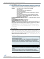
Figure3‐06. BinaryCommandWritethenRead
Signal#4isCMD
Signal#1istheDIsignal
Signal#2istheDOsignalfromtheradio
Signal#3isCTS
In this graph, a value was written to a reg-
ister and then read out to verify it. While
not in the middle of other received data,
note that the CTS
signal outlines the data
response out of the modem.
IMPORTANT: In order for the modem to recognize a binary command, the RT (GPI1 Configuration)
parameter must be set to one. If binary programming is not enabled (RT parameter value is not equal
to ‘1’), the modem will not recognize that the CMD pin is asserted and therefore will not recognize the
data as binary commands.
Refer to [p21] for a binary programming example (DT command example returns two bytes).

9XTend‐PKG‐E™EthernetRFModem–ProductManualv2.x4x[2007.01.04]
©2007MaxStream,Inc.,Confidential&Proprietary‐AllRightsReserved 20
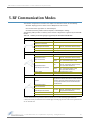
4.RFModemConfiguration
4.1. Programming Examples
Refer to the ‘Command Mode’ section [p18] for information
regarding entrance into Command Mode, sending AT com-
mands and exiting Command Mode.
4.1.1. Configuration Setup Options
After installing the X-CTU and Com Port Redirector Software
[p8] to a PC, use one of the connection options below to send
commands to the XTend-PKG-E Ethernet RF Modem.
Option #1 - Local Network Connection
Connect a PC and the Ethernet RF Modem to active Ethernet connections of the same local net-
work [as shown in the figure below].
Figure4‐01. LocalNetworkConnection
Option #2 - Direct PC Connection
Connect the Ethernet RF Modem directly to the PC through the PC's Ethernet port [as shown in the
figure below].
Figure4‐02. DirectPCConnection
Configuration Setup:
1. Install both the X-CTU Software and the Ethernet Com Port Redirector [See 'Install Soft-
ware' [p8] section for more information].
2. Connect the Ethernet RF Modem to a PC using either a Local Network [Figure 4-01] or a
Direct PC [Figure 4-02] connection.
3. Follow the steps outlined in the 'Ethernet RF Modem Discovery' section [p9] to identify the
com port that will be used to configure the RF modem.
4. Launch the X-CTU Software on the PC and select the PC Settings tab.
5. Make sure values shown in the fields of the 'Com Port Setup' section match those of the
Ethernet RF Modem.
[Example is continued on the following page.]
Examplesinthissectioncitethe
useofMaxStreamʹsX‐CTUSoft‐
wareforprogrammingtheRF
modem.Otherprogramssuchas
TelnetSoftwarecanalsobeused
toprogramthemodem.
Page is loading ...
Page is loading ...
Page is loading ...
Page is loading ...
Page is loading ...
Page is loading ...
Page is loading ...
Page is loading ...
Page is loading ...
Page is loading ...
Page is loading ...
Page is loading ...
Page is loading ...
Page is loading ...
Page is loading ...
Page is loading ...
Page is loading ...
Page is loading ...
Page is loading ...
Page is loading ...
Page is loading ...
Page is loading ...
Page is loading ...
Page is loading ...
Page is loading ...
Page is loading ...
Page is loading ...
Page is loading ...
Page is loading ...
Page is loading ...
Page is loading ...
Page is loading ...
Page is loading ...
Page is loading ...
Page is loading ...
Page is loading ...
Page is loading ...
Page is loading ...
Page is loading ...
Page is loading ...
Page is loading ...
Page is loading ...
-
 1
1
-
 2
2
-
 3
3
-
 4
4
-
 5
5
-
 6
6
-
 7
7
-
 8
8
-
 9
9
-
 10
10
-
 11
11
-
 12
12
-
 13
13
-
 14
14
-
 15
15
-
 16
16
-
 17
17
-
 18
18
-
 19
19
-
 20
20
-
 21
21
-
 22
22
-
 23
23
-
 24
24
-
 25
25
-
 26
26
-
 27
27
-
 28
28
-
 29
29
-
 30
30
-
 31
31
-
 32
32
-
 33
33
-
 34
34
-
 35
35
-
 36
36
-
 37
37
-
 38
38
-
 39
39
-
 40
40
-
 41
41
-
 42
42
-
 43
43
-
 44
44
-
 45
45
-
 46
46
-
 47
47
-
 48
48
-
 49
49
-
 50
50
-
 51
51
-
 52
52
-
 53
53
-
 54
54
-
 55
55
-
 56
56
-
 57
57
-
 58
58
-
 59
59
-
 60
60
-
 61
61
-
 62
62


Digi 9XTEND PKG AND MODULE User manual
- Category
- Networking
- Type
- User manual
- This manual is also suitable for
Ask a question and I''ll find the answer in the document
Finding information in a document is now easier with AI
Related papers
-
Digi 9XTEND PKG AND MODULE User guide
-
-
Digi 9XTEND PKG AND MODULE User guide
-
-
-
-
-
-
-
Other documents
-
B&B Electronics 9XTend-PKG-E User manual
-
Hughes External Antenna User guide
-
Sunricher SR-3001DIN User manual
-
Warwick X7220 User manual
-
Omega UWTC-REC Series Owner's manual
-
 Xpress XEB09-C User manual
-
 Xpress Network Router XEB09-C User manual
-
Eaton 455U-D User manual
-
 RDT RM96xx User manual
-
Black Box MDR210A-485 User manual


