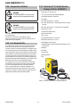
ESAB ESAB Fabricator® 211i 3-IN-1 Multi Process Welding Systems User manual
- Category
- Welding System
- Type
- User manual

A-12922
210
115V
208/230V
3163339
Révision : AA Issue Date: September 22, 2015 Manual No.: 0-5450
Service
Manual
ESAB Fabricator
®
211i
3-IN-1 Multi Process
Welding Systems
esab.com

WE APPRECIATE YOUR BUSINESS!
Congratulations on your new ESAB product. We are proud to have you as our customer and will strive to
provide you with the best service and reliability in the industry. This product is backed by our extensive
warranty and world-wide service network. To locate your nearest distributor or service agency, visit us on
the web at www.esab.com.
This Operating Manual has been designed to instruct you on the correct use and operation of your ESAB
product. Your satisfaction with this product and its safe operation is our ultimate concern. Therefore please
take the time to read the entire manual, especially the Safety Precautions. They will help you to avoid potential
hazards that may exist when working with this product.
YOU ARE IN GOOD COMPANY!
The Brand of Choice for Contractors and Fabricators Worldwide.
ESAB is a Global Brand of manual and automation Plasma Cutting Products.
We distinguish ourselves from our competition through market-leading, dependable products that have stood
the test of time. We pride ourselves on technical innovation, competitive prices, excellent delivery, superior
customer service and technical support, together with excellence in sales and marketing expertise.
Above all, we are committed to developing technologically advanced products to achieve a safer working
environment within the welding industry.

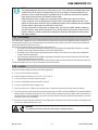
!
WARNING
Read and understand this entire Manual and your employer’s safety practices before install-
ing, operating, or servicing the equipment.
While the information contained in this Manual represents the Manufacturer's best judgement,
the Manufacturer assumes no liability for its use.
Plasma Cutting Power Supply
ESAB Fabricator
®
211i 3-in-1 Multi Process Welding Systems™
Service Manual Number 0-5450
Published by:
ESAB
2800 Airport Rd.
Denton, TX 76208
www.esab.com
Copyright 2015 by ESAB
All rights reserved.
Reproduction of this work, in whole or in part, without written permission of the
publisher is prohibited.
The publisher does not assume and hereby disclaims any liability to any party for
any loss or damage caused by any error or omission in this Manual, whether such
error results from negligence, accident, or any other cause.
Original Publication Date: September 22, 2015
Revision Date:
Record the following information for Warranty purposes:
Where Purchased:_______________________________ __________
Purchase Date:__________________________________ __________
Power Supply Serial #:___________________________ __________
Torch Serial #:___________________________________ __________

Be sure this information reaches the operator.
You can get extra copies through your supplier.
CAUTION
These INSTRUCTIONS are for experienced operators. If you are not fully familiar
with the principles of operation and safe practices for arc welding and cutting equip-
ment, we urge you to read our booklet, “Precautions and Safe Practices for Arc
Welding, Cutting, and Gouging,” Form 52-529. Do NOT permit untrained persons to
install, operate, or maintain this equipment. Do NOT attempt to install or operate this
equipment until you have read and fully understand these instructions. If you do not
fully understand these instructions, contact your supplier for further information. Be
sure to read the Safety Precautions before installing or operating this equipment.
USER RESPONSIBILITY
This equipment will perform in conformity with the description thereof contained in this manual and accom-
panying labels and/or inserts when installed, operated, maintained and repaired in accordance with the instructions
provided. This equipment must be checked periodically. Malfunctioning or poorly maintained equipment should not be
used. Parts that are broken, missing, worn, distorted or contaminated should be replaced immediately. Should such re-
pair or replacement become necessary, the manufacturer recommends that a telephone or written request for service
advice be made to the Authorized Distributor from whom it was purchased.
This equipment or any of its parts should not be altered without the prior written approval of the manufacturer.
The user of this equipment shall have the sole responsibility for any malfunction which results from improper use,
faulty maintenance, damage, improper repair or alteration by anyone other than the manufacturer or a service facility
designated by the manufacturer.
!
READ AND UNDERSTAND THE INSTRUCTION MANUAL BEFORE INSTALLING OR
OPERATING.
PROTECT YOURSELF AND OTHERS!

TABLE OF CONTENTS
SECTION 1: SAFETY .................................................................................................... 1-1
1.0 Safety Precautions....................................................................................................... 1-1
SECTION 2:
INTRODUCTION ................................................................................................. 2-1
2.02 Equipment Identification .............................................................................................. 2-1
2.03 Receipt Of Equipment .................................................................................................. 2-1
2.04 Description .................................................................................................................. 2-1
2.01 How To Use This Manual ............................................................................................. 2-1
2.05 Transportation Methods .............................................................................................. 2-2
2.06 User Responsibility ..................................................................................................... 2-2
2.07 Fabricator 211i Portable System Package (Part No. W1004201) ................................ 2-2
SECTION 3:
SAFETY AND INSTALLATION .................................................................................. 3-1
3.01 Duty Cycle ................................................................................................................... 3-1
3.02 Specifications .............................................................................................................. 3-2
3.03 Environment ................................................................................................................ 3-3
3.04 Location ...................................................................................................................... 3-3
3.05 Ventilation ................................................................................................................... 3-4
3.06 Electricity Supply ........................................................................................................ 3-4
3.07 Electromagnetic Compatibility ..................................................................................... 3-6
3.08 Victor Regulator .......................................................................................................... 3-7
3.09 Leak Testing The System ............................................................................................. 3-9
3.10 When You Finish Using The Regulator ........................................................................ 3-9
3.11 Storage Of The Regulator ............................................................................................ 3-9
3.12 Volt-Ampere Curves .................................................................................................. 3-10
SECTION 4:
Operation ......................................................................................................... 4-1
4.01 Fabricator 211i Power Source Controls, Indicators And Features ................................ 4-1
4.02 Attaching The TWECO Fusion 220A MIG Gun.............................................................. 4-7
4.03 Installing 33/44 lb Spool (12" diameter) ..................................................................... 4-8
4.04 Installing 12.5 lb Spool ( 8" diameter) ......................................................................... 4-9
4.05 Installing 1 lb Spool (4" diameter) ............................................................................. 4-10
4.06 Inserting Wire Into The Wire Feed Mechanism .......................................................... 4-11
4.07 Feed Roll Pressure Adjustment ................................................................................. 4-12
4.08 Changing the Feed Roll .............................................................................................. 4-12
4.09 Wire Reel Brake ......................................................................................................... 4-13
4.10 Setup For MIG (GMAW) Welding With Gas Shielded MIG Wire ................................. 4-13
4.11 Setup For MIG (FCAW) Welding With Flux Core (Gasless) Wire ................................ 4-15
4.12 Setup For SPOOL GUN MIG (GMAW) Welding With Gas Shielded MIG Wire ............ 4-16
4.13 Setup For LIFT TIG (GTAW) Welding ......................................................................... 4-18
4.14 Setup For STICK (SMAW) Welding ........................................................................... 4-19
SECTION 5:
TROUBLESHOOTING ............................................................................................ 5-1
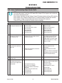
5.01 Basic Troubleshooting-Power Source Faults ............................................................... 5-1
5.02 Routine Service and Calibration Requirements ........................................................... 5-2
5.03 Check Unit before Applying Power .............................................................................. 5-4
5.04 Test Equipment and Tools Needed for Troubleshooting and Servicing ........................ 5-5
5.05 Visually Inspect ........................................................................................................... 5-5
5.06 Preliminary DC Bus Measurement of the Power PCB .................................................. 5-5

TABLE OF CONTENTS
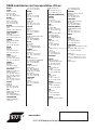
INTERNATIONAL CONTACT INFORMATION ............................................................. REAR COVER
5.07 Preliminary Check of the Control PCB ......................................................................... 5-6
5.08 Check Main Input Rectifier .......................................................................................... 5-7
5.09 DC Bus Voltage Measurement ..................................................................................... 5-8
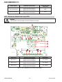
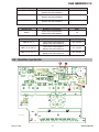
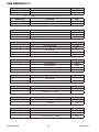
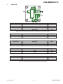
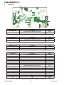
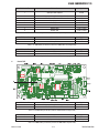
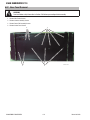
5.10 PCB Connectors .......................................................................................................... 5-9
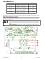
5.11 DIP Switch Settings, Control PCB ............................................................................. 5-16
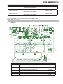
5.12 Calibration ................................................................................................................. 5-17
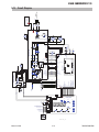
5.13 Circuit Diagram ......................................................................................................... 5-19
5.14 Main Circuit Description ............................................................................................ 5-20
SECTION 6:
DISASSEMBLY PROCEDURE ................................................................................... 6-1
6.01 Safety Precautions for Disassembly ............................................................................ 6-1
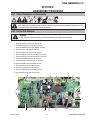
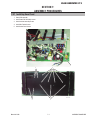
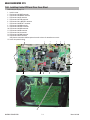
6.02 Control PCB Removal .................................................................................................. 6-1
6.03 Front Panel Assembly Removal ................................................................................... 6-2
6.04 Display PCB Removal .................................................................................................. 6-3
6.05 Back Panel Removal .................................................................................................... 6-4
6.06 Power Switch S1 and Power Cord Removal ................................................................ 6-5
6.07 Base Panel Removal .................................................................................................... 6-6
SECTION 7:
ASSEMBLY PROCEDURES ..................................................................................... 7-1
7.01 Installing Base Panel ................................................................................................... 7-1
7.02 Installing Back Panel ................................................................................................... 7-2
7.03 Installing Front Panel ................................................................................................... 7-3
7.04 Installing Control PCB and Clear Cover Sheet.............................................................. 7-4
7.05 Installing Cover Panel and Door Panel......................................................................... 7-5
SECTION 8:
KEY SPARE PARTS .............................................................................................. 8-1
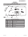
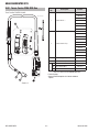
8.01 Tweco WeldSkill 220A MIG Gun (Used until January, 2013 ......................................... 8-1
8.02 Tweco Fusion 220A MIG Gun ..................................................................................... 8-2
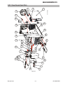
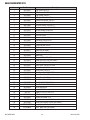
8.03 Power Source Spare Parts ........................................................................................... 8-3
SECTION 9:
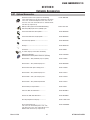
OptionAL Accessories .......................................................................................... 9-1
9.01 Optional Accessories ................................................................................................... 9-1

ESAB FABRICATOR 211i
Manual 0-5450 1-1 SAFETY INSTRUCTIONS AND WARNINGS
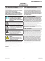
1.0 Safety Precautions
Users of ESAB welding and plasma cutting equipment have the ultimate responsibility for ensuring that anyone who works
on or near the equipment observes all the relevant safety precautions. Safety precautions must meet the requirements
that apply to this type of welding or plasma cutting equipment. The following recommendations should be observed in
addition to the standard regulations that apply to the workplace.
All work must be carried out by trained personnel well acquainted with the operation of the welding or plasma cutting
equipment. Incorrect operation of the equipment may lead to hazardous situations which can result in injury to the
operator and damage to the equipment.
1. Anyone who uses welding or plasma cutting equipment must be familiar with:
- its operation
- location of emergency stops
- its function
- relevant safety precautions
- welding and / or plasma cutting
2. The operator must ensure that:
- no unauthorized person stationed within the working area of the equipment when it is started up.
- no one is unprotected when the arc is struck.
3. The workplace must:
- be suitable for the purpose
- be free from drafts
4. Personal safety equipment:
- Always wear recommended personal safety equipment, such as safety glasses, flame proof
clothing, safety gloves.
- Do not wear loose fitting items, such as scarves, bracelets, rings, etc., which could become
trapped or cause burns.
5. General precautions:
- Make sure the return cable is connected securely.
- Work on high voltage equipment may only be carried out by a qualified electrician.
- Appropriate fire extinguishing equipment must be clearly marked and close at hand.
- Lubrication and maintenance must not be carried out on the equipment during operation.
Dispose of electronic equipment at the recycling facility!
In observance of European Directive 2002/96/EC on Waste Electrical and Electronic Equipment and its
implementation in accordance with national law, electrical and/or electronic equipment that has reached
the end of its life must be disposed of at a recycling facility.
As the person responsible for the equipment, it is your responsibility to obtain information on approved
collection stations.
For further information contact the nearest ESAB dealer.
ESAB can provide you with all necessary cutting protection and accessories.
SECTION 1: SAFETY

ESAB FABRICATOR 211i
SAFETY INSTRUCTIONS AND WARNINGS 1-2 Manual 0-5450
WARNING
Arc welding and cutting can be injurious to yourself and others.
Take precautions when welding and cutting. Ask for your employer's
safety practices which should be based on manufacturers' hazard
data.
ELECTRIC SHOCK - Can kill.
- Install and earth (ground) the welding or plasma cutting unit in accordance with appli-
cable standards.
- Do not touch live electrical parts or electrodes with bare skin, wet gloves or wet cloth-
ing.
- Insulate yourself from earth and the workpiece.
- Ensure your working stance is safe.
FUMES AND GASES - Can be dangerous to health.
- Keep your head out of the fumes.
- Use ventilation, extraction at the arc, or both, to take fumes and gases away from
your breathing zone and the general area.
ARC RAYS - Can injure eyes and burn skin.
- Protect your eyes and body. Use the correct welding / plasma cutting screen and
filter lens and wear protective clothing.
- Protect bystanders with suitable screens or curtains.
FIRE HAZARD
- Sparks (spatter) can cause fire. Make sure therefore that there are no inflammable
materials nearby.
NOISE - Excessive noise can damage hearing.
- Protect your ears. Use earmuffs or other hearing protection.
- Warn bystanders of the risk.
MALFUNCTION - Call for expert assistance in the event of malfunction.
READ AND UNDERSTAND THE INSTRUCTION MANUAL BEFORE INSTALLING OR OPERAT-
ING.
PROTECT YOURSELF AND OTHERS!
WARNING
Do not use the power source for thawing frozen pipes.
CAUTION
Class A equipment is not intended for use in residential locations
where the electrical power is provided by the public low-voltage
supply system. There may be potential difficulties in ensuring
electromagnetic compatibility of class A equipment in those loca-
tions, due to conducted as well as radiated disturbances.
CAUTION
This product is solely intended for metal removal. Any other use
may result in personal injury and / or equipment damage.
CAUTION
Read and understand the instruction manual before
installing or operating.
!

ESAB FABRICATOR 211i
Manual 0-5450 2-1 INTRODUCTION
SECTION 2:
INTRODUCTION
2.02 Equipment Identification
The unit’s identification number (specification or part number),
model, and serial number usually appear on a data tag attached
to the rear panel. Equipment which does not have a data tag
such as torch and cable assemblies are identified only by the
specification or part number printed on loosely attached card or
the shipping container. Record these numbers on the bottom of
page i for future reference.
2.03 Receipt Of Equipment
When you receive the equipment, check it against the invoice
to make sure it is complete and inspect the equipment for pos-
sible damage due to shipping. If there is any damage, notify the
carrier immediately to file a claim. Furnish complete information
concerning damage claims or shipping errors to the location in
your area listed in the inside back cover of this manual.
Include all equipment identification numbers as described above
along with a full description of the parts in error.
Move the equipment to the installation site before un-crating
the unit. Use care to avoid damaging the equipment when using
bars, hammers, etc., to un-crate the unit.
2.04 Description
The ESAB Fabricator 211i is a self contained single phase multi
process welding system that is capable of performing MIG
(GMAW/FCAW), STICK (SMAW) and LIFT TIG (GTAW) welding pro-
cesses. The Power Source is equipped with an integrated wire
feed unit, digital voltage and amperage meters, and a host of
other features in order to fully satisfy the broad operating needs
of the modern welding professional. The Power Source is also
fully compliant to Standard CSA E60974-1-00 and UL 60974.1.
The ESAB Fabricator 211i provides excellent welding perfor-
mance across a broad range of applications when used with
the correct welding consumables and procedures. The follow-
ing instructions detail how to correctly and safely set up the
machine and give guidelines on gaining the best efficiency and
quality from the Power Source. Please read these instructions
thoroughly before using the unit.
2.01 How To Use This Manual
This Owner’s Manual applies to just specification or part num-
bers listed on page i.
To ensure safe operation, read the entire manual, including the
chapter on safety instructions and warnings.
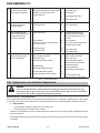
Throughout this manual, the words WARNING, CAUTION,
DANGER, and NOTE may appear. Pay particular attention to the
information provided under these headings. These special an-
notations are easily recognized as follows:
NOTE!
An operation, procedure, or background
information which requires additional
emphasis or is helpful in efficient operation
of the system.
!
CAUTION
A procedure which, if not properly followed,
may cause damage to the equipment.
!
WARNING
A procedure which, if not properly followed,
may cause injury to the operator or others
in the operating area.
WARNING
Gives information regarding possible
electrical shock injury. Warnings will be
enclosed in a box such as this.
!
DANGER
Means immediate hazards which, if not
avoided, will result in immediate, serious
personal injury or loss of life.
Additional copies of this manual may be purchased by contact-
ing ESAB at the address and phone number in your area listed
on back cover of this manual. Include the Owner’s Manual
number and equipment identification numbers.
Electronic copies of this manual can also be downloaded at no
charge in Acrobat PDF format by going to the ESAB web site
listed below
http://www.esab.com

ESAB FABRICATOR 211i
INTRODUCTION 2-2 Manual 0-5450
2.05 Transportation Methods
!
WARNING
FALLING EQUIPMENT can cause serious
personal injury and equipment damage.
!
WARNING
FALLING EQUIPMENT can cause serious
personal injury and equipment damage.
Lift Power Source with handles built into the top of the front and
rear molded panels.
Use handcart or similar device of adequate capacity.
If using a fork lift vehicle, place and secure Power Source on a
proper skid before transporting.
2.06 User Responsibility
This equipment will perform as per the information contained
herein when installed, operated, maintained and repaired in
accordance with the instructions provided. This equipment must
be checked periodically. Defective equipment (including welding
leads) should not be used. Parts that are broken, missing, plainly
worn, distorted or contaminated, should be replaced immediate-
ly. Should such repairs or replacements become necessary, it is
recommended that such repairs be carried out by appropriately
qualified persons approved by ESAB. Advice in this regard can be
obtained by contacting an Accredited ESAB Distributor.
This equipment or any of its parts should not be altered from
standard specification without prior written approval of ESAB.
The user of this equipment shall have the sole responsibil-
ity for any malfunction which results from improper use or
unauthorized modification from standard specification, faulty
maintenance, damage or improper repair by anyone other than
appropriately qualified persons approved by ESAB.
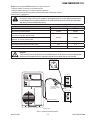
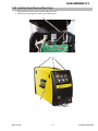
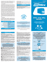
2.07 Fabricator 211i Portable System
Package (Part No. W1004201)
• Fabricator 211i Power Source
• 12 ft. (3.6 m) Tweco Fusion 220 Amp MIG Gun
• Victor Argon Regulator / Flowmeter
• Drive Rolls:
.023"/.030" (0.6/0.8mm) "V" groove,
.023"/.035" (0.6/0.9mm)"V" groove (tted with .035" groove
lined up) ,
.030"/.035" (0.8/0.9mm) "V" knurled for Flux Cored Wire,
• Contact Tips (1 each)
.023"(0.6mm),.030"(0.8mm),
.035"(0.9mm) (tted)
.045"(1.1mm)
• Electrode Holder with 13 ft. (4m) lead
• Work Clamp with 10ft. (3.1m) lead
• Shielding Gas hose assembly
• 15A/20A Adapter Plug from 208/230V AC 50 Amps to 115V
Amps Circuits
• ESAB Cap
• Electrodes
• Large Spring
• Operating Manual
• DVD
A-12923
Figure 2-1: Fabricator 211i System Packaged W1004201

ESAB FABRICATOR 211i
Manual 0-5450 3-1 SAFETY/INSTALLATION
SECTION 3:
SAFETY AND INSTALLATION
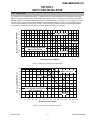
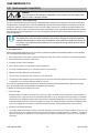
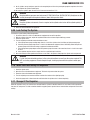
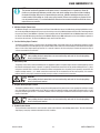
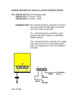
3.01 Duty Cycle
The rated duty cycle of a Welding Power Source, is a statement of the time it may be operated at its rated welding current output
without exceeding the temperature limits of the insulation of the component parts. To explain the 10 minute duty cycle period the
following example is used. Suppose a Welding Power Source is designed to operate at a 20% duty cycle, 210 amperes at 24.5 volts.
This means that it has been designed and built to provide the rated amperage (210A) for 2 minutes, i.e. arc welding time, out of
every 10 minute period (20% of 10 minutes is 2 minutes). During the other 8 minutes of the 10 minute period the Welding Power
Source must idle and allowed to cool. The thermal cut out will operate if the duty cycle is exceeded.
10 20 30 40 50 60 70 80 90 100 110 120 130 140 150 160 170 180 190 200 210 220
FABRICATOR 211i
Welding Current (AMPS)
SAFE OPERATING REGION
(MIG, TIG & STICK)
0
0
10
20
30
40
60
70
50
80
100
90
Duty Cycle (PERCENTAGE)
MIG
STICK / TIG
Art # A-11265
Figure 3-1: Fabricator 211i Duty Cycle on 208/230V AC
Welding Current (AMPS)
Duty Cycle (PERCENTAGE)
Art # A-11274
0
10
20
30
40
50
60
70
80
90
100
0102030405060708090100 110 120 130140 150
FABRICATOR 211i
SAFE OPERATING REGION
(MIG, TIG & STICK)
TIG
STICK
MIG
Figure 3-2: Fabricator 211i Duty Cycle on 115V AC

ESAB FABRICATOR 211i
SAFETY/INSTALLATION 3-2 Manual 0-5450
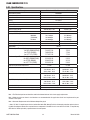
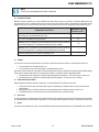
3.02 Specifications
Description Fabricator 211i Multi Process 3 in 1 Welder
Power Source Part No. W1004200
Power Source Dimensions H17.12" x W10.47" x D 24.29" (435mm x 266mm x D617mm)
Power Source Mass 57.3lb (26kg)
Cooling Fan Cooled
Welder Type Multi Process Welding System
Applicable Standard CSA E60974-1-00 / UL60974-1 / IEC 60974-1
Number of Phases Single Phase
Nominal Supply Voltage 208/230 VAC ± 10% 115VAC± 10%
Nominal Supply Frequency 50/60Hz 50/60HZ
Welding Current Range
MIG Mode
STICK Mode
TIG Mode
10-210 Amps
10-200 Amps
10-200 Amps
10-140 Amps
10-110 Amps
10-150 Amps
Wirefeed Speed Range 100 - 600 IPM 100 - 400 IPM
MIG Welding Voltage Range 14.5 - 24.5V DC 14.5 - 19V DC
Nominal OCV 70V DC
Effective Input Current (I1eff)
for MIG (GMAW/FCAW)
for STICK (SMAW)
for LIFT TIG (GTAW)
14.4A/11.2A
16.8A/15.8A
11.7A/11.5A
15.5A
17.8A
17.4A
Maximum Input Current (I1max)
for MIG (GMAW/FCAW)
for STICK (SMAW)
for LIFT TIG (GTAW)
32.2A/25.0A
33.6A/31.6A
23.3A/22.9A
24.5A
30.1A
29.4A
Single Phase Generator Requirement 7.5 KW *3.7 KW
MIG (GMAW/FCAW) Welding Output, 104°F, 10 min. 210A @ 20%,24.5V
122A @ 60%, 20.1V
95A @ 100%, 18.8V
110A @ 45%,19.5V
99A @ 60%, 19.0V
77A @ 100%, 17.9V
STICK (SMAW) Welding Output,1040°F, 10 min. 200A @ 25%,28.0V
130A @ 60%, 25.2V
101A @ 100%, 24.0V
110A @ 35%,24.4V
90A @ 60%, 23.6V
70A @ 100%, 22.8V
TIG (GTAW) Welding Output, 104°F, 10 min. 200A @ 25%,18.0V
130A @ 60%, 15.2V
101A @ 100%, 14.0V
150A @ 35%,16.0V
115A @ 60%, 14.6V
90A @ 100%, 13.6V
Open Circuit Voltage 70 V
Protection Class IP23S
Table 3-1: Fabricator 211i Specifications
Note 1: The Effective Input Current should be used for the determination of cable size & supply requirements.
Note 2: Motor start fuses or thermal circuit breakers are recommended for this application. Check local requirements for your
situation in this regard.
Note 3: Generator Requirements at the Maximum Output Duty Cycle.
* Some 115 VAC, 15 amp/20 amps electrical outlets fitted with GFCI (Ground Fault Circuit Interrupt) protection against nuisance
trip with this equipment due to worn or out of tolerance components in the GFCI. In such cases have the 115 VAC, 15 amp/20 amp
GFCI electrical outlet replaced by a qualified electrical trades person.

ESAB FABRICATOR 211i
Manual 0-5450 3-3 SAFETY/INSTALLATION
NOTE!
The recommended time delay fuse or circuit breaker size for 115V is 30 amp. An individual branch circuit
capable of carrying 30 amperes and protected by fuses or circuit breaker is recommended for this ap-
plication. Fuse size is based on not more than 200 percent of the rated input amperage of the welding
Power Source (Based on Article 630, National Electrical Code)
ESAB continuously strives to produce the best product possible and therefore reserves the right to
change, improve or revise the specifications or design of this or any product without prior notice. Such
updates or changes do not entitle the buyer of equipment previously sold or shipped to the corresponding
changes, updates, improvements or replacement of such items.
The values specified in the table above are optimal values, your values may differ. Individual equipment
may differ from the above specifications due to in part, but not exclusively, to any one or more of the fol-
lowing; variations or changes in manufactured components, installation and conditions and local power
grid supply conditions.
3.03 Environment
This Power Source is designed for use in environments with increased hazard of electric shock. Additional safety precautions may
be required when using unit in an environment with increased hazard of electric shock. Please refer to relevant local standards for
further information prior to using in such areas.
A. Examples of environments with increased hazard of electric shock are:
1. In locations in which freedom of movement is restricted, so that the operator is forced to perform the work in a cramped
(kneeling, sitting or lying) position with physical contact with conductive parts.
2. In locations which are fully or partially limited by conductive elements, and in which there is a high risk of unavoidable or
accidental contact by the operator.
3. In wet or damp hot locations where humidity or perspiration considerably reduces the skin resistance of the human body
and the insulation properties of accessories.
B. Environments with increased hazard of electric shock do not include places where electrically conductive parts in the near
vicinity of the operator, which can cause increased hazard, have been insulated.
3.04 Location
Be sure to locate the welder according to the following guidelines:
A. In areas, free from moisture and dust.
B. Ambient temperature between 14° F (0° C) to 104° F (40° C).
C. In areas, free from oil, steam and corrosive gases.
D. In areas, not subjected to abnormal vibration or shock.
E. In areas, not exposed to direct sunlight or rain.
F. Place at a distance of 12" (305mm) or more from walls or similar that could restrict natural air flow for cooling.
G. The enclosure design of this Power Source meets the requirements of IP23S as outlined in EN 60529. This provides adequate
protection against solid objects (greater than 1/2", 12mm) and direct protection from vertical drops. Under no circumstances
should the Power Source be operated or connected in a micro environment that will exceed the stated conditions. For further
information please refer to EN 60529.
H. Precautions must be taken against the power source toppling over. The power source must be located on a suitable horizontal
surface in the upright position when in use.
WARNING
This equipment should be electrically connected by a qualified electrician.

ESAB FABRICATOR 211i
SAFETY/INSTALLATION 3-4 Manual 0-5450
3.05 Ventilation
!
WARNING
Since the inhalation of welding fumes can be harmful, ensure that the welding area is effec-
tively ventilated.
3.06 Electricity Supply
!
CAUTION
The Electricity Supply voltage should be within 208/230V AC ± 10% or 115 V AC ± 10%. Too low a supply
voltage may cause poor welding performance in STICK mode such as the arc snuffing out during welding.
Too high a supply voltage will cause components to overheat and possibly fail. The Welding power Source
must be:
• Correctly installed, if necessary, by a qualied electrician.
• Correctly earthed (electrically) in accordance with local regulations.
• Connected to the correct size power point and fuse as per the Specications on page 3-2.
WARNING
The Fabricator 211i must be electrically connected by a qualified electrical trades-person. Damage to the
PCA (Power Control Assembly) could occur if 265 VAC or higher is applied to the Primary Power Cable
WARNING
ELECTRIC SHOCK can kill; SIGNIFICANT DC VOLTAGE is present after removal of input power. DO
NOT TOUCH live electrical parts.
SHUT DOWN welding power source, disconnect input power employing lockout/tagging procedures. Lock-out/tagging procedures
consist of padlocking line disconnect switch in open position, removing fuses from fuse box, or shutting OFF and red-tagging circuit
breaker or other disconnecting device.
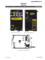
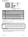
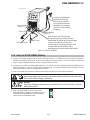
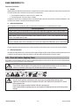
Power Cords Included With Power Supply
Attached to the power supply is an input power cord with a 208/230Volt 50 Amp NEMA 6-50 P for plug. Supplied adapter allow for
connection of the power supply input cable plug to 115 V input power.
Art# A-11275
Figure 3-3: 115 VAC Adapter
Electrical Input Requirements
Operate the welding power source from a single-phase 50/60 Hz, AC power supply. The input voltage must match one of the electri-
cal input voltages shown on the input data label on the unit nameplate. Contact the local electric utility for information about the type
of electrical service available, how proper connections should be made, and inspection required. The line disconnect switch provides
a safe and convenient means to completely remove all electrical power from the welding power supply whenever necessary to
inspect or service the unit. The Welding Power Source must be:
Do not connect in input (WHITE or BLACK) conductor to the ground terminal.

ESAB FABRICATOR 211i
Manual 0-5450 3-5 SAFETY/INSTALLATION
Do not connect the ground (GREEN) conductor to an input line terminal.
• Correctly installed, if necessary, by a qualied electrician.
• Correctly earthed (electrically) in accordance with local regulations.
• Connected to the correct size power point, fuse and primary supply lead based on Table 3-2.
Refer to Figure 3-3 and Table 3-2.
WARNING
An electrical shock or fire hazard is probable if the following electrical service guide recommendations
are not followed. These recommendations are for a dedicated branch circuit sized for the rated output
and duty cycle of the welding Power Source.
50 / 60 Hz Single Phase Supply
Supply Voltage 208/230V AC 115V AC
Input Current at Maximum Output 32 Amps 30 Amps
Maximum Recommended Fuse* or Circuit Breaker Rating * Time
Delay Fuse, UL class RK5. Refer to UL248
50 Amps
50 Amps
30 Amps
30 Amps
Maximum Recommended Fuse^ or Circuit Breaker Rating ^Normal
Operating , UL class K5. Refer to UL248
Minimum Recommended Cord Size 12 AWG 12 AWG
Maximum Recommended Extension Cord Length 50 ft 25 ft
Minimum Recommended Grounding Conductor Size 12 AWG 12AWG
Table 3-2: Electrical Service Guide
!
CAUTION
The time-delay fuses or circuit breaker of an individual branch circuit may have nuisance tripping when
welding with this product due to the amperage rating of the time-delay fuses or circuit breaker.
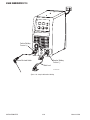
Art# A-11240
Primary Power Cable
115
115
V,
V,
20A,1Ø
15A,1Ø
208/230V, 50A,1Ø
The Adapter enable
connection to all these
power outlets
115 VAC Adapter
Figure 3-4: Electrical Input Connections

ESAB FABRICATOR 211i
SAFETY/INSTALLATION 3-6 Manual 0-5450
3.07 Electromagnetic Compatibility
!
WARNING
Extra precautions for Electromagnetic Compatibility may be required when this Welding Power
Source is used in a domestic situation.
A. Installation and Use - Users Responsibility
The user is responsible for installing and using the welding equipment according to the manufacturer’s instructions. If electromag-
netic disturbances are detected then it shall be the responsibility of the user of the welding equipment to resolve the situation with
the technical assistance of the manufacturer. In some cases this remedial action may be as simple as earthing the welding circuit,
see NOTE below. In other cases it could involve constructing an electromagnetic screen enclosing the Welding Power Source and the
work, complete with associated input filters. In all cases, electromagnetic disturbances shall be reduced to the point where they are
no longer Troublesome.
NOTE!
The welding circuit may or may not be earthed for safety reasons. Changing the earthing arrangements
should only be authorized by a person who is competent to assess whether the changes will increase the
risk of injury, e.g. by allowing parallel welding current return paths which may damage the earth circuits
of other equipment.
B. Assessment of Area
Before installing welding equipment, the user shall make an assessment of potential electromagnetic problems in the surrounding
area. The following shall be taken into account.
1. Other supply cables, control cables, signaling and telephone cables; above, below and adjacent to the welding equipment.
2. Radio and television transmitters and receivers.
3. Computer and other control equipment.
4. Safety critical equipment, e.g. guarding of industrial equipment.
5. The health of people around, e.g. the use of pace-makers and hearing aids.
6. Equipment used for calibration and measurement.
7. The time of day that welding or other activities are to be carried out.
8. The immunity of other equipment in the environment: the user shall ensure that other equipment being used in the environment
is compatible: this may require additional protection measures.
The size of the surrounding area to be considered will depend on the structure of the building and other activities that are taking
place. The surrounding area may extend beyond the boundaries of the premises.
C. Methods of Reducing Electromagnetic Emissions
1. Electricity Supply
Welding equipment should be connected to the Electricity Supply according to the manufacturer’s recommendations. If
interference occurs, it may be necessary to take additional precautions such as filtering of the Electricity Supply. Consideration
should be given to shielding the supply cable of permanently installed welding equipment in metallic conduit or equivalent.
Shielding should be electrically continuous throughout its length. The shielding should be connected to the Welding Power
Source so that good electrical contact is maintained between the conduit and the Welding Power Source enclosure.
2. Maintenance of Welding Equipment
The welding equipment should be routinely maintained according to the manufacturer’s recommendations. All access and
service doors and covers should be closed and properly fastened when the welding equipment is in operation. The welding
equipment should not be modified in any way except for those changes and adjustments covered in the manufacturer’s
instructions.

ESAB FABRICATOR 211i
Manual 0-5450 3-7 SAFETY/INSTALLATION
3. Welding Cables
The welding cables should be kept as short as possible and should be positioned close together but never coiled and running
at or close to the floor level.
4. Equipotential Bonding
Bonding of all metallic components in the welding installation and adjacent to it should be considered. However, metallic
components bonded to the work piece will increase the risk that the operator could receive a shock by touching the metallic
components and the electrode at the same time. The operator should be insulated from all such bonded metallic components.
5. Earthing/grounding of the Work Piece
Where the work piece is not bonded to earth for electrical safety, nor connected to earth because of its size and position, e.g.
ship’s hull or building steelwork, a connection bonding the work piece to earth may reduce emissions in some, but not all
instances. Care should be taken to prevent the earthing of the work piece increasing the risk of injury to users, or damage
to other electrical equipment. Where necessary, the connection of the work piece to earth should be made by direct con-
nection to the work piece, but in some countries where direct connection is not permitted, the bonding should be achieved
by suitable capacitance, selected according to national regulations.
6. Screening and Shielding
Selective screening and shielding of other cables and equipment in the surrounding area may alleviate problems of interference.
Screening the entire welding installation may be considered for special applications.
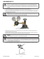
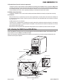
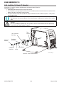
3.08 Victor Regulator
Pressure regulator (Figure 3-5) attached to the cylinder valve reduce high cylinder pressures to suitable low working pressures for
welding, cutting, and other applications.
A-09414_AC
Figure 3-5: Victor CS Regulator
!
WARNING
Use the regulator for the gas and pressure for which it is designed. NEVER alter a regulator for use with
any other gas.
NOTE!
Regulators purchased with open 1/8”, 1/4”, 3/8”, or 1/2” NPT ports must be assembled to their intended
system.
1. Note the maximum inlet pressure stamped on the regulator. DO NOT attach the regulator to a system that has a higher pres-
sure than the maximum rated pressure stamped on the regulator.
2. The regulator body will be stamped “IN” or “HP” at the inlet port. Attach the inlet port to the system supply pressure connec-
tion.
3. If gauges are to be attached to the regulator and the regu lator is stamped and listed by a third party (i.e. “UL” or “ETL”). The
following requirements must be met:
a) Inlet gauges over 1000 PSIG (6.87 mPa) shall conform with the requirements of UL 404, “Indicating Pressure Gauges for
Compressed Gas Service.”
b) Low pressure gauges must be UL recognized for the class of regulator they are being used on according to UL252A.

ESAB FABRICATOR 211i
SAFETY/INSTALLATION 3-8 Manual 0-5450
!
WARNING
DO NOT use a regulator that delivers pressure exceeding the pressure rating of the downstream equip-
ment unless pro visions are made to prevent over-pressurization (i.e. system relief valve). Make sure the
pressure rating of the down stream equipment is compatible with the maximum delivery pressure of the
regulator.
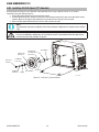
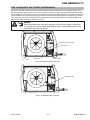
4. Be sure that the regulator has the correct pressure rating and gas service for the cylinder used.
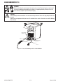
5. Carefully inspect the regulator for damaged threads, dirt, dust, grease, oil, or other flammable substances. Remove dust and
dirt with a clean cloth. Be sure the inlet swivel filter is clean and in place. Attach the regulator (Figure 3-6) to the cylinder
valve. Tighten securely with a wrench.
!
WARNING
DO NOT attach or use the regulator if oil, grease, flamma ble substances or damage is present! Have a
qualified repair technician clean the regulator or repair any damage.
A-09845_AB
Figure 3-6: Regulator to Cylinder Valve
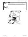
6. Before opening the cylinder valve, turn the regulator adjusting screw counterclockwise until there is no pressure on the
adjusting spring and the screw turns freely.
7. Relief Valve (where provided): The relief valve is designed to protect the low pressure side of the regulator from high pres-
sures. Relief valves are not intended to protect down stream equipment from high pressures.
!
WARNING
DO NOT tamper with the relief valve or remove it from the regulator.
!
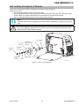
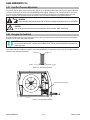
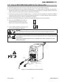
WARNING
Stand to the side of the cylinder opposite the regulator when opening the cylinder valve. Keep the cylinder
valve between you and the regulator. For your safety, NEVER STAND IN FRONT OF OR BEHIND A REGULA-
TOR WHEN OPENING THE CYLINDER VALVE!
8. Slowly and carefully open the cylinder valve (Figure 3-7) until the maximum pressure shows on the high pressure gauge.
Art # A-09828
Figure 3-7: Open Cylinder Valve

ESAB FABRICATOR 211i
Manual 0-5450 3-9 SAFETY/INSTALLATION
9. On all cylinders, except acetylene, open the valve completely to seal the valve packing. On gaugeless regulators, the indica-
tor will register the cylinder contents open.
10. On acetylene cylinders, open the valve 3/4 of a turn and no more than 1-1/2.
!
WARNING
Acetylene delivery pressure must not exceed 15 PSIG (103 kPa) or 30 PSIG (207 kPa). Acetylene can dis-
sociate (decompose with explosive violence) above these pressure limits.
!
CAUTION
Keep the cylinder valve wrench, if one is required, on the cylinder valve to turn off the cylinder quickly, if
necessary.
11. Attach the desired downstream equipment.
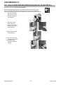
3.09 Leak Testing The System
Leak test the system before putting into operation.
1. Be sure that there is a valve in the downstream equipment to turn off the gas flow.
2. With the cylinder valve open, adjust the regulator to deliver the maximum required delivery pressure.
3. Close the cylinder valve.
4. Turn the adjusting screw/knob counterclockwise one turn.
a) If the high-pressure gauge reading drops, there is a leak in the cylinder valve, inlet fitting, or high-pressure gauge.
b) If the low-pressure gauge drops, there is a leak in the down stream equipment, hose, hose fitting, outlet fitting or low-
pressure gauge. Check for leaks using an approved leak detector solution.
c) If the high-pressure gauge drops and the low-pressure gauge increases at the same time, there is a leak in the regula-
tor seat.
d) If the regulator requires service or repair, take it to a qualified repair technician.
5. Once leak testing has been performed and there are no leaks in the system, slowly open the cylinder valve and proceed.
!
WARNING
If a leak has been detected anywhere in the system, dis continue use and have the system repaired. DO
NOT use leaking equipment. Do not attempt to repair a leaking system while the system is under pres-
sure.
3.10 When You Finish Using The Regulator
1. Close the cylinder valve.
2. Open the valve on the downstream equipment. This drains all pressure from the system.
3. Close the valve on the downstream equipment.
4. Turn the adjusting screw counterclockwise to release the ten sion on the adjusting spring.
5. Check the gauges after a few minutes for verification that the cylinder valve is closed completely.
3.11 Storage Of The Regulator
When the regulator is not in use and has been removed from the cylinder, it should be stored in an area where it will be pro tected
from dust, oil, and grease. The inlet and outlet should be capped to protect against internal contamination and prevent insects from
nesting.

ESAB FABRICATOR 211i
SAFETY/INSTALLATION 3-10 Manual 0-5450
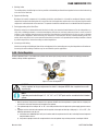
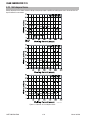
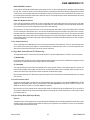
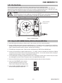
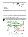
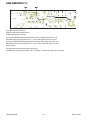
3.12 Volt-Ampere Curves
Voltage-Amperage Curves shows maximum voltage and amperage output capabilities of welding power source. Curves of other set-
tings fall between curves shown.
Art # A-11297
Figure 3-8: Fabricator 211i Volt-Ampere Curves
Page is loading ...
Page is loading ...
Page is loading ...
Page is loading ...
Page is loading ...
Page is loading ...
Page is loading ...
Page is loading ...
Page is loading ...
Page is loading ...
Page is loading ...
Page is loading ...
Page is loading ...
Page is loading ...
Page is loading ...
Page is loading ...
Page is loading ...
Page is loading ...
Page is loading ...
Page is loading ...
Page is loading ...
Page is loading ...
Page is loading ...
Page is loading ...
Page is loading ...
Page is loading ...
Page is loading ...
Page is loading ...
Page is loading ...
Page is loading ...
Page is loading ...
Page is loading ...
Page is loading ...
Page is loading ...
Page is loading ...
Page is loading ...
Page is loading ...
Page is loading ...
Page is loading ...
Page is loading ...
Page is loading ...
Page is loading ...
Page is loading ...
Page is loading ...
Page is loading ...
Page is loading ...
Page is loading ...
Page is loading ...
Page is loading ...
Page is loading ...
Page is loading ...
Page is loading ...
Page is loading ...
Page is loading ...
Page is loading ...
Page is loading ...
Page is loading ...
Page is loading ...
Page is loading ...
Page is loading ...
-
 1
1
-
 2
2
-
 3
3
-
 4
4
-
 5
5
-
 6
6
-
 7
7
-
 8
8
-
 9
9
-
 10
10
-
 11
11
-
 12
12
-
 13
13
-
 14
14
-
 15
15
-
 16
16
-
 17
17
-
 18
18
-
 19
19
-
 20
20
-
 21
21
-
 22
22
-
 23
23
-
 24
24
-
 25
25
-
 26
26
-
 27
27
-
 28
28
-
 29
29
-
 30
30
-
 31
31
-
 32
32
-
 33
33
-
 34
34
-
 35
35
-
 36
36
-
 37
37
-
 38
38
-
 39
39
-
 40
40
-
 41
41
-
 42
42
-
 43
43
-
 44
44
-
 45
45
-
 46
46
-
 47
47
-
 48
48
-
 49
49
-
 50
50
-
 51
51
-
 52
52
-
 53
53
-
 54
54
-
 55
55
-
 56
56
-
 57
57
-
 58
58
-
 59
59
-
 60
60
-
 61
61
-
 62
62
-
 63
63
-
 64
64
-
 65
65
-
 66
66
-
 67
67
-
 68
68
-
 69
69
-
 70
70
-
 71
71
-
 72
72
-
 73
73
-
 74
74
-
 75
75
-
 76
76
-
 77
77
-
 78
78
-
 79
79
-
 80
80


ESAB ESAB Fabricator® 211i 3-IN-1 Multi Process Welding Systems User manual
- Category
- Welding System
- Type
- User manual
Ask a question and I''ll find the answer in the document
Finding information in a document is now easier with AI
Related papers
-
ESAB FABRICATOR® 211i 3-IN-1 Multi Process Welding Systems User manual
-
-
-
-
-
-
-
ESAB ESAB Fabricator® 252i 3-IN-1 Multi Process Welding Systems User manual
-
-
Other documents
-
MURPHY DOOR 1689351746 Owner's manual
-
Western Speed Control Installation guide
-
 Thermal Arc 211i Operating instructions
-
 HSS Hire HW055/OI Operating & Safety Manual
-
 OMIX 19101.04 Installation guide
-
 OMIX 19101.03 Installation guide
-
Rockville RXC20D Owner's manual
-
-
 Svarog ARC 160-PFC User manual
-
 Thermal Arc 186 DC Setup Manual


