Page is loading ...

1
2
3
4
FOLD LINE ‘A’
FOLD LINE ‘B’
5
Quick Start Guide
LIFT TIG & HF or STICK WELDING
140 AC/DC Setup Outline:
1) Unpack
2) SETUP Gas Regulator
3) SETUP Power Source
4) SETUP for LIFT TIG or HF TIG
5) SETUP for STICK
FIREPOWER 140AC/DC
Publication Date: Augest 29, 2014Revision: AAQuick Start Guide Number: 0-5356
W
eld
Curren
t
A
MODE
2T
4T
TRIGGE
R
22 ga.
(0.8 mm)
18 ga.
(1.2 mm)
16 ga
.
(1.6 mm)
1/8"
(3.2 mm)
3/16"
(4.7 mm)
1/4"
(6.4 mm)
PROCESS
LIFT TIG
HF TIG
STIC
K
T
I
G
AC
(A
l
um
in
u
m
)
Amps
D
C
(
Mi
l
d &
Sta
i
nl
e
s
s
S
teel
)
2
5
4
0
65
1
2
5
1
4
0
S
T
IC
K
7
0
90
Amps
1. 140 AC/DC Power supply and
Accessories
A) Carefully unpack the 140 AC/DC.
B) Conrm that all items listed to the right are present.
• FIREPOWER 140 AC/DC Inverter Power Source
• Tweco 140 Amp Electrode Holder with 13ft (4m) Lead
• Tweco 140 Amp Work Clamp with 10ft (3m) Lead
• Controls & Accessory
• AC Plug
• Firepower Argon Flow Gauge & 12.5 ft (3.8m) Hose
• Shoulder Strap
• Operating Manual, Quick Start Guide, & CD
2. SETUP Gas Regulator
A) Attach the Argon regulator to the cylinder valve and tighten securely with a wrench.
B) Purge the regulator by SLIGHTLY opening the cylinder valve for 3-to-5 seconds
and then close.
C) Connect the 140 gas hose to the gas outlet on the regulator. Wrench tight 1/4 turn.
D) Slowly and carefully open the cylinder valve until the maximum pressure
shows on the High-Pressure gauge.
E) Adjust regulator knob on the Low-Pressure gauge so the needle is
in the TIG, (Blue Section).
Cylinder Valve
Regulator
High-PressureLow-Pressure
Gas Outlet
Tighten with
wrench
Regulator
Adjusting
Knob
3. SETUP Power Source
The 140 AC/DC comes with a 125 Volt 20 Amp 2 pole 3 wire input power cord attached to the back panel.
A) Plug the unit into an 50 / 60 Hz Single Phase 115V power source rated for 20 amps.
B) Do NOT turn the unit ON at this time.
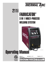
4. SETUP for LIFT TIG or HF TIG
A) Select Lift TIG or HF TIG mode with the process selection control.
B) Connect the TIG Torch to the negative welding terminal (-). Welding current ows
from the power source via 50 mm Dinse terminals.
C) Connect the work lead to the positive welding terminal (+).
D) Connect the TIG torch trigger switch via the 8 pin socket located on the front
of the power source. The TIG torch requires a trigger switch to operate in Lift TIG or HF TIG Mode.
E) Connect the gas hose from the TIG torch to the gas OUTLET on the front of the 140 AC/DC.
8
Negative
Welding
Terminal (-)
Positive
Welding
Terminal (+)
8 Pin
Control Socket
TIG Torch
A
MODE
2T
4T
TRIGGER
22 ga.
(0.8 mm)
18 ga.
(1.2 mm)
16 ga.
(1.6 mm)
1/8"
(3.2 mm)
3/16"
(4.7 mm)
1/4"
(6.4 mm)
PROCESS
LIFT TIG
HF TIG
STICK
TIG
AC (Aluminum)
Amps
DC
(Mild & Stainless Steel)
25 40 65 125 140
STICK
70 90
Amps
Work Lead
Recommended Settings Chart
(For your reference this chart is also on the inside side panel.)
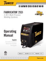
5. SETUP for STICK
A) Connect the Electrode Holder lead to the positive welding terminal (+).
B) Connect the work lead to the negative welding terminal (-).
C) Select STICK mode with the process selection control.
Recommended Settings Chart
(For your reference this chart is also on the inside side panel.)
8
Negative
Welding
Terminal (-)
Positive
Welding
Terminal (+)
Electrode Holder
Work Lead
A
MODE
2T
4T
TRIGGER
22 ga.
(0.8 mm)
18 ga.
(1.2 mm)
16 ga.
(1.6 mm)
1/8"
(3.2 mm)
3/16"
(4.7 mm)
1/4"
(6.4 mm)
PROCESS
LIFT TIG
HF TIG
STICK
TIG
AC
(Aluminum)
Amps
DC
(Mild & Stainless Steel)
25 40 65 125 140
STICK
70 90
Amps
© 2014 Victor Technologies International, Inc. www.victortechnologies.com Printed in China
U.S. Customer Care: 800-426-1888 / fax 800-535-0557 • Canada Customer Care: 905-827-4515 / fax 800-588-1714
International Customer Care: 940-381-1212 / fax 940-483-8178 • CIGWELD Customer Care: 1 300-654-674 / fax 61-3-9474-7391
INNOVATION TO SHAPE THE WORLD
™
TECHNOLOGIES
™
Copyright © 2014 Victor Technologies, Inc. All rights reserved.
Reproduction of this work, in whole or in part, without written permission of
the publisher is prohibited.
The publisher does not assume and hereby disclaims any liability to any
party for any loss or damage caused by any error or omission in this Quick Start Guide,
whether such error results from negligence, accident, or any other cause.
QRC
Read and understand this entire guide, the Operating Manual and your
employer’s safety practices before installing, operating, or servicing the equipment.
While the information contained in this guide represents the Manufacturer’s
best judgment, the Manufacturer assumes no liability for its use.
Refer to the 140 AC/DC Operation Manual for detailed safety and operation instructions.
WARNINGS and CAUTIONS
• ELECTRIC SHOCK can kill. Touching live electrical parts can cause fatal shocks or severe burns.
• Incorrectly installed or improperly grounded equipment is a hazard.
• STICK Electrode is electrically live as soon as it is in the Electrode Holder.
• Never stand in front of or behind a regulator when opening the cylinder valve!
• DO NOT attach or use the regulator if oil, grease, ammable substances, or damage is present!
Stand to the side of the cylinder opposite the regulator when opening the cylinder valve.
Keep the cylinder valve between you and the regulator.
• NEVER use a compressed gas cylinder without a pressure reducing regulator attached to the cylinder valve.
• Always use a regulator designed for the type gas used.
• Maintain an adequate distance of the wire from metal objects to avoid burnbacks to conduit or conductor tube.
• Always wear a welding helmet tted with a proper shade of lter (see Safety Standards in the Operation manual) to
protect your face and eyes when welding or watching, and safety equipment when welding.
SAFETY STATEMENTS
/