Page is loading ...

TEMPSTAR HH-E
INSTALLATION, OPERATION,
AND SERVICE MANUAL
TempStar
®
HH-E Manual • 07610-002-23-32-AD
TEMPSTAR
®
SERIES DOOR-TYPE DISHMACHINES
®

MANUFACTURER'S LIMITED WARRANTY
(APPLICABLE ONLY IN THE UNITED STATES AND CANADA)
WARRANTY REGISTRATION:
To register your Jackson Dishmachine’s warranty go to www.jacksonwws-warranty.com or call 1-888-800-5672. Failure
to register the Dishmachine will void the warranty.
ONE YEAR LIMITED PARTS AND LABOR WARRANTY
For a period of one (1) year from date of original installation of a new Jackson Dishmachine (but in no event to exceed
eighteen (18) months from date of shipment from Jackson’s factory), Jackson WWS, Inc. (Jackson) will repair or replace,
at its discretion, any original part that proves defective in materials or workmanship at the time the Dishmachine was
purchased; provided that (i) the Dishmachine has not been altered, (ii) the Dishmachine has been properly installed,
maintained, and operated under normal use conditions and in accordance with the applicable installation, operation and
service manual available on the Jackson website, and (iii) a warranty claim is reported to a Jackson Authorized Service
Agency within the warranty period. This warranty includes replacement with Jackson specied genuine replacement parts,
purchased directly from a Jackson Authorized Parts Distributor or Service Agency. Use of generic replacement parts may
create a hazard and shall void this warranty.
THIS WARRANTY DOES NOT APPLY OUTSIDE THE UNITED STATES AND CANADA.
Jackson will pay the labor to repair or replace a defective original part as a part of the warranty, provided that a Jackson
Authorized Service Agency performs the labor. Any repair or replacement work by anyone other than a Jackson
Authorized Service Agency is the sole responsibility of the purchaser. Labor coverage is limited to regular hourly rates;
Jackson will not pay overtime premiums or emergency service charges.
Accessory components (such as table limit switches, pressure regulators, and drain water tempering kits) that are not
installed by Jackson at the factory and are shipped with the Dishmachine carry only a (1) one year parts warranty.
Labor to repair or replace these components is not included in the warranty or covered by Jackson. Booster heaters not
manufactured by Jackson are not covered by this warranty, but are warranted by their respective manufacturers.
This warranty is void if any defect or failure is a direct result from shipping, handling, re, water, accident, alteration,
modication, misuse, abuse, ood, acts of God, burglary, casualty, attempted repair by unauthorized persons, use of
replacement parts not authorized by Jackson, improper installation, installation not in accordance with local electrical and
plumbing codes, if the serial number has been removed or altered, if the Dishmachine is used for any purpose other than
originally intended, or if the equipment is installed for residential use.
Jackson does not authorize any other entity or person, including, without limitation, any entity or person who deals
in Jackson’s Dishmachines, to change this warranty or create any other obligation in connection with Jackson’s
Dishmachines.
TRAVEL LIMITATIONS:
Jackson limits warranty travel time to the customer site within 50 miles of the Jackson authorized service agents ofce
and during regular business hours. Jackson will not pay for travel time and mileage that exceeds these limits, or any fees
such as those for air or boat travel without prior authorization.
REPLACEMENT PARTS WARRANTY:
For a period of (90) ninety days from the date of installation by a Jackson Authorized Service Agency (but in no event to
exceed (180) one-hundred-eighty days from the date of purchase from a Jackson Authorized Parts Distributor or Service
Agency), Jackson will repair or replace, at its discretion, any Jackson genuine replacement parts that prove defective
in materials or workmanship at the time the replacement parts were installed. This warranty does not include paying
the labor to repair or replace the replacement part. This warranty is subject to all conditions, exclusions and limitations
applicable to the Dishmachine.

MANUFACTURER'S LIMITED WARRANTY (CONT.)
(APPLICABLE ONLY IN THE UNITED STATES AND CANADA)
PRODUCT CHANGES:
Jackson reserves the right to make changes in design and specication of any component of the Dishmachine as
engineering or necessity requires.
DISCLAIMER OF WARRANTIES:
THERE ARE NO WARRANTIES, EXPRESSED OR IMPLIED, INCLUDING, WITHOUT LIMITATION, ANY IMPLIED
WARRANTY OF FITNESS FOR A PARTICULAR PURPOSE OR MERCHANTABILITY, THAT ARE NOT SET FORTH
HEREIN, OR THAT EXTEND BEYOND THE DURATION HEREOF.
LIMITATION OF REMEDIES AND LIABILITIES:
YOUR SOLE AND EXCLUSIVE REMEDY UNDER THIS LIMITED WARRANTY SHALL BE PRODUCT REPAIR OR
REPLACEMENT AS PROVIDED HEREIN.
UNDER NO CIRCUMSTANCES WILL JACKSON BE LIABLE FOR ANY INCIDENTAL OR CONSEQUENTIAL
DAMAGES, OR FOR DAMAGES IN THE NATURE OF PENALTIES. JACKSON’S LIABILITY ON ANY CLAIM OF ANY
KIND WITH RESPECT TO THE GOODS OR SERVICES COVERED HEREUNDER SHALL IN NO CASE EXCEED THE
PRICE OF THE GOODS OR SERVICES OR PART THEREOF WHICH GIVES RISE TO THE CLAIM.
ITEMS NOT COVERED:
THIS WARRANTY DOES NOT COVER (1) ADJUSTMENTS INCLUDING, BUT NOT LIMITED TO, TIMER CAMS,
THERMOSTATS, DOORS, TANK HEATER ADJUSTMENTS OR CLUTCHES; (2) AIR FREIGHT OR OVERNIGHT
FREIGHT; (3) ANY AMOUNT EXCEEDING ORIGINAL PURCHASE PRICE; (4) CLEANING OF DRAIN VALVES,
GAS LINES, RINSE/WASH NOZZLES, STRAINERS, SCREENS, OR SPRAY PIPES; (5) CLEANING OR DELIMING
OF THE DISHMACHINE OR ANY COMPONENT INCLUDING, BUT NOT LIMITED TO, WASH ARMS, RINSE
ARMS AND STRAINERS; (6) CONDITIONS CAUSED BY THE USE OF INCORRECT (NON-COMMERCIAL)
GRADE DETERGENTS; (7) CORROSION FROM CHEMICALS DISPENSED IN EXCESS OF RECOMMENDED
CONCENTRATIONS; (8) COSMETIC DAMAGE, INCLUDING BUT NOT LIMITED TO, SCRATCHES, DENTS, CHIPS,
AND OTHER DAMAGE TO THE DISHMACHINE FINISHES, UNLESS SUCH DAMAGE RESULTS FROM DEFECTS IN
MATERIALS AND WORKMANSHIP AND IS REPORTED TO JACKSON WITHIN (30) THIRTY DAYS FROM THE DATE
OF INSTALLATION; (9) DAMAGE CAUSED BY LABOR DISPUTE; (10) DAMAGES RESULTING FROM IMPROPER
CONNECTION TO UTILITY SERVICE; (11) DAMAGES RESULTING FROM WATER CONDITIONS, INADEQUATE OR
EXCESSIVE WATER PRESSURE, ACCIDENTS, ALTERATIONS, IMPROPER USE, ABUSE, HANDLING, OVERLOADS,
TAMPERING, IMPROPER INSTALLATION OR FAILURE TO FOLLOW MAINTENANCE AND OPERATING
PROCEDURES; (12) DISCOLORATION, RUST OR OXIDATION OF SURFACES RESULTING FROM CAUSTIC
OR CORROSIVE ENVIRONMENTS, INCLUDING, BUT NOT LIMITED TO, HIGH SALT CONCENTRATIONS, HIGH
MOISTURE OR HUMIDITY, OR EXPOSURE TO CHEMICALS; (13) ELECTRIC BOOSTERS, FEED LINES, FLEX HOSE,
FUSES, GARBAGE DISPOSALS, OR GAS PILOTS; (14) EXCESSIVE LIME, MINERAL, OR ALKALINE BUILDUP; (15)
EXPENSES DUE TO DISCONNECTION, DELIVERY, RETURN AND REINSTALLATION; (16) FAILURE OF ELECTRICAL
COMPONENTS DUE TO CONNECTION OF CHEMICAL DISPENSING EQUIPMENT INSTALLED BY OTHERS; (17)
FAILURE OF FACILITY WATER HEATER TO MAKE TEMPERATURE; (18) FAILURE TO MAINTAIN WATER HARDNESS
BETWEEN .25 AND 2.0 GRAINS, PH BETWEEN 7.0 AND 8.5 AND TOTAL DISSOLVED SOLIDS BELOW 250 PPM; (19)
FAILURE TO COMPLY WITH LOCAL ELECTRICAL BUILDING CODES; (20) LEAKS OR DAMAGE RESULTING FROM
SUCH LEAKS CAUSED BY THE INSTALLER, INCLUDING THOSE AT MACHINE TABLE CONNECTIONS, OR BY
CONNECTION OF CHEMICAL DISPENSING EQUIPMENT INSTALLED BY OTHERS; (21) OPENING OR CLOSING OF
UTILITY SUPPLY VALVES OR SWITCHING OF ELECTRICAL SUPPLY CURRENT; (22) PERFORMANCE OF REGULAR
MAINTENANCE AND CLEANING AS OUTLINED IN THE OPERATOR’S GUIDE; (23) REMOVAL OR REINSTALLATION
OF INACCESSIBLE DISHMACHINES OR BUILT-IN FIXTURES THAT INTERFERE WITH SERVICING, REMOVAL OR
REPLACEMENT OF THE DISHMACHINE; (24) REPLACEMENT WEAR ITEMS INCLUDING, BUT NOT LIMITED TO,
CURTAINS, DRAIN BALLS, DOOR GUIDES, GASKETS, O-RINGS, SEALS, SQUEEZE TUBES, AND BEARINGS; (25)
RESIDENTIAL USE; (26) USE WITH UTILITY SERVICE OTHER THAN THAT DESIGNATED ON THE RATING PLATE.

Revision
Letter
Revision
Date
Made by
Applicable
ECN
Details
F 6-1-04 MAW N/A Change to new layout.
G 1-5-05 MAW N/A
Corrected amerate ratings, changed to thermostat bracket
05700-011-81-64, changed thermostat 05930-121-71-29 to
thermostat kit 06401-140-00-32, updated drawing for false panel
installation, and added SDI override instructions.
H 1-17-06 MAW 7609 Added universal timer, parts, and schematics.
I 7-6-06 MAW
7713, 7571,
7493, 7553,
7411, 7422,
7231
Updated specication & dimension pages.
Updated drain quench assembly.
Replaced door switch 05930-003-02-20 with 05930-003-05-84.
Added false panel kit numbers, door component kits.
Replaced ball stop components.
Replaced thermostat 05930-121-71-29 with 05930-510-03-79.
Added the wash & rinse thermometer decals.
J 9-14-07 MAW
Obsoleted I/O manual, added warranty & repair centers.
Listed minimum cycle times.
Added Top-mount Control Box: dimensions, hood weldment,
control box, and schematics.
Corrected the rinse tank cover number, updated the cantilever
support bracket and reed switch numbers.
K 10-8-08 ARL 7990 Added hi-limit thermostat setpoint instructions.
L 1-10-13 RLC 8252 Updated schematic and control box to reect rotary switch.
M 3-7-13 RLC
QOF NDB-
219
Updated Jackson logo and company name.
N 3-24-14 MHH
Updated warranty page.
Removed "Stop" page.
Converted manual from Quark to InDesign.
O 4-16-14 MHH 8291 Changed pgs. 22, 25, 28, and 31.
P 6-4-14 MHH 8287 New P/N for bearing on rinse arm assembly, pg. 41.
Q 10-28-14 KAP 8298
Updated pgs. 4, 5, and 23 to accommodate new door and new
Cantilever Arm.
R 12-1-14 KAP N/A Updated assembly numbers on pg. 31.
S 4-6-15 KAP N/A Inserted note pertaining to corner installation pg. 6.
T 4-7-15 KAP 8329 Added Tempstar HH, NB 208-230 V, 60 Hz, 1-phase on pg. 54.
U 6-11-15 KAP N/A
Added Tempstar HH Ventless components.
Updated solid state schematics on pgs. 60 and 61. Added NB
Schematic on page 69. Updated 208-230 V, 60 Hz on page 65.
Updated Plumbing Assemblies pg. 46
V 6-25-15 KAP N/A Updated schematics on pgs. 64 and 66.
- 7-13-15 KAP N/A Added Ventless heater ratings on pg. 2.
- 9-18-15 KAP N/A Updated Rinse Heater Ratings for 208 V/60 Hz.
W 10-7-15 KAP N/A Added HH ventless booster tank assembly on pg. 42.
- 10-13-15 KAP N/A
Updated P/N for solenoid valve on pg. 46
Changed P/N from 04820-002-01-32 to 04820-002-01-56.
X 11-9-15 JH N/A Corrected P/N for item 40 on pg. 37.
REVISION HISTORY

REVISION HISTORY
Revision
Letter
Revision
Date
Made by
Applicable
ECN
Details
Y 11-23-15 JH QOF-386 Replaced Plumbing Booster Inlet diagram, pg. 54.
Z 1-8-16 JH N/A Updated schematic on pg. 70.
AA 1-11-16 JH
QOF-386
N/A
N/A
Changed item 12 on pg. 39 to 05700-003-07-76.
Added 05700-004-23-78, 05700-004-23-79, and 05700-004-23-
80 to view (pg. 35) and parts list (pg. 36).
Corrected Typical Electrical Circuits for TempStar HH Ventless.
AB 5-7-17 JH N/A
Removed views that showed pressure regulator in certain
locations. Added the pressure regulator as an option.
Added exploded view and parts list for Motor & Pump Assembly.
Changed name of delime switch throughout from NORMAL/
DELIME to AUTO/MANUAL.
Added instructions on rinse arm maintenance to the Maintenance
section.
Added dimensions for the corner table notch to the Table
Dimensions page.
Added a Plumbing Options page.
Added the dispenser connections decal for the 460 V machine.
Added instructional pictures where appropriate.
Added external device wiring instructions as an Addendum.
Added instructions for programming new exhaust fan timer.
Updated schematics.
Updated to new manual format.
Audited and corrected all P/Ns in the manual.
AC 9-9-17 JH
8541
8543
Added the TempStar HH-E and associated parts and assemblies.
Moved door switch from the Tub Assembly page to the Hood
Assembly page.
Added door switch bracket assembly to the Hood Assembly
page.
Updated schematics on pgs. 76 and 77.
AD 10-16-18 JH
8392
8480
8533
8536
8558
8567
8576
8599
Replaced the HH Ventless with HH-E-VER.
Replaced the HH NB with HH-E NB.
Changed steam pressure to 10-30 PSI on pg. 5.
Updated electrical requirements on pgs. 6-7.
Added links to exhaust fan timer instructions to pg. 9.
Added Chemical Connections section to pg. 10.
Added Motor Rotation section to pg. 11.
Added False Panel/Corner Install section to pg. 12.
Added new exhaust fan timer to pgs. 23 and 25.
Changed P/N for contactor, item #4 on pg. 24.
Updated pgs. 28-29 with new door and arm assembly.
Replaced thermostat and components with solid state thermostat
and components pgs. 30-34.
Added page for new rinse tank on pg. 36.
Updated P/Ns on pg. 37.
Added new phase conversion kit P/N to pg. 41.
Updated plumbing on pgs. 42-45.
Changed rinse arm bearing assembly on pgs. 50-51.
Changed rinse arm bearing kit P/N on pg. 51.
Updated pg. 52-53 with new view and parts list.
Added list of applicable kits to pg. 57.
Updated schematics.

TempStar
®
HH-E
Door-type dishmachine; ENERGY STAR
®
qualied, electrically-heated,
high-temp, hot-water sanitizing, with booster heater.
TempStar
®
HH-E-VER
Door-type dishmachine; ENERGY STAR
®
qualied, electrically-heated,
high-temp, hot-water sanitizing, with booster heater and ventless
energy recovery system.
TempStar
®
HH-E NB
Door-type dishmachine; electrically-heated, high-temp, hot-water sanitizing,
no rinse booster.
TempStar
®
HH S
Door-type dishmachine; steam-heated, high-temp, hot-water sanitizing.
The manufacturer provides
technical support for all of
the machines detailed in
this manual. We strongly
recommend that you refer to
this manual before making a
call to our technical support
staff. Please have this manual
open when you call so that our
staff can refer you, if necessary,
to the proper page. Technical
support is not available on
holidays.
Contact technical support toll
free at 1-888-800-5672.
Technical support is available
for service personnel only.
NOMENCLATURE

v
GUIDES
Symbols ......................................................................................................................................... 1
Abbreviations & Acronyms ............................................................................................................ 1
SPECIFICATIONS
Dimensions .................................................................................................................................... 2
Dimensions - HH-E-VER ............................................................................................................... 3
Table Dimensions .......................................................................................................................... 4
Operating Parameters ................................................................................................................... 5
Electrical Requirements ................................................................................................................ 6
INSTALLATION
Installation Instructions .................................................................................................................. 8
Inspection......................................................................................................................... 8
Unpacking ........................................................................................................................ 8
HH-E-VER Assembly ....................................................................................................... 8
Leveling............................................................................................................................ 8
Plumbing .......................................................................................................................... 8
Water Supply Connection ................................................................................................ 8
Steam Line Connection.................................................................................................... 9
Pressure Regulator .......................................................................................................... 9
Shock Absorber ............................................................................................................... 9
Connecting the Drain Line ............................................................................................... 9
Exhaust Fan Timer ........................................................................................................... 9
Chemical Connections ................................................................................................... 10
Plumbing Check ............................................................................................................. 10
Electrical Power Connections .........................................................................................11
Motor Rotation ................................................................................................................11
Voltage Check ................................................................................................................ 12
Surrounding Area ........................................................................................................... 12
Temperature Setpoints ................................................................................................... 12
False Panel/Corner Install.............................................................................................. 12
Facility Hot Water Heater ............................................................................................... 12
TABLE OF CONTENTS

vi
OPERATION
Operating Instructions ................................................................................................................. 13
Preparation ..................................................................................................................... 13
Power Up ........................................................................................................................ 13
Filling the Wash Tub ....................................................................................................... 13
Ware Preparation ........................................................................................................... 13
Daily Machine Preparation ............................................................................................. 13
Warm-up Cycles ............................................................................................................. 14
Washing a Rack of Ware ................................................................................................ 14
Operational Inspection.................................................................................................... 14
Shutdown & Cleaning ..................................................................................................... 14
VER Coil Cleaning .......................................................................................................... 16
Detergent Control ........................................................................................................... 17
Deliming .......................................................................................................................... 18
MAINTENANCE
Preventative Maintenance ........................................................................................................... 19
TROUBLESHOOTING
Common Problems ...................................................................................................................... 20
PARTS
Control Box .................................................................................................................................. 22
Hood ............................................................................................................................................ 26
Door & Arm .................................................................................................................................. 28
Tub .............................................................................................................................................. 30
Steam Tub ................................................................................................................................... 33
Frame .......................................................................................................................................... 35
Rinse Tank .................................................................................................................................. 36
Steam Coil .................................................................................................................................. 38
Motors ......................................................................................................................................... 39
Heaters ........................................................................................................................................ 41
Plumbing - HH-E ......................................................................................................................... 42
Plumbing - HH-E-VER .............................................................................................................44
Inlet Plumbing - HH S ................................................................................................................. 46
Outlet Plumbing - HH S .............................................................................................................. 47
Plumbing Options ....................................................................................................................... 48
TABLE OF CONTENTS

vii
PARTS
Solenoid Valve & Vacuum Breaker Parts .................................................................................... 49
Wash & Rinse Assemblies ........................................................................................................... 50
VER System ................................................................................................................................ 52
VER System Door Interlock ......................................................................................................... 54
VER System Door Interlock Override .......................................................................................... 55
460 V Machine Transformer Mounting Box ................................................................................. 56
Kits .............................................................................................................................................. 57
SCHEMATICS
HH-E & HH-E-VER 208/230 V, New Rinse Tank ......................................................................... 58
HH-E & HH-E-VER 460 V, New Rinse Tank ................................................................................ 59
HH-E & HH-E-VER 208/230 V, Old Rinse Tank .......................................................................... 60
HH-E & HH-E-VER 460 V, Old Rinse Tank ................................................................................. 61
NB 208/230 V .............................................................................................................................. 62
NB 460 V ..................................................................................................................................... 63
HH S 208/230 V .......................................................................................................................... 64
SDI Options ................................................................................................................................. 65
TABLE OF CONTENTS

1
07610-002-23-32-AD
GUIDES
GUIDES
SYMBOLS
!
CAUTION
!
WARNING
NOTICE
- risk of injury to personnel.
- risk of damage to equipment.
- risk of electrical shock.
- lockout electrical power.
- reference data plate.
- important note.
i
- caustic chemicals.
ABBREVIATIONS & ACRONYMS
- instructions hyperlink.
ANSI - American National Standards Institute
Btu/Hr - British Thermal Units per Hour
CFM - Cubic Feet per Minute
GHT - Garden Hose Thread
GPH - Gallons per Hour
GPM - Gallons per Minute
GPG - Grains per Gallon
HP - Horsepower
Hz - Hertz
ID - Inside Diameter
kW - Kilowatts
MCA - Minimum Circuit Ampacity
MOP - Maximum Overcurrent Protection
NFPA - National Fire Protection Association
NPT - National Pipe Thread
OD - Outside Diameter
PRV - Pressure Regulating Valve
PSI - Pounds per Square Inch
V - Volts

07610-002-23-32-AD
2
25
1
4
[641 mm]
C
31 [803 mm]
3
7
8
[97 mm]
1
[25 mm]
B
C
34
[864 mm]
11
3
4
[299 mm]
A
68
1
2
[1740 mm]
76
3
8
[1941 mm]
25
1
4
[641 mm]
73
3
4
[1874 mm]
27
[686 mm]
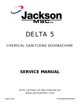
CLEARANCE
86
3
4
[2203 mm]
WITH DOOR
OPEN
A
73
[1854 mm]
17 [432 mm]
C
B
28
5
8
[727 mm]
25 [635 mm]
1
4
15 [387 mm]
LEGEND
A - Drain 1 1/2" NPT
B - Water Inlet 3/4" NPT
C - Electrical Connection
increased 2" using the machine's
adjustable feet.
73
[1856 mm]
4
[102 mm]
MINIMUM
4 [124 mm]
7
8
5
8
A
4
[102 mm]
MINIMUM
20
[508 mm]
D
D
5 1/2
(140 mm)
D - Optional Steam Connection 3/4” NPT
DIMENSIONS
SPECIFICATIONS

3
07610-002-23-32-AD
( 3 mm)
2
3
4
(79mm)
15
1
4
(387mm)
11
3
4
(298mm)
17 (432mm)
2 ( 7mm)
73 (1856mm)
34 (861mm)
93 (2362mm)
B
88 (2235mm)
C
1
0
mm
5
1
4
(134mm)
LEGEND
A - Drain 1 1/2" NPT
B - Water Inlet 3/4" NPT
C - Electrical Connection
increased 2" using the machine's
adjustable feet.
4
(
(
2
8
5
8
7
2
7 ( mm)
CLEARANCE
2
6
68
8
7
3
2
5
8
A
B
MINIMUM
DIMENSIONS - HH-E-VER
SPECIFICATIONS

07610-002-23-32-AD
4
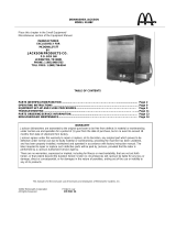
TABLE DIMENSIONS
SPECIFICATIONS
30
(762 mm)
8 1/4
(210 mm)
20 1/2”
(521 mm)
OPENING
4 (102 mm) MIN
ALIGN WITH TABLE -
DISTANCE CAN VARY
4 (102 mm) MIN
ALIGN WITH TABLE -
DISTANCE CAN VARY
8 1/4
(210 mm)
Distance from wall
to rear rack rail.
Distance from wall
to right rack rail.
Control Panel
1 1/4”
[32 mm]
1 3/8”
[35 mm]
20 1/2”
[521 mm]
OPENING
30
(762 mm)
8 1/4
(210 mm)
20 1/2”
(521 mm)
OPENING
4 (102 mm) MIN
ALIGN WITH TABLE -
DISTANCE CAN VARY
Distance from wall
to rear rack rail.
Control Panel
20 1/2”
(521 mm)
OPENING
For corner
install instructions:
CORNER INSTALLATION
STRAIGHT-THROUGH INSTALLATION

5
07610-002-23-32-AD
OPERATING CYCLES (SECONDS):
Wash Rinse Dwell Total
HH-E-VER:
Wash Time 45
Rinse Time 15
Dwell Time 2
Condensate Removal 30
Total 92
OPERATING CAPACITY:
Normal Cycle
Racks per Hour 53
Dishes per Hour 1325
Glasses per Hour 1908
Medium Cycle
Racks per Hour 28
Dishes per Hour 700
Glasses per Hour 1008
Heavy Cycle
Racks per Hour 19
Dishes per Hour 475
Glasses per Hour 684
Extra-heavy Cycle
Racks per Hour 11
Dishes per Hour 275
Glasses per Hour 396
Tank Capacity:
Rinse Tank (gallons/liters) 3.0/11.4
Wash Tank (gallons/liters) 8.0/30.3
MOTOR HP:
Wash Motor HP 2.0
WATER REQUIREMENTS:
TempStar HH-E:
Wash Temperature (minimum) (°F/°C) 155/68
Rinse Temperature (minimum) (°F/°C) 180/83
Inlet Water Temperature (°F/°C)
12 kW Rinse Heater (°F/°C) 140/60
14 kW Rinse Heater (°F/°C) 110/44
Flow Pressure (PSI) 10 ± 2
Water Line Size (NPT) 1/2"
Drain Line Size (NPT) 1 1/2"
TempStar HH-E-VER:
Wash Temperature (minimum) (°F/°C) 155/68
Rinse Temperature (minimum) (°F/°C) 180/83
Inlet Water Temperature (°F/°C) 40-90/4.4-32.2
Flow Pressure (PSI) 10 ± 2
Water Line Size (NPT) 3/4"
Drain Line Size (NPT) 1 1/2"
TempStar HH-E NB/Tempstar HH S:
Wash Temperature (minimum) (°F/°C) 150/66
Rinse Temperature (minimum) (°F/°C) 180/83
Inlet Water Temperature (°F/°C) 180/83
Flow Pressure (PSI) 20 ± 5
Water Line Size (NPT) 3/4"
Drain Line Size (NPT) 1 1/2"
HH S STEAM REQUIREMENTS:
Coil Size 3/4"
Steam Flow Pressure (PSI) 10-30
Consumption @ 15 PSI (lbs/hr) 45
ENERGY SPECIFICATIONS
HH-E-VER
Latent Heat 4678 Btu/Hr
Sensible Heat 5190 Btu/Hr
OPERATING PARAMETERS
SPECIFICATIONS
NOTICE
i
Always refer to the machine data plate for specic electrical and water requirements.
The material provided on this page is for reference only and is subject to change without notice.
HH-E 40 10 10 60
Normal 45 15 2 62
Medium 103 15 2 120
Heavy 163 15 2 180
Extra-Heavy 283 15 2 300

07610-002-23-32-AD
6
TEMPSTAR HH-E 70° Rise (14 kW) & TEMPSTAR HH-E-VER
Volts Phase Freq
Wash
Motor
Wash
Heater
Rinse
Heater
Total Load MCA MOP
208 1 60 Hz 11.2 A 19.7 A 50.6 A 81.5 A 84.3 A 95.0 A
230 1 60 Hz 11.2 A 21.8 A 55.9 A 88.9 A 91.7 A 100.0 A
208 3 60 Hz 11.2 A 11.4 A 29.2 A 51.8 A 54.6 A 65.0 A
230 3 60 Hz 11.2 A 12.6 A 32.3 A 56.1 A 58.9 A 70.0 A
460 3 60 Hz 3.0 A 6.3 A 16.1 A 25.4 A 26.2 A 30.0 A
TEMPSTAR HH-E 40° Rise (12 kW)
Volts Phase Freq
Wash
Motor
Wash
Heater
Rinse
Heater
Total Load MCA MOP
208 1 60 Hz 11.2 A 19.7 A 43.3 A 74.2 A 77.0 A 85.0 A
230 1 60 Hz 11.2 A 21.8 A 47.9 A 80.9 A 83.7 A 90.0 A
208 3 60 Hz 11.2 A 11.4 A 25.0 A 47.6 A 50.4 A 60.0 A
230 3 60 Hz 11.2 A 12.6 A 27.7 A 51.5 A 54.3 A 65.0 A
460 3 60 Hz 3.0 A 6.3 A 13.8 A 23.1 A 23.9 A 25.0 A
ELECTRICAL REQUIREMENTS
SPECIFICATIONS
On three-phase machines, imbalanced wild leg goes to L3.
Also see the Motor Rotation section.
NOTICE
Local codes may require more stringent protection than what is displayed here. Always verify with your electrical service
contractor that your circuit protection is adequate and meets all applicable national and local codes. Numbers in this manual
are for reference and may change without notice.
i
i

7
07610-002-23-32-AD
ELECTRICAL REQUIREMENTS
SPECIFICATIONS
On three-phase machines, imbalanced wild leg goes to L3.
Also see the Motor Rotation section.
NOTICE
Local codes may require more stringent protection than what is displayed here. Always verify with your electrical service
contractor that your circuit protection is adequate and meets all applicable national and local codes. Numbers in this manual
are for reference and may change without notice.
TEMPSTAR HH-E NB
Volts Phase Freq
Wash
Motor
Wash
Heater
Rinse
Heater
Total Load MCA MOP
208 1 60 Hz 11.2 A 19.7 A N/A 30.9 A 33.7 A 40.0 A
230 1 60 Hz 11.2 A 21.8 A N/A 33.0 A 35.8 A 45.0 A
208 3 60 Hz 11.2 A 11.4 A N/A 22.6 A 25.4 A 35.0 A
230 3 60 Hz 11.2 A 12.6 A N/A 23.8 A 26.6 A 35.0 A
460 3 60 Hz 3.0 A 6.3 A N/A 9.3 A 10.1 A 15.0 A
TEMPSTAR HH S
Volts Phase Freq
Wash
Motor
Wash
Heater
Rinse
Heater
Total Load MCA MOP
208 1 60 Hz 11.2 A N/A N/A 11.2 A 14.0 A 25.0 A
230 1 60 Hz 11.2 A N/A N/A 11.2 A 14.0 A 25.0 A
208 3 60 Hz 11.2 A N/A N/A 11.2 A 14.0 A 25.0 A
230 3 60 Hz 11.2 A N/A N/A 11.2 A 14.0 A 25.0 A
460 3 60 Hz 3.0 A N/A N/A 3.0 A 3.8 A 15.0 A
i
i

07610-002-23-32-AD
8
INSTRUCTIONS
INSTALLATION
Before installing the unit, check the packaging and machine for damage. If the packaging
is damaged, the machine might also be damaged. If there is damage to both packaging
and machine, do not throw away the packaging. The machine has been inspected and
packed at the factory and is expected to arrive to you in new, undamaged condition.
However, rough handling by carriers or others might result in damage to the unit while
in transit. If so, do not return the unit to the manufacturer. Instead, contact the carrier
and ask them to send a representative to the site to inspect the damage and complete
an inspection report. You must contact the carrier and the dealer that sold you the unit
within 48 hours of receiving the machine.
While unpacking the machine, ensure that there are no missing parts. If an item is
missing, contact the manufacturer immediately.
While unpacking an HH-E-VER unit, note that the VER system is packaged separately.
Click here or on the instructions icon for a guide on mounting the VER system to the
machine.
The machine must be level in its operating location to prevent damage to the machine
during operation and to ensure the best results. The unit comes with four adjustable
bullet feet, which can be turned using a pair of channel locks (or by hand if the unit can
be raised safely). Ensure that the unit is level from side-to-side and front-to-back before
making any connections.
Plumbing connections must comply with all applicable local, state, and national
plumbing codes. The plumber is responsible for ensuring that the incoming water line
is thoroughly ushed before connecting it to any component of the machine. It is very
important to remove all foreign debris from the water line that might potentially get
trapped in the valves or cause an obstruction. Any valves that are fouled as a result of
foreign matter left in the water line—and any expenses resulting from this fouling—are
not the responsibility of the manufacturer.
A water hardness test must be performed to determine if a water treatment system
needs to be installed.
If water hardness tests at greater than 3 GPG, install the Scaltrol Water Treatment
system (see the Plumbing Options page) into the water line before the machine’s
incoming water connection point. A water shut-off valve should be installed to allow
access for service.
INSPECTION
LEVELING
UNPACKING
PLUMBING
A water hardness test
MUST be performed.
Do not throw away
packaging if damage is
evident!
WATER SUPPLY
CONNECTION:
WATER HARDNESS
GREATER THAN
3 GPG
The plumber MUST ush
the incoming water line!
HH-E-VER
ASSEMBLY

9
07610-002-23-32-AD
WATER SUPPLY
CONNECTION:
WATER HARDNESS
OF 3 GPG OR LESS
PRESSURE
REGULATOR
SHOCK ABSORBER
CONNECTING THE
DRAIN LINE
If water hardness tests at less than 3 GPG, install the water supply line directly to
the machine’s incoming water connection point. A water shut-off valve should be
installed to allow access for service.
The steam machines come with lines to connect the source steam. Connect all steam
lines to the machine as all applicable codes provide. See machine data plate for
information concerning steam ow pressure. Click here or on the instructions icon for
the Steam Booster manual.
The manufacturer recommends the installation of a water pressure regulator in the
incoming water line to ensure proper owrate at all times and offers these devices as
options (see the Plumbing Options page). The PRV comes standard on the TempStar
HH-E-VER but ships inside the machine. Click here for install instructions.
Do not confuse static pressure with ow pressure. Static pressure is the line pressure
in a “no ow” condition (all valves and services are closed). Flow pressure is the
pressure in the ll line when the ll valve is opened during the cycle.
The manufacturer also recommends the installation of a shock absorber in the
incoming water line and offers these devices as options. This prevents line hammer/
hydraulic shock—induced by the solenoid valve as it operates—from causing damage
to the equipment (see the Plumbing Options page).
The machine's drain is a gravity-discharge drain. All piping from the 1 1/2” NPT
connection on the wash tank must be pitched (1/4” per foot) to the oor or sink drain.
All piping from the machine to the drain must be a minimum 1 1/2” NPT and must not
be reduced. There must also be an air-gap between the machine drain line and the
oor sink or drain. If a grease trap is required by code, it should have a ow capacity
of 5 GPM.
Determine which exhaust fan timer is on the machine (located in the control box)
and click the instructions icon beside that timer to access programming instructions.
STEAM LINE
CONNECTION
INSTRUCTIONS
INSTALLATION
EXHAUST FAN
TIMER

07610-002-23-32-AD
10
INSTRUCTIONS
INSTALLATION
CHEMICAL
CONNECTIONS
PLUMBING CHECK
Slowly turn on the water supply to the machine after the incoming ll line and drain
line have been installed. Check for any leaks and repair as required. All leaks must be
repaired before operating the machine.
Detergent
Connect detergent by removing the bulkhead tting on the back of the machine and
replacing it with the appropriate dispensing equipment.
Chemical connections
should be made by the
chemical supplier.
Rinse-aid
Connect rinse-aid by removing one of the brass plugs at the base of the rinse injector
and replacing it with the appropriate dispensing equipment.
See "Plumbing - HH-E-VER" page for a depiction of the VER rinse injector.
Rinse-aid
Using deionized water or
other aggressive uids
will result in corrosion and
failure of components and
will void the warranty.
WARNING! Some of the
chemicals used in
dishwashing may cause
chemical burns if they
come in contact with skin.
Wear protective gear when
handling these chemicals.
If any skin comes in
contact with these
chemicals, immediately
follow the instructions
provided with the
chemicals for treatment.
!
WARNING
Dispenser Electrical Connections
The electrical connections for chemical dispensers are made on a fuse block inside
the control box. Click here for a depiction of the fuse block and connection locations.
Detergent Probe
Installs Here

11
07610-002-23-32-AD
Electrical and grounding conductors must comply with the applicable portions of the
National Electric Code ANSI/NFPA 70 (latest edition) and/or other electrical codes.
The data plate is located on the right side of the machine. Refer to the data plate for
machine operating requirements, machine voltage, total amperage, and serial number.
1. Open the control box by using a phillips screwdriver to remove the four screws on
the front cover of the control box.
2. Install 3/4” conduit into the pre-punched holes in the back of the control box.
3. Route power wires and connect to power block and grounding lug.
4. Install the service wires (L3 for 3-Phase only) to the appropriate terminals as they
are marked on the terminal block.
5. Install the grounding wire into the lug provided.
6. Tighten the connections.
“DE-OX” or similar anti-oxidation agent should be used on all power
connections.
CAUTION! Improperly connecting external devices can cause damage to the
machine and/or electrical infrastructure! Click here for a wiring guide.
On 3-Phase machines only, correct pump motor rotation must be veried before
the machine is operated. Failure to do so can result in damage to the machine and
components.
1. Follow the "Filling the Wash Tub" section.
2. Locate the wash pump motor and identify the arrow decal which shows the
correct motor rotation.
3. Flip the mode switch to "MANUAL" and start the machine.
4. Observe the rotation of impeller and quickly stop the machine.
5. If rotation is incorrect, disconnect electrical power and reverse the
L1 and L2 connections at terminal block shown in the section above.
ELECTRICAL POWER
CONNECTIONS
Disconnect electrical
power supplies and
lockout/tagout in
accordance with
appropriate procedures
and codes at the
disconnect switch.
!
CAUTION
INSTRUCTIONS
INSTALLATION
Imbalanced
wild leg goes
to L3.
NOTICE
L1
L2
L3
Ground
3Φ
NOTICE
MOTOR ROTATION
i
CAUTION! On 3-Phase
machines only, correct
pump motor rotation
must be veried
before operation!
!
CAUTION
Rotation
Impeller
/