Page is loading ...

KIT CONTENTS:
1– 25” Drag Link
1– 42” Tie Rod Link
1– Upper LH Thread Tie Rod End
1– Lower RH Thread Tie Rod End
1– Passengers Side LH Thread Tie
Rod End
1– Drivers Side RH Thread Tie Rod
Thank you for choosing Rough Country for all your vehicle needs.
Please read instructions before beginning installation. Check the kit hardware against the kit contents shown below. Be
sure you have all needed parts and know where they go.
If question exist, please call us @1-800-222-7023. We will be happy to answer any questions concerning this product.
Check all fasteners for proper torque. Check to ensure for adequate clearance between all components.
Check and retighten wheels at 50 miles and again at 500 miles. Periodically check all hardware for tightness.
TOOLS NEEDED:
15mm wrench and socket
18mm wrench and socket
19mm wrench and socket
1 1/6 wrench
1 1/4 wrench
Side Cutting Pliers
Drill motor
5/8 Drill
7° Reamer
Ratchet
Tape measure
HARDWARE INCLUDED:
2– Left Hand Jam Nuts
2– Right Hand Jam Nuts
4– Castle Nuts
4– Cotter Pins
Torque Specs:
Size Grade 5 Grade 8 Size Class 8.8 Class 10.9
5/16” 15 ft/lbs 20ft/lbs 6MM 5ft/lbs 9ft/lbs
3/8” 30 ft/lbs 35ft/lbs 8MM 18ft/lbs 23ft/lbs
7/16” 45 ft/lbs 60ft/lbs 10MM 32ft/lbs 45ft/lbs
1/2” 65 ft/lbs 90ft/lbs 12MM 55ft/lbs 75ft/lbs
9/16” 95 ft/lbs 130ft/lbs 14MM 85ft/lbs 120ft/lbs
5/8” 135ft/lbs 175ft/lbs 16MM 130ft/lbs 165ft/lbs
3/4” 185ft/lbs 280ft/lbs 18MM 170ft/lbs 240ft/lbs
JEEP TJ/XJ/MJ/ZJ HD Steering
921106040
*10604BAG*
10604BAG

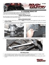
1. Park the vehicle on a level surface and chock the rear wheels.
2. Jack up the front of the vehicle. Place jack stands under the frame rails and lower onto jack stands letting the front
suspension hang.
3. Remove the tires and wheels using a 19mm socket.
4. Remove the stabilizer from the axle. Using a 15mm socket and 18mm wrench. See Photo 1.
5. Remove the cotter pin from all of the tie rod ends use side cutting plyers. See Photo 2.
6. Loosen the nut on the tie rod end. Use a 19mm wrench. See Photo 3.
7. Unseat the taper on the tie rod end, using a hammer. Remove the nut from the tie rod end and remove from the
knuckle.. See Photo 4.
8. Repeat steps 5-7 on the opposite side tie rod end, and remove the tie rod from the knuckle. See Photo 5.
9. Repeat steps 5-7 to remove the drag link from the pitman arm. See Photo 6.
Photo 1 Photo 2
Photo 3 Photo 4
Photo 5 Photo 6
Remove the bolt from the stabilizer. Remove the cotter pin.
Loosen the nut on the tie rod end. Unseat the taper on the tie rod end.
Remove the nut and the tie rod end. Remove the pitman arm nut.
INSTALLATION INSTRUCTONS

10. Once the steering stabilizer, drivers and passengers side drag link from the knuckle, and tie rod from the pitman arm
have been taken loose, remove the steering link from the vehicle. See Photo 7. Set this aside, as it will not be re-
used.
11. Brace the drivers side knuckle so it will not move, use a drill motor and a 5/8 drill to open up the hole in the knuckle.
See Photo 8.
12. Brace the passengers side knuckle so that it will not move, use a drill motor and a 5/8 drill to open up the hole in the
knuckle. See Photo 9.
13. It may be easier to remove the pitman arm from the vehicle to drill, use a drill motor and a 5/8 drill to open up the
hole in the pitman arm. See Photo 10.
14. Using the 7° reamer, use a pair of calipers to find 3/4” of an inch, outside diameter for the reaming depth. Mark this
depth onto the reamer using masking tape or a permanent marker. See Photo 11.
15. Use a lubricant on the reamer when reaming out the bottom of the drilled hole. NOTE: DO NOT ream all the way
to the mark made onto the reamer, without confirming the ball joint depth for proper fitment of the tie rod
end, castle nut and cotter pin. See Photo 12.
Photo 7 Photo 8
Photo 9 Photo 10
Photo 11 Photo 12
Remove OE steering link from the vehicle. Drill hole size to 5/8.
Drill hole size to 5/8. Drill hole size to 5/8.
Mark 3/4 inch on the 7 degree reamer. Use care when reaming the knuckle.

16. Confirming the depth of the ball joint as shown in photo 13. Slowly ream until the castle nut will seat the ball joint
allowing the cotter pin to go into the ball joint. See Photo 13 and 14.
17. Using care not to over ream the hole will allow the proper ball joint working room in between the knuckle and the ball
joint. See Notes in Photo 14.
18. Repeat steps 14-17 on the following passengers side knuckle and the pitman arm. Install the pitman arm if it has
been removed to perform the steps above. See Photo 15 and 16.
19. Assemble the 4 jam nuts onto the tie rods. See Photo 17.
20. Install the offset tie rods into the 42” tie rod link, screw the tie rods all the way in. NOTE: The passengers side
link is left hand thread, it is recognizable by the wrench flat side. See Photo 18.
Photo 13 Photo 14
Photo 15 Photo 16
Photo 17 Photo 18
Check depth, Do not over ream taper. NOTE : Ball joint working room.
Use care when reaming pass. side knuckle. Use care when reaming the pitman arm.
Supplied tie rod ends. Assemble tie rods onto the tie rod link.
NOTE: Castle nut will not
seat the ball joint allowing
the cotter pin to go into the
ball joint and nut.
NOTE: Castle nut has
enough seating clearance
to allow the cotter pin to be
installed.
NOTE: The left hand thread
is the wrench flat side.

21. Install the 2 joints that are not off set into the 25” drag link, screw the tie rods all the way in. NOTE: The left hand
thread drag link end will be attached to the pitman arm. It is recognizable by the wrench flat side.
See Photo 19.
22. Install the assembled tie rod link onto the vehicle, adjust the tie rod to a starting length of 52 inches, measure from
center of both tie rod grease fittings. See Photo 20.
23. Tighten the tie rod castle nuts using 1 1/16 wrench and install the cotter pin on each side. See Photo 21.
24. Tighten the jam nuts on each side of the tie rod link, using a 1 1/4 wrench. See Photo 22.
25. Install the left hand thread tie rod end onto the pitman arm, tighten using a 1 1/16 wrench and install the cotter pin.
See Photo 23.
26. Install the tie rod into the mounting hole on the passengers side tie rod end, tighten using a 1 1/16 wrench and install
the cotter pin. See Photo 24.
Photo 19 Photo 20
Photo 21 Photo 22
Photo 23 Photo 24
Install rod ends onto the drag link. Set a starting length of 52 inches.
Tighten the castle nut. Tighten the jam nut.
Tighten the castle nut. Tighten the castle nut installed in the rod end.
NOTE: The left hand thread
is the wrench flat side.

27. Adjust the drag link to a starting length of 34 inches, measure from center of both tie rod grease fittings. See Photo
25.
28. Once the starting length has been set tighten the jam nuts to the tie rod link. See Photo 26.
29. Check over all of the installed steering components, tightening of all the jam nuts on the rod end links, tightening of
all the castle nuts and cotter pins installed and secured. See Photo 27.
30. Make sure the tie rod connected to the pitman arm has plenty of working room for compression and droop as the
suspension travels up and down and turns right to left.
31. Install the wheels and tires, tighten using a 19mm socket.
32. Lift the vehicle up and remove the jack stands, lower the vehicle onto the ground.
33. The vehicle will need an alignment once the installation is complete.
By purchasing any item sold by Rough Country, LLC, the buyer expressly warrants that he/she is in compliance with all
applicable , State, and Local laws and regulations regarding the purchase, ownership, and use of the item. It shall be
the buyers responsibility to comply with all Federal, State and Local laws governing the sales of any
items listed, illustrated or sold. The buyer expressly agrees to indemnify and hold harmless Rough
Country, LLC for all claims resulting directly or indirectly from the purchase, ownership, or use of the
items.
Photo 25 Photo 26
Set a starting length of 34 inches. Tighten the jam nuts on the tie rod ends.
Photo 27
Check over all installed components.
/