Page is loading ...

386—STEERING
CHRYSLER SERVICE MANUAL
MANUAL STEERING
DATA
AND
SPECIFICATIONS
MODELS
King Pin Diameter
King Pin Bushings (Manual Steering) Type
Upper
Lower
King Pin Bushings (Power Steering) Type
Upper
Lower
Dimensions of Lower Bushings
Inside Diameter
Outside Diameter
Length
Ream After Installation
C-67, C-68, C-69, C-70
.7953 in.
Needle Type Bearing
Bushing
Floating Bushing
Floating Bushing
.787 to .789 in.
.823
to .825 in.
1.195 to 1.205 in.
.7960 to .7975 in.
COAXIAL POWER STEERING
MODELS
Fluid Capacity of Hydraulic System
Fluid Capacity of Worm Housing
Type of Fluid
Maximum Pump Pressure
Maximum Fluid Flow at
3,000
R.P.M
Maximum Pump Rotor Clearances:
Between Rotor Lobes
Between Outer Rotor and Bushing
C-67, C-68, C-69, C-70
2qts.
lpt.
Automatic Transmission Fluid,
Type A
750 to 800 psi.
2 gal. (Minimum)
.008 in.
.006 in.

CHRYSLER SERVICE MANUAL
STEERING—387
COAXIAL POWER STEERING (Cont'd)
End Clearance (Between Rotors and
Face of Body)
Flow Control Valve Spring
Free Length
Working Length
Force at Working Length
Pressure Relief Valve Spring
Free Length
Working Length
Force at Working Length,
Front End Alignment
Steering Gear Ratio
Piston Rod Snap Ring Gap
(Upper and Lower) ...
.001
to .002 in.
2.13 in.
1.20 in.
14 lbs. ± lVo lbs.
1.51 in.
1.18 in.
30 to 33 lbs.
16.2:1
2
%4 in.
SPECIAL TOOLS
MANUAL STEERING GEAR
Tool Number
C-143
C-328
C-611
C-3428
C-619
C-630
Tool Name
Puller-—Steering Arm
Bushing—King Pin Remover
Bushing—Eccentric Adjusting
Puller—Steering Wheel
Bushing—Eccentric Adjusting
Reamer—Pilot Bushing

388—STEERING
CHRYSLER SERVICE MANUAL
COAXIAL POWER STEERING GEAR
Tool Number Tool Name
C-760 Pliers—Gear Snap Ring—Straight Type
C-3102 Gauge—Hydraulic Pump and Gear Checking
C-3106 Pliers—Gear Snap Ring—Right Angle
C-3107 Wrench—Adjustable Spanner
C-3108 Studs—(Pr.) Power Cylinder
C-
3109 Spacer—Aligning Unit In Chassis
C-3112 Puller—Steering Gear Tube Coupling Adapters for C-293 Puller (C-3145
Covers C-3112 Parts and C-293 Parts Required To Pull Coupling)
C-3113 Driver—Steering Gear Shaft Outer Bearing
C-3114 Driver—Steering Gear Shaft Inner Bearing
C-3116 Pilots—(Pr.)Reservoir Installing
C-3117 Plug—Oil Pump Return Hole (Tapered) (Small)
C-3128 Pliers—Pump Shaft Rear Bearing Ring
C-3129 Driver—Pump Oil Seal and Bearing
C-3130 Thimble—Protector—Pump Oil Seal
C-3136 Sleeve—Shaft Oil Seal Installing
C-3137 Remover—Shaft Oil Seal
C-3141 Driver—Valve Block Adjusting Pin Roller
C-3142 Driver—Steering Gear Shaft Inner Seal
C-3143 Driver—Steering Tube Oil Seal In Valve Body Cap
C-3189 Plug—Oil Pump Return Hole (Tapered) (Large)
C-485,
C-524 or
C-3005..
Wrench—Foot-Pound Torque
C-612 Puller—Steering Wheel
C-685 or C-3380 Wrench—Inch-Pound Torque
SP-2623 Puller Screw—For Use With C-143 Puller (Previously Released)
C-3185 Remover—Pump Shaft Bushings and Seal
C-3211 Hose—High Pressure P/S Test
C-3214 Puller—Main Bearing

CHRYSLER SERVICE MANUAL
STEERING—389
COAXIAL POWER STEERING GEAR (Cont'd)
Tool Number Tool Name
C-3227 Wrench—Flange Holding
C-3228 Thimble—Shaft Oil Seal Protecting
C-3229 Pliers
C-3230 Driver—Shaft Oil Seal Installing
C-3233 Driver—Shaft Bushing Installing
C-3234 Adapter—For using C-3214 Puller
C-3250 Pliers—Hose Clamp
C-3251 Driver—Main Bearing Installing
C-3309 Gauge—Oil Pump, pressure checking
C-3317 Driver—Worm Housing Oil Seal
C-3318 Hose—Low Pressure P/S Test W/adapters
C-3319 Nut—Worm Shaft Holding
C-3320 Wrench—Worm Shaft Bearing Adjusting Nut
C-3321 Wrench—Worm Connector Holding
C-3322 Remover and Installer Worm Housing Bearing Cups
C-3323 Fixture—Gear Assembly Holding
C-3328 Spanner—Upper Piston Rod Nut
C-3329 Thimble—Valve Control Spacer Seal Installing
C-3331 Driver—Housing Head and Gear Housing Seal
C-3333 Driver—Remove and Install Gear Shaft Bearing
C-3344—SP-2604 Installer—Piston and Ring Assembly
C-3350 Remover and Installer—Gear Shaft Oil Seal
C-3437 Protector—Lower Piston Rod Seal
C-3392 Wedge—Coupling Removing—(Not Required If C-3112 Is Available)
C-3398 Remover and Installer—Gear Shift Rod Bushings
C-3399 Tool—Shifter Dial Bulb Removing and Installing
C-3401 Thimble—Gearshift Adjusting Screw "0" Ring Installing
C-3469 Flange—Upper Housing—Used For Pretesting for Hydraulic Leaks

390—STEERING CHRYSLER SERVICE MANUAL
TIGHTENING REFERENCE
MANUAL STEERING
Foot-Pounds
Steering Gear to Frame Bolt 50
Steering Gear Arm (Pitman) Lock Bolt Nut. 80
Steering Knuckle Tie Rod Clamp Bolt 15
Steering Gear Mounting Bracket Bolts 50
Steering Wheel Nut 40
Steering Knuckle Tie Rod End Ball Nut 75
Intermediate Steering Arm Pin Nut 50
POWER STEERING GEAR ASSEMBLY
Foot-Pounds
Pump Body to Cover Bolts 30-35
Pump Reservoir to Pump Body Bolts 12-17
Pump Mounting Bolts 18-23
Pump Reservoir Mounting Stud 30-35
Steering Knuckle Arm Nuts (Brake Anchor Nuts) 55-75
Steering Gear Arm to Shaft Nut 100-125
Steering Arm to Transverse Link Nut 50-55
Steering Gear Assembly Mounting to Frame 65-70
Steering Wheel to Steering Shaft Nut 35-40
Jacket to Instrument Panel Screws 15-20
Tie Rod Clamp Bolts 10-15

CHRYSLER SERVICE MANUAL-
STEERING—391
POWER STEERING GEAR ASSEMBLY (Cont'd)
Foot-Pounds
Tie Rod to Steering Knuckle Arm Nuts 45-75
Pump Coupling Attaching Screw 15-20
Pump Flow Control and Relief
Valve
Adapter (Retaining) 45-50
Pump Coupling Flange Attaching Screw 10-12
Upper Piston Rod Nut 25-30
Ball Guide Clamp Screws 10-12
Worm Housing to Gear Housing Screws 25-30
Gear Shaft Adjusting Screw Lock Nut 35-40
RESERVOIR
Thread Size Foot-Pounds
Reservoir Cover Bolt %
6
x 24 8
Relief Valve Assembly Cap 1x8 8
Hose Connector Inlet % x 18 30
PUMP
Thread Size Foot-Pounds
Pump Assembly Bolt %
6
x 18 20
Hose Connector Outlet % x 18 30
By-Pass Plug % x 16 50
Relief Valve Plug 1 x 14 50
Flow Divider Valve Plug 1% x 12 50
94 e Drain Tube Nut % x 24 *y
2
to % Turn
or 6 to 10
* The number of turns specified is after initial finger tightening.

392—STEERING
CHRYSLER SERVICE MANUAL
KNOB
COVER
SCREW
GROMMET
JACKET
INSULATOR
SWITCH
BRACKET
LEVER
GROMMET
WASHER
WASHER
OIL
SEAL
WASHER
LOCKWASHER
NUT
NUT
OILSEM
'^J^\\
BUSHINGS<^T%
\ *
CUP
CAGE
AND
ROLLERS
TUBE
AND
WORM
CAGE
AND
ROLLERS
OIL
SEAL
SHIMS
NUT
54x677
A
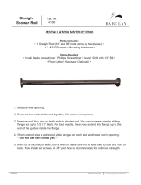
Fig.
1—Typical Steering Gear (Exploded View)

CHRYSLER SERVICE MANUAL
STEERING—393
Section
X
STEERING
(SEE FIG.
1)
1.
LINKAGE
The symmetrical idler arm type
of
steering,
as
shown
in
Figure 2,
is
used on
all
models.
A
cen-
ter link relays the motion from the Pitman arm
to an idler arm at its opposite end. The idler arm
is mounted
on a
bracket attached
to the
frame.
Two equal length tie rods connect from the cen-
ter relay link to the steering knuckle arms. Both
tie rods
are
threaded
for
proper
toe
aligning
adjustment.
2.
STEERING GEAR (THREE-TOOTH ROLLER
AND WORM) (Mechanical)
A three-tooth roller
is
mounted
on
needle roller
bearings on
a
steel cross-shaft inserted through
the steering gear shaft.
The worm
is
integral with
the
steering tube
and
is
supported
at
each
end by
tapered roller
bearings. The worm bearing pre-load is adjusted
by means
of
shims placed between
the
housing
and housing end cover. The steering gear shaft
rotates
in
two bronze bushings pressed into
the
steering gear housing.
The
three-tooth roller
on
the
shaft
is
meshed with
the
worm. When
the steering wheel
is
turned,
the
worm rotates
the steering gear shaft
and
roller, moving
the
Pitman arm, which
is
splined
to the
end
of the
shaft and held
in
place with
a nut.
Backlash between the steering gear shaft rol-
ler tooth and
the
worm
is
controlled
by an ad-
justing screw that is threaded through the shaft
and roller cover. The base end
of
the adjusting
screw
is
engaged
in a
slot
in the end of the
steering gear shaft. Correct backlash
can be
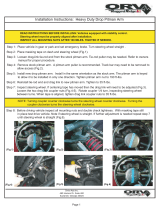
TIE
ROD
ENDS-INNER
CENTER LINK
IDLER
ARM
STEERING GEAR
STEERING KNUCKLE
ARM-RIGHT
TIE
ROD
END-OUTER
STEERING KNUCKLE
ARM-LEFT
STEERING GEAR
ARM
55x5
Fig.
2—Idler Arm Type Steering Linkage

394—STEERING
CHRYSLER SERVICE MANUAL
obtained by turning the adjusting screw in or
out, as required.
The steering wheel and Pitman arm are
splined to the steering tube and steering gear
shaft, respectively. Both the steering wheel and
the Pitman arm have master serrations to in-
sure correct installation.
The high point is the point of least clearance
between the worm and roller and is at the mid-
point of the worm and roller travel.
An oil seal is installed in the bore of the
steering gear housing at the outer end of the
shaft to prevent oil leakage and to keep foreign
material from entering the steering unit.
3.
REMOVAL OF STEERING WHEEL
ASSEMBLY
Disconnect battery and center the steering
wheel in the straight-ahead position. Press down
on the horn blowing ring ornament and turn
counter-clockwise. Lift out ornament retaining
spring and pad. Disconnect horn wire from ter-
minal on travel plate and insulator assembly.
Remove bushing, travel plate, horn blowing con-
tact ring spring, and triangular ground plate.
Curl and push horn wire into the steering gear
tube to make room for steering wheel puller
pilot. Remove the steering wheel nut. Attach
puller and remove steering wheel.
4.
REMOVAL OF STEERING GEAR
ASSEMBLY
It is not necessary to remove the complete steer-
ing column and mast assembly from the car for
servicing the gear chuck and worm shaft. To
remove the gear chuck and worm shaft assem-
bly proceed as follows. Disconnect the battery,
press down on the horn ring ornament while ro-
tating it, and remove ornament. Remove steer-
ing column worm shaft nut. Pull steering wheel
with puller. Loosen jacket bracket bolts at in-
strument panel. Remove dust pad retaining
screws. Raise front of car and remove steering
gear (Pitman) arm from gear shaft. Loosen
jacket to gear chuck clamp bolt. Remove gear
chuck to frame attaching bolts and work gear
chuck and shaft assembly out of jacket. Remove
assembly from lower side of car.
5.
DISASSEMBLY OF STEERING GEAR
(Unit Removed From Car)
To disassemble the Manual Steering Gear As-
sembly, proceed as follows:
Drain lubricant from the steering gear hous-
ing. Mount the gear assembly in a suitable bench
vise,
holding the assembly by the housing to
chassis mounting flange, with the steering col-
umn in the horizontal position. Remove the shaft
cover attaching cap screws, cover, gasket and
steering gear shaft, and roller tooth assembly.
Loosen the column jacket clamp bolt, pry
open clamp and remove column jacket from
steering housing. Remove steering worm, lower
oil seal housing cover bolts, cover and shims.
Pull steering tube and worm assembly bearing
cups and bearing cages out of the lower end of
steering housing.
Clean the steering gear housing shaft, bear-
ings and other parts thoroughly with a suitable
cleaning solvent. Inspect roller tooth shaft, shaft
serrations, bearings, bearing cups, oil seals,
worm and tube for wear, nicks and flat spots.
Replace with new parts as necessary.
Remove roller tooth assembly shaft cover
adjusting screw nut and locking plate. Check
adjusting screw threads in cover and on the
adjusting screw. Replace if necessary.
6. ASSEMBLY OF STEERING GEAR
(Unit Removed From Car)
NOTE
When the steering gear assembly is disassem-
bled,
it is always advisable to install new seals
and gaskets to insure against oil leaks.
If either of the worm thrust tapered roller
bearings have become damaged, it is advisable
to replace both bearings. After thoroughly
cleaning all parts, assemble the parts without
any lubrication. Lubrication should be done
after the adjustments have been completed. If
bushings or needle bearings have been removed,
press new bushings or needle bearings into
place. Use new oil seals.
Insert the worm and tube into the housing
with bearings and cups in the proper order, as
shown in Figure 2. Install the shims and lower
housing cover, making sure that bearings are
seated in cups before tightening
screws.
Tighten
the cover screws evenly, turning the worm tube
at intervale to be sure no bind occurs. Final

CHRYSLER SERVICE MANUAL
STEERING—395
tightening of the screws should cause the end
play to just disappear with the torque required
to rotate the wheel from % to % of a pound,
when measured with the pull applied at rim of
wheel. If a bind in the rotation of the tube occurs
when the cover screws are fully tightened, it
will be necessary to add shim thickness until
bind just disappears. If end play is present after
final tightening, less shim thickness is required.
Shims are available in .003, .006, .011 and .025
inch. By using a micrometer to measure shims, #
the proper combination can be chosen.
Refer to Figure 2 and 3. Install the roller
shaft bearing in the housing. Before installing
the cover, turn.the adjusting screw all the way
out (counter-clockwise). When the roller shaft
assembly is completely installed, with the ex-
ception of the Pitman arm, adjust as follows:
Place the steering wheel on the tube and ro-
tate the wheel in either direction to the end of
its travel. Then, rotate in the opposite direction
to the end of travel while counting the turns.
Rotate the wheel back 1/2 the full number of
turns.
This is the center of travel (mid-travel or
high point). Turn the adjusting screw in (clock-
wise) until all end play in the roller shaft dis-
appears. Roll the wheel back and forth several
times.
There should be no bind. Rotate the wheel
to one of the ends of travel and apply a spring
scale or torque wrench. With the pull applied
at the rim of the wheel, the tension should mea-
sure from 1 to 2 pounds. Rotate the wheel back
to the center and on past the center position.
The greatest tension should be felt as the wheel
is rotated through the center position. Adjust
the bearing load by turning adjusting screw in
or out of the cover, as required. Install lock
plate, nut, and Pitman arm. Fill the gear hous-
ing with SAE 90 Fluid Gear Lubricant. Rotate
the wheel back and forth through its full travel
several times to be sure all parts are fully lu-
bricated and check for leaks.
7.
ADJUSTING WORM BEARINGS (In Car)
Rotate steering wheel to extreme right or left
and turn back % turn. Press a finger at joint
between bottom of steering wheel hub and shell.
Have another mechanic shake the front wheels
hard sideways, but not enough to turn steering
wheel. Any end play in worm bearings can be
felt at steering wheel hub. There should be no
end play at the
hub.
End play should not be con-
fused with clearance between the roller and
worm. If any excessive end play exists, remove
the steering gear arm, drain the housing, and
disconnect the horn wire at connector between
steering gear and horn.
Remove cap
screws which hold grease retainer
cover at bottom of steering gear housing. Re-
move shims of sufficient thickness between this
cover and housing to eliminate the end play in
worm, but not enough to cause binding when
cover is bolted tightly in place. Turn steering
wheel from extreme right to left. If any
stiff-
ness exists, too many shims have been removed,
or the steering gear assembly is misaligned on
car.
8. INSTALLATION AND ALIGNMENT OF
STEERING GEAR ASSEMBLY
a. Installation
Where gear chuck and worm shaft assembly has
been removed for service, install as follows.
Raise front of car, insert worm shaft into jacket
and move gear chuck assembly up into position.
It may be necessary for an assistant to guide
the top of the worm shaft through the upper
jacket alignment bearing. Install gear chuck to
bracket attaching bolts and tighten forward
bolt to a snug fit. Lower car to floor. Center the
jacket in the instrument panel and tighten
bracket bolts. Install and tighten dust pad re-
taining screws. Install steering wheel horn ring
and ornament. Raise front of car. Tighten at-
taching bolts. Install steering (Pitman) arm
and tighten nut.
b.
Alignment (All Models)
A slight bind of the steering gear is sometimes
caused by shifting of body due to loosened bolts.
If this condition occurs, body bolts should first
be tightened. Then, the steering gear should be
loosened at frame, frame bracket and dash
bracket, and allowed to seek its natural position.
Position the center of steering column in cen-
ter of instrument cluster. If this cannot be ac-
complished by the shifting of the frame bracket,
as provided for by the oversize and elongated
mounting screw holes, it will be necessary to
add metal washer shims between the frame and
frame bracket. Tighten dash bracket and tight-
en steering gear to frame.

396—STEERING
CHRYSLER SERVICE MANUAL
NOTE
Be sure the body to frame bolts are tight and
the spacers are in place. With the body bolts
tight, loosen the gear housing mounting bolts
to allow the steering gear to move in relation
to the frame. Tighten the mounting bolts to
50 foot-pounds torque. Loosen the steering col-
umn bolts that hold column to instrument panel
to determine if the column shifts its position in
relation to the support.
9. ADJUSTMENT OF ROLLER TOOTH AND
WORM (In Car)
End play of steering arm shaft and mesh of
roller tooth with steering worm may be adjusted
as follows:
Remove steering gear (Pitman) arm from
shaft and install another arm for making ad-
justments. Turn steering wheel to mid-position.
This is obtained by turning wheel to extreme
right or left, and then turning it to opposite ex-
treme, counting number of turns required. Turn
steering wheel back 1/2 the number of turns re-
quired for turning it from one extreme to the
other. With steering wheel in mid-position,
attempt to move steering gear arm back and
forth to determine whether or not there is any
backlash. There should be no backlash. But if
backlash exists, the roller tooth and worm
should be adjusted.
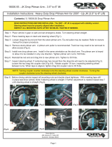
Remove roller tooth shaft adjustment screw
lock nut. Slide off lock plate far enough to clear
lock boss on roller tooth shaft cover. Tighten
roller tooth shaft adjusting screw (Fig. 3)
enough to eliminate free play between roller
tooth shaft and worm; but, it must not bind.
Slide lock plate in position against roller tooth
shaft cover and lock it. Install and tighten
roller tooth shaft adjustment screw lock nut.
Check steering gear operation again for binding
and backlash. Correct any inaccuracies in ad-
justments. Install steering gear arm with tie
rods.
10.
SERVICING IDLER ARM
Service of the idler arm is restricted to replace-
ment and adjustment. When replacing the idler
arm, disconnect the relay rod (center link) from
the idler arm. Remove the bracket attaching
screws from the bracket and frame and remove
WORM BEARING ADJUSTING SHIMS
ADJUSTING SCREW
ADJUSTING SCREW
LOCK PLATE
-LOCK PLATE
NUT
Fig.
3—Steering Gear Adjustments
54x46
the idler assembly. Screw the new idler arm
into the bracket until the shoulder on the arm
contacts the face of the bracket. Turn arm out
of bracket one complete turn. It may be neces-
sary to rotate the arm slightly to line up the
bracket for installing attaching bolts.
11.
REMOVAL AND INSTALLATION OF
STEERING KNUCKLE TIE RODS
Remove cotter pin and loosen nut on upper end
of the rod ball. With Tool C-3394, remove tie
rod from steering arm (Fig. 4). Tie rod balls
are not removable from tie rod ends. If replace-
ment of either is necessary, the complete tie rod
end and ball assembly should be replaced. Loosen
clamping bolt nut on the tie rod end. Unscrew
tie rod end assembly from tie rod.
When assembling tie rod ends to tube body,
be sure to thread the ends evenly on tube body
to the nominal length listed in Data and Speci-
fications. This is necessary to obtain proper posi-
tioning of the steering wheel with respect to the
straight-ahead position of the front wheels.
Care must be taken to make certain the clamp-
ing bolts are beneath the tie rods to prevent
interference on turns.
12.
ADJUSTMENT OF FRONT WHEEL
BEARINGS
After removing the hub cap and the grease cap,
remove the cotter pin in the bearing adjusting
nut at the outer end of the steering knuckle

CHRYSLER SERVICE MANUAL
STEERING—397
STEERING KNUCKLE
ARM
Fig.
4—Removing Tie Rod From Steering Knuckle Arm
(Tool C-3394)
(wheel spindle). Turn bearing adjusting
nut
(Fig.
5)
hand tight. Turn adjusting
nut
back
one slot. Turn
the nut
back until slot nearest
cotter
pin
hole centers over hole
and
install
a
new cotter pin.
The
bearing
nut
threads must
be
in
good condition and the cotter pin properly
installed and spread. Always use new cotter pins.
13.
RECONDITIONING FRONT WHEEL HUB
AND DRUM ASSEMBLY
Raise front
end of car
until wheel
is off
floor.
Remove hub cap. Remove wheel hub bolts. Bolts
on left wheels have left-hand threads and those
on right wheels have right-hand threads.
Re-
move wheel
hub
grease
cup
(snap type) with
special Tool C-438,
or by
prying with
a
screw
driver
and
tapping with
a
light hammer.
Re-
move threaded type
by
unscrewing
cap
from
hub.
Remove cotter
pin and
unscrew front
wheel bearing adjusting
nut.
Remove outer
bearing and pull hub
off
steering knuckle.
It is
not necessary
to
remove wheel from hub
if
hub
is
to
be removed from steering knuckle spindle.
Wheel and hub may
be
removed
as a
complete
unit. Inspect
oil
seal
and
replace
if
necessary.
Before installing front wheel
hub and
bear-
ing assembly, remove lubricant from
the hub
and bearings and make sure parts
are in
good
condition. Install inner
and
outer bearing cups
so there
is no
clearance between the hub shoul-
ders.
Pack bearings with Short Fiber Wheel
Bearing Lubricant (Medium). When installing
the
oil
seals, make certain that
the
seal flange
bottoms on the bearing cup.
14.
REMOVAL AND INSTALLATION
OF
STEERING KNUCKLE KING PINS AND
BUSHINGS
NOTE
Should servicing
of
the steering knuckle be nec-
1—Bearing
nut
2—Bearing thrust washer
3—Outer bearing cup
4—Hub
Fig.
5—Front Wheel Bearings
5—Inner bearing cone and rollers
6-Hub dust seal
7—Hub cap
8—Grease cap
°—Bearing nut cotter pin
10—Outer bearing cone and rollers
11—Steering knuckle
12—Inner bearing cup

398—STEERING CHRYSLER SERVICE MANUAL
Fig.
6—Removing Brake Support
essary, time can
be
saved by removing the steer-
ing knuckle
arm
from
the
steering knuckle.
Remove steering knuckle and brake support
as
an
assembly.
Make necessary
repairs
on
a bench.
If
it
is
done
in
this manner, eliminate removing
support. Remove brake hose connections,
but
leave brake support
on
steering knuckle.
Re-
move unit as an assembly with steering knuckle
after king pin is
removed.
Always use new bush-
ings,
seals,
and pins ivhen servicing the steering
knuckle and support assembly.
Remove wheel and hub assembly. Block brake
pedal
so it
cannot
be
depressed. Remove nuts
and bolts that fasten brake support
to
steering
knuckle. Remove steering knuckle
arm
from
steering knuckle. Remove brake hose
and
con-
nections and lift
off
brake support (Fig. 6). Do
not allow brake support and shoe assembly to be
supported
by
flexible brake hose. Remove king
pin locking pin.
Drive
a
punch into upper steering knuckle
welch plug and
pry it out of
steering knuckle.
Drive king
pin
downward, forcing
out
lower
welch plug.
A
soft brass drift should
be
used
when driving against top
of
king pin. Remove
steering knuckle upper needle bearing
or
bush-
ing
by
pulling
it
toward center knuckle, using
special
tool,
as shown in Figure
7.
Remove steer-
ing knuckle lower bushing.
If
bushing
is of
the
stationary type, use special tool to remove
it.
The upper needle bearing must
be
installed
from
top of
steering knuckle, with trade mark
Fig.
7—Removing King Pin Bushing or Bearing
1—King
pin bushing
or
bearing 2—Tool C-328
at top and oil hole
in
bearing lined
up
with
oil
hole
in
steering knuckle. Stationary type bush-
ings (Fig.
8)
should
be
line-reamed. First
re-
move
the
upper needle bearing. Install reamer
pilot bushing Tool C-631 and reamer Tool C-379.
When installing lower
and
upper floating type
bushing (Fig.
9),
place open end
of oil
groove
to the top. Both types
of
lower bushings should
49x607
Fig.
8—Bearing and Stationary Type Bushing
Installed
1—Bearing identification mark 3—Lubricant holes
2—Bushing identification line
or
notch A—3/32 inch
B-l/16inch

CHRYSLER SERVICE MANUAL
STEERING—399
Fig.
9—Bearing and Floating Type Bushing Installed
1—Bearing identification mark
2—Lubricant holes
3—Floating type bushing
A-3/16inch
be installed with oil hole in bearing lined up
with oil hole in steering knuckle. On cars
equipped with Power Steering, the king pin
bushings should be installed with the open end
of the oil groove leading towards the "O" seal
rings.
After installing the steering knuckle, make
sure it is free in the support. Binding at this
point may cause sensitive steering and car wan-
der. There should be .006 to .008 inch clearance
between the steering knuckle and the knuckle
support. This clearance can be adjusted by the
STAKE IN PLACE
AS SHOWN
STAKE SECURELY
4 PLACES AS
SHOWN BOTH
ENDS
49x701
Fig.
10—Welch Plug and King Pin Lock Pin Installed
use of shims between the steering knuckle and
the thrust bearings.
When installing a welch plug, it is necessary
to stake it after it is properly in place, as shown
in Figure 10.
Before installing hub and drum assembly,
perform Major Brake Adjustment, described
in Section III, Brakes, as applied to cars
equipped with Manual Steering. After install-
ing hub, drum and wheel assembly, check king
pin inclination, caster, camber, and toe-in or
toe-out, as outlined in Front Wheel Alignment
in this Section. Adjust brakes.
COAXIAL POWER STEERING
15.
DESCRIPTION (Fig. 11)
The Coaxial Power Steering Unit incorpo-
rates two basic gear mechanisms, a worm and
worm connector and a rack and sector gear.
The worm and worm connector act in a man-
ner similar to a bolt and nut assembly, rotation
of the worm causes linear (axial) motion of the
worm connector. Fastened to the worm con-
nector, in succession, are an upper piston rod, a
piston, and a lower piston rod, all concentric to
the steering column axis. (This arrangement
provides a means for adding power assistance
to the system.)

400—STEERING
CHRYSLER SERVICE MANUAL

CHRYSLER SERVICE MANUAL
STEERING—401
FLOW CONTROL VALVE (CLOSED)
PRESSURE RELIEF
VALVE
HIGH PRESSURE - LOW FLOW
FLOW CONTROL VALVE (OPEN)
PRESSURE RELIEF
VALVE (CLOSED)
LOW PRESSURE - HIGH FLOW
•FLOW CONTROL VALVE (OPEN)
PRESSURE RELIEF
VALVE (OPEN)
HIGH PRESSURE - HIGH FLOW
53x632
Fig.
12—Pump Pressure
and
Flow
A rack, machined
in
the lower portion
of
the
lower piston
rod,
meshes with
a
sector gear.
This combination produces rotation of the steer-
ing gear arm and thereby actuates the steering
linkage.
The hydraulic system of the Coaxial gear con-
sists
of a
double-acting piston,
a
valve (which
fits inside the piston), and
a
hydraulic reaction
chamber (which gives
the
driver
the
"feel"
of
the road). Axial positioning
of
the valve directs
high pressure oil
to
one side
or
the other
of
the
double-acting piston.
At
the
same time, valve
movement opens an oil return line which carries
oil from
the
low pressure side
of
the
piston
to
the oil reservoir. The direction
of
oil
flow
(which
depends upon
the
direction
of
steering wheel
rotation) is such that hydraulic force is added to
the driver's effort and
is
transmitted through the
rack and sector gear
to the
steering gear
arm.
Other components
of
the
hydraulic system
are,
a
generator-driven oil pump with pressure
relief valve
and
flow control valve,
and
a
filter
with
the oil
reservoir.
The
flow control valve
limits the oil
flow
to a
predetermined maximu^n
(IV2 gallons
per
minute)
and
thus holds
tHe
horsepower required
to
drive the
oil
pump
to
a
minimum.
a. Power Steering
Oil
Pump, Reservoir
and
Assembly
The
oil
pump
and
reservoir assembly
is
mounted
at
the
rear
end
of
the
generator.
A
cartridge-type filter element
is
located
in the
reservoir. Oil from
the
steering gear assembly
flows through
an
internal passage
in the
pump
body, through
the
full-flow
oil
filter,
and
into
the reservoir chamber. From
the
reservoir,
oil
enters the oil pump intake (Fig. 12). The posi-
tion
of
the oil pump
is
adjustable
to
help main-
tain level fluid
in
reservoir when drive belt
is
adjusted.
A small diaphragm vent valve
in
the
reser-
voir cover is forced open to provide
a
passage to
the atmosphere,
if
excessive pressure occurs
in
the reservoir.
With cold
oil,
insufficient
oil
would pass
through
the
filter
to
the
reservoir,
and the oil
pressure would build-up
in
the
line from
the
steering gear assembly. Therefore,
a
spring-

402—STEERING
CHRYSLER SERVICE MANUAL
OUT
(LOW
PRESSURE
OIL)
IN NEUTRAL POSITION,
THE
OPENINGS BETWEEN
THE
VALVE
AND VALVE BODY OFFER LITTLE FLOW RESTRICTION
SO OIL
PRESSURE
IS LOW.
EQUAL PRESSURE
ON
BOTH PISTON FACES
HOLDS PISTON STATIONARY.
(N
(LOW
PRESSURE
OIL)
SPOOL VALVE
PISTON
53x859
Fig.
13—Oil Flow—Neutral Valve Position
OUT (LOW PRESSURE
OIL)
t
WHEN
THE
VALVE
IS
PULLED
UP, IT
OFFERS FLOW RESTRICTION
AT
"A"
AND "B
M
. OIL
PRESSURE INCREASES GREATLY, CREATING
A
HYDRAU-
LIC FORCE
ON
PISTON.
AS
PISTON MOVES,
OIL
ENTERS
THE
HIGH
PRESSURE CYLINDER,
AND OIL IN THE LOW
PRESSURE CYLINDER
IS
FORCED
OUT
RETURN PASSAGES.
IN (HIGH PRESSURE
OIL)
SPOOL VALVE
PISTON
53x860
Fig.
14—Oil Flow—Right Turn—Valve Pulled
Up

CHRYSLER SERVICE MANUAL
STEERING—403
loaded relief valve is provided at the top of the
filter element. When oil pressure in the filter
builds up to about 5 to 7 psi., this valve opens
and permits oil to pass directly into the reser-
voir chamber.
The rotary oil pump is driven from the rear
end of the generator armature shaft through a
flexible coupling. The single rotor in the pump
draws oil from the reservoir, and discharges it
through the built-in combination flow control
valve and pressure relief valve to the valve in
the power unit assembly.
In the power steering pump, the flow control
valve and pressure relief valve are combined in
a single assembly, as shown in Figure 12. The
spring-loaded pressure relief valve is concentric
with and fits inside the spring-loaded flow con-
trol valve. When the pressure relief valve is
closed, it seats against a snap ring in the flow
control valve. An orifice in the pressure relief
valve provides the oil pressure drop that con-
trols the operation of the flow control valve.
When the oil flow from the pump tends to rise
above l
1
/^ gallons per minute, the difference in
pressure across the orifice overcomes the spring
load, and the flow control valve moves to un-
cover a passage to the intake side of the pump.
By preventing excessive oil flow, the flow con-
trol valve limits the pressure drop through the
hydraulic system and thus limits the horse-
power required to drive the pump. Oil flow of
the pump when the engine is idling is about 1%
gallons per minute.
Oil pressure in the hydraulic system builds up
to that required to overcome the resistance to
turning of the road wheels. In other words,
straight-ahead highway steering requires a rel-
atively low oil pressure, while a higher oil pres-
sure is required when turning a corner. A rapid
build-up of oil pressure tends to occur when the
road wheels are turned against a curb or when
the steering wheel is turned all the way in one
direction so that the piston reaches the end of
the stroke. To prevent excessive oil pressure,
the pressure relief valve in the pump limits the
oil pressure from 750 to 800 psi.
The entire hydraulic oil system for power
steering has a capacity of 2 quarts of SAE
10 W engine, or type "A" oil. The worm hous-
ing capacity is one pint which is separate from
the pressure system.
b.
How the Coaxial Power Steering Operates
The heart of the Coaxial Power Steering Unit
has two parts; the valve and the valve body
(actually a part of the hydraulic piston, as
shown in Figure 13). Together, these two pieces
control the operation of the entire power sys-
tem.
When the driver turns the steering wheel,
the valve moves with respect to the hydraulic
piston, and power asistance instantly responds.
The relative movement between the valve and
piston is very slight (it seldom excee Is .0025
inch) and must not be confused with the gen-
eral movement of the whole step'ing system
as the front wheels turn. The driver controls the
power steering unit by governing the relative
movement between the valve and hydra ilic pis-
ton.
Control movements are based o. feel of
the road that comes through the steering wheel
from a hydraulic reaction chamber inside the
power unit. Relative movement of the valve and
piston affects hydraulic action as follows:
As the valve moves relative to the piston, it
regulates oil pressure and directs oil flow
through the hydraulic circuit. Consider the case
where the steering wheel is not turned and the
valve is in neutral position, as shown in Figure
13.
In this position, the valve leaves openings
between it and the valve body so oil flows
through the unit quite easily with very little
flow restriction. Therefore, the oil pump has
only a slight resistance to overcome, and the oil
entering the power steering unit is under low
pressure.
Inside the unit, the oil reaches the valve
through holes drilled in the piston. At the valve
the flow divides, and oil travels toward both
ends of the valve. It flows through succeeding
openings between the valve and adjacent valve
body until it reaches the main return passage
drilled through the lower piston rod. It then
returns to the reservoir and filter. In the neutral
position, oil pressure on both sides of the power
piston is the same. Consequently, the piston
remains stationary.
When the driver turns the steering wheel, the
valve moves either up or down, depending on
which direction he turns. Suppose that he moves
the valve up slightly, relative to the piston. By
moving the valve this small amount, the driver

404—STEERING
CHRYSLER SERVICE MANUAL
puts the power system into operation, as shown
in Figure 14.
The instant the valve is moved, two impor-
tant things happen: (1) the inlet oil pressure
increases because of restricted openings ber
tween the valve and valve body, and (2) the
increased pressure is directed to one side of the
power piston. The restrictions causing the pres-
sure rise are marked "A and B" in Figure 14.
These narrow spaces "dam up" the oil that is
being forced through the system by the oil
pump. Because the pump is a positive-displace-
ment type, the oil must keep moving. As the oil
"piles-up" behind the restrictions, its pressure
increases tremendously, squeezing oil through
the narrow spaces at a very fast rate. Often
the restrictions may close completely, giving
operating pressure at the fastest possible rate.
The maximum pressure build-up is limited to
800 psi by a pressure relief valve in the pump
assembly.
The high oil pressure is directed to the lower
end of the cylinder (for this case through the
passages indicated in Figure 14). However, the
opposite end of the cylinder is open to the
return line. Therefore, a difference in pressure
exists in each end of the cylinder and the piston
moves. Oil trapped in the lower pressure cylin-
der is forced through the return passages as
the piston moves up.
By careful design, all of these elements have
been combined into two compact units which
are connected by a pair of flexible hoses. The
power unit contains the power piston, spool
valve, and hydraulic reaction chamber. Tne
supply unit incorporates the reservoir and the
oil pump with its valves.
If the driver stops turning the steering wheel
and holds it in a fixed position, the front wheels
immediately stop turning. This is how it hap-
pens:
with the steering wheel held, the valve
remains in its pulled up position because the
valve is mechanically connected to the steering
wheel. The piston, on the other hand, is moving
up under the action of the pressure in the lower
end of the cylinder, and continues to move up
for the briefest instant until the relative motion
between piston and valve has returned them to
the neutral position. In neutral position, there
is
very little
flow
restriction, as explained before,
UPPER PISTON ROD
CONNECTOR NUT
ADJUSTING DISC RETAINER
VALVE ADJUSTING DISC
VALVE
OPERATING
ROD
VALVE CONTROL
SPACER SEAL
ADJUSTING
TANG
WORM
CONNECTOR
PISTON ROD NUT AND LOCK CUP
-SEAL RETAINERS
53x861
Fig.
15—Hydraulic Reaction Assembly

CHRYSLER SERVICE MANUAL STEERING—405
OIL IS SUPPLIED FROM MAIN LINE AT OPERATING PRESSURE. DRIVER'S STEERING FORCE PASSES
FROM WORM CONNECTOR TO REACTION RING TO THE OIL-FILLED SEAL WHICH RESISTS BEING
SQUEEZED BECAUSE OF THE PRESSURE WITHIN IT. THIS RESISTANCE GIVES DRIVER THE "FEEL"
OF STEERING BECAUSE OPERATING PRESSURE IS PROPORTIONAL TO TURNING LOAD.
UPPER PISTON
ROD
OIL FROM
MAIN LINE
WORM SEAL
CONNECTOR RETAINERS
VALVE CONTROL
SPACER SEAL
VALVE
SPOOL
•-VALVE
OPERATING ROD
OPERATING CLEARANCES
53x862
Fig.
16—Hydraulic Reaction Chamber
so oil pressure drops to its lowest point. Power
assistance ceases and the front wheels remain
where the steering wheel indicates. The entire
action is instantaneous because the relative
movement between valve and piston is so slight.
What causes the relative movement between
these parts and how does the driver get his
"feel" of the road?
The first important fact to remember is that
the valve is mechanically connected to the steer-
ing wheel, as shown in Figure 15. The valve
solidly connects to the worm connector through
the valve-operating rod. The worm connector is
attached to the steering wheel through a worm
shaft, as shown in Figure 11. Hence, the slight-
est steering wheel movement is transferred
through the worm connector to the valve.
Another important fact, is that the upper pis-
ton rod is hydraulically attached to the worm
connector through two seal retainers and a rub-
ber reaction seal whenever the power system is
operating (Fig. 16). The connection is called hy-
draulic because the rubber seal, one of the con-
necting links between the worm connector and
piston rod, is filled with oil. Oil from the main
oil line is supplied to the seal through a hole
drilled in the piston and another drilled down
the long axis of the upper piston rod. The oil in
the reaction seal is, therefore, at full operating
pressure.
Suppose the steering wheel is turned in such
a direction so that the worm connector (and
valve) tries to move up (right turn). In trying
to move up, the worm connector pushes on the
lower seal retainers and squeezes the oil-filled
seal. Because the valve has been in neutral
position until this instant, the pressure inside
the reaction seal is low and the seal compresses,
allowing the worm connector — and valve — to
move without moving the piston rod. In other
words, there is relative motion between the
valve and piston which is fastened to the piston
rod.
Therefore, oil pressure rises in the system
because of the restrictions between the valve
and valve body, and the piston begins to move
the steering parts that connect to the front
wheels. At the same time, the higher oil pres-
sure is felt inside the oil-filled reaction seal.
The greater pressure inside the reaction seal
attempts to force the seal and the worm con-
nector back to their original (neutral) positions.
Therefore, the driver feels a resistance to turn-
ing the steering wheel (a resistance proportional
/