Page is loading ...

1812-482-2932
Installation
Instructions
Recommended Tools
www.ridetech.com
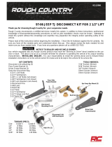
Part # 12280203 - 1961-1965 Ford Falcon HQ Series CoilOver System
Front Components:
12289598 Front TruTurn Kit
12283510 Front CoilOvers
12289100 Front SwayBar
Rear Components:
12287199 Rear 4Link System
12286510 Rear Coilover Instructions
Miscellaneous Components:
85000000 Spanner Wrench
1961-1965 Ford Falcon Coilover
Installation Instructions
Table of contents
Pages 2-24............... TruTurn Front Suspension
Pages 25-31............. Front CoilOvers
Pages 32-36............. Front SwayBar
Pages 37-56............. Rear 4-Link
Pages 57-59............. Rear CoilOvers
Pages 60.................. Shock Adjustment
Mini-Starter required to clear TruTurn Centerlink Adapter (not Included).
The OEM Front Brakes will not work with this kit. (See Page 8 for details)
REV0 9/20/23
This spindle is designed to be used with ridetech hub bearing kit
#12129501. The hub bearing kit utilizies a 3/4” retaining bolt and
t-washers to hold the bearing together. Failure to use the bolt/t-
washer setup will result in immediate bearing failure.
!

2812-482-2932
Installation
Instructions
Recommended Tools
www.ridetech.com
Table of contents
Page 3.............. Major Components
Page 4.............. Upper Control Arm Components
Page 5.............. Lower Control Arm Components
Page 6.............. TruTurn Steering Components
Page 7.............. Hub Bearing & Caliper Bracket Components
Page 8.............. Hardware & Getting Started
Page 9.............. Installing Strut Rod Adapter
Page 10............. Installing Strut Rod Adapter
Page 11-12........ Installing Control Arms
Page 12............. Spindle Installation
Page 13............. Hub Bearing Installation
Page 13-15........ Caliper Bracket Installation
Page 16............. Steering Arm & Stop Installation
Page 17-19........ Installing Idler Arm
Page 19............. Installing Pitman Arm & Centerlink
Page 20-21........ Centerlink Adapter Installation
Page 22-23.........Tie-Rod Assembly and Installation
Page 24............. Alignment
Part # 12289598 - 1961-1965 Ford Falcon Front TruTurn System
1961-1965 Ford Falcon TruTurn System
Installation Instructions
Mini-Starter required to clear TruTurn Centerlink Adapter (not Included).
The OEM Front Brakes will not work with this kit. (See Page 7 for details)
This spindle is designed to be used with ridetech hub bearing kit
#12129501. The hub bearing kit utilizies a 3/4” retaining bolt and
t-washers to hold the bearing together. Failure to use the bolt/t-
washer setup will result in immediate bearing failure.
!

3
www.ridetech.com
Installation
Instructions
Major Components Assembled .....In the box
DRIVER UPPER CONTROL ARM ASSEMBLY
Exploded View on Page 4
DRIVER LOWER CONTROL ARM ASSEMBLY
Exploded View on Page 5
g
STEERING COMPONENTS ASSEMBLY
(drawing shows pin spindle option, this kit includes the hub spindle)
Exploded View on Page 5

4812-482-2932
Installation
Instructions
1
2
7
8
4
9
10
11 15
1112
5
16
17
16 3
18
19
14
6
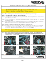
Upper Control Arm Components .....In the box
Driver Side Shown
Item
#Part Number Description QTY
1 90002339 Driver Upper Control Arm (Shown) 1
1 90002340 Passenger Upper Control Arm 1
2 90001589 Heim End 4
3 90009967 Upper Cross Shaft 2
4 70010866 Ball joint Assembly - Proforged # 101-10083 2
5 90002633 Ball joint Spacer 2
6 90002341 3/16” Alignment Shim 2
7 99621002 5/18”-18 x 1 3/4” Hex Bolt 4
8 99623001 5/8” SAE Flat Washer 4
9 99623002 5/8” Split Lock Washer 4
10 99311002 5/16”-18 x 1 1/4” Hex Bolt 6
11 99312003 5/16”-18 Nylok Nut 6
12 99313002 5/16” SAE Flat Washer 12
13 90002067 Shock Bearing Spacers 4

5
www.ridetech.com
Installation
Instructions
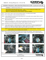
Lower Control Arm Components .....In the box
Item
#Part Number Description QTY
20 90003221 Driver Lower Control Arm (Shown) 1
21 90003222 Passenger Lower Control Arm 1
22 90003223 Strut Rod Frame Bracket Assembly 2
23 90003224 Frame T-Bushing 2
24 90001589 3/4”-16 x 5/8” Bolt Heim End - RH 2
25 90001591 3/4”-16 x 5/8” Bolt Heim End - LH 2
26 99752004 3/4”-16 Jam Nut - RH 4
27 99752006 3/4”-16 Jam Nut - LH 2
28 90002338 Frame Heim Spacer - 1/2” ID x 1.00” Long 4
29 90003225 Strut Rod Bracket Heim Spacer - 5/8” ID x .320” Long 4
30 90002582 Heim End Double Adjuster 2
31 90000898 Lower Ball joint - Proforged # 101-10013 2
Driver Side Shown
37
38
36
32
34
35
33
20 26 30 25
27 23
28
31
22
29
24
26

6812-482-2932
Installation
Instructions
53 59 60
61
41
65 47
71 7068
40
72
52
58
66
57
54
56 55
67
49
70
44 68
45
43
64
62 63
63
50
48
51
65
42
39a
39c
39b
58
TruTurn Steering Components .....In the box
Item # Part Number Description QTY
39 11009311 Ridetech Hub Spindle 1 pr
70015751 Hub Spindle 2
90003535 Steering Arm Threaded Slug 4
99121018 M12-1.5 x 40mm Socket Head Cap Screw 8
40 90002345 Drag Link Stud 2
41 90002351 Inner Tie Rod Stud 2
42 90002346 Tie-Rod Adjuster 2
43 90002347 Driver Steering Arm 1
44 90002348 Passenger Steering Arm 1
45 90002349 Bolt On Steering Stop - Driver 1
46 90002350 Bolt On Steering Stop - Passenger 1
47 90001582 Heim End - 5/8”-18 x 5/8” Bolt - RH Thread 2
48 90001590 Heim End - 5/8”-18 x 5/8” Bolt - LH Thread 2
49 90003219 Outer Tie Rod Stud 2
50 90003220 Outer Tie Rod Spacer - 5/8” ID x .375” BORGESON BOX ONLY 2
51 90002676 Outer Tie Rod Spacer - 5/8” ID x .125” 2
52 90003204 Centerlink Adapter 1
53 90003211 Offset Idler Mount - used with Borgeson Power Steering Box 1
54 90003205 Falcon Centerlink 1
55 90003206 Falcon Pitman Arm 1
56 90003207 Falcon Idler Arm Mount 1
57 90003055 Falcon/Mustang Idler Arm 1
58 12129501 Hub Bearing 2

7
www.ridetech.com
Installation
Instructions
Brake Bracket Components .....In the box
Item
#Part # Description QTY
73 90003539 Caliper Bracket - Driver 1
90003540 Caliper Bracket - Passenger (Not Shown) 1
73
74
75
78
80
3
9
81
76
77
79
Hardware List .....In the box (Kit # 99010227)
Item # Part Number Description QTY
BRACKET TO CALIPER
74 99121005 M12-1.75 X 30mm Hex Bolt 4
75 99123002 M12 Flat Washer 4
SHIM PACK
76 99503018 Shim .016” thick, 1/2” ID 8
77 99503019 Shim .032” thick, 1/2” ID 8
Item # Part Number Description QTY
BRACKET TO SPINDLE
78 99501062 1/2”-13 x 1 1/4” Hex Bolt 2
79 99501075 1/2”-13 x 1 1/4” FHSCS 4
80 99503014 1/2” SAE Flat Washer 2
81 99503017 Shim .063” thick, 1/2” ID 6
Figure 1
This system includes 2015-2023 S550 Mustang rear hubs. If replacing these in the future, the 3/4” retaining bolt
and t-washers must be installed into the new hub. This hardware needs to be torqued to 200 ft-lbs. Failure to do
will result in immediate bearing failure.
!
58a
58b
58c
58d
58
Item # Part Number Description QTY
58 70013663 Hub Bearing (Moog 512517) 1
58a 90003508 Top T-Washer 1
58b 90003509 Bottom T-Washer 1
58c 99751006 3/4”-16 x 3 1/2” Bolt 1
58d 99752005 3/4”-16 Lock Nut 1
If replacing the hubs in the future, the center bolt and t-washers will need
to be installed in the new hub. Torque the 3/4” bolt and nut to 200 ft-lbs.

8812-482-2932
Installation
Instructions
Hardware Shown in Diagrams .....Kit# 99010151
ITEM # QTY
14 99501005 1/2"Ͳ13 x 31/2" bolt GR8 2
15 99502009 1/2"Ͳ13 Nylok Nut GR8 2
16 99503014 1/2" SAE Flat Washer GR8 4
16 99503014 1/2" SAE Flat Washer GR8 8
17 99501050 1/2"Ͳ13 x 21/2" bolt GR8 4
18 99503015 1/2" SPLIT LOCK WASHER, GR8 4
19 99502021 1/2"Ͳ13 HEX Nut GR8 4
26 99752004 3/4Ͳ16 Jam Nut 2
27 99752006 3/4Ͳ16 LH Jam Nut 2
99502017 1/2"Ͳ20 Castle Nut 2
32 99621031 5/8Ͳ18 X 2 1/4" Hex Bolt Gr8 2
33 99622006 5/8Ͳ18 Thin Nylok Nut 2
34 99751005 3/4Ͳ16 X 2" Hex Bolt Gr8 2
35 99752001 3/4Ͳ16 Nylok Nut Gr8 2
36 99501005 1/2Ͳ13 X 3 1/2" Bolt GR8 2
37 99503001 1/2" SAE Flat Washer 4
38 99502001 1/2Ͳ13 Nylok Nut 2
58 99371067 3/8Ͳ16 X 3 1/4" Hex Bolt Gr8 2
59 99373002 3/8" SAE Flat Washer Gr8 2
60 99373006 3/8" Lock Washer 2
Shock To Upper Control Arm
Upper Ball Joint To Spindle
Upper Control Arm To Car
Lower Control Arm To Car
Strut Rod Frame Bracket To Car
Heim End Coupler
Heim End To Strut Rod Frame Bracket
Frame To Idler Mounting Block
ITEM # QTY
59 99373002 3/8" SAE Flat Washer Gr8 2
60 99373006 3/8" Lock Washer 2
61 99371007 3/8Ͳ16 X 1 1/2" Hex Bolt Gr8 2
62 99501026 1/2Ͳ13 X 2 1/4" Hex Bolt GR8 4
63 99503014 1/2" SAE Flat Washer GR8 4
63 99503014 1/2" SAE Flat Washer GR8 2
64 99501052 1/2Ͳ13 X 1" Hex Bolt GR8 2
65 99622003 5/8"Ͳ18 TOP LOCK NU
T
4
66 99800003 5/8"Ͳ18 RH Jam Nut 2
67 99800002 5/8"Ͳ18 LH Jam Nut 2
68 99432005 7/16"Ͳ20 Castle Nut 2
69 99433002 7/16" SAE Flat Washer 2
70 99952002 3/32" Cotter Pin 2
68 99432005 7/16"Ͳ20 Castle Nut 2
69 99433002 7/16" SAE Flat Washer 4
70 99952002 3/32" Cotter Pin 2
71 99622005 5/8"Ͳ18 THIN mechnical locking nut 2
72 99502010 1/2"Ͳ20 Mechanical Locking Nut 2
Steering Linkage
Steering Stop
Draglink Adapter
Idler Mounting Bracket To Mounting Block
Spindle To Steering Arm
Getting Started.........
Congratulations on your purchase of the Ridetech TruTurn System. This System has been designed to give your Falcon
excellent handling along with a lifetime of enjoyment. Some of the key features of the TruTurn System: Ball joint
angles have been optimized for the lowered ride height, eliminated rubber bushings to get rid of bushing deflection
and provide free suspension movement through the entire range of travel. The geometry has been optimized for
excellent handling, driveabilty and minimal bump steer.
Note: These control arms are designed for use with the Ridetech CoilOvers and the MuscleBar swaybar. The factory
shocks and springs or the factory sway bar will not fit these arms.
Mini-Starter required to clear TruTurn Centerlink Adapter (not Included).
Ridetech offers a V8 only crossmember brace to help strengthen the front end of our Falcon. Part # 12289550
Brake Kits
The Hub Bearing used in this kit is a 2015-2022 S550 Mustang hub bearing. It has a 5 on 4 1/2” bolt
pattern for the wheel mounting. The studs of the hub bearing are 14mm.
The Caliper Brackets included in this kit are designed to use 2015-2022 S550 Front rotors and caliper/
caliper brackets. Any brake kit designed for the 2015-2022 Mustang should fit this kit.
1. Remove the entire front suspension from the car including the centerlink, idler arm, and pitman arm. Refer to a
Factory Service Manual for the proper method. The control arms, spindles, and steering linkage will all be replaced
with the TruTurn package.

9
www.ridetech.com
Installation
Instructions
Installing Strut Rod T-Bushing
2. This kit includes a t-bushing for the strut
rod bushing factory hole. The factory hole can
be 2 different diameters depending on the
year of the car. The size of your frame hole
will determine which direction the t-bushing is
installed.
3. Test fit the t-bushing in your car’s strut rod
mount to help determine which direction it
needs to be installed. The t-bushing is installed
from the front side of the car.
4. Insert 3/4”-16 x 2” bolt in the strut rod
frame bracket. The head of the bolt needs
to be on the side of the bracket with the 2
mounting ears.
4.
3.
2.

10 812-482-2932
Installation
Instructions
Installing Lower Control Arm
5. With the 3/4”-16 x 2” bolt installed in the
bracket, attach the bracket to the front heim
of the control arm with the flat side of the
bracket on the same side as the ball joint pin.
The bracket is installed with a 5/8” ID x .320”
spacer on each side of the heim. The spacers
need to be installed with the small outside
diameter against the heim end. Align the holes
of the bracket with the through holes of the
spacers and heim. Install a 5/8”-18 x 2 1/4”
bolt through the aligned holes. Install a 5/18”-
18 thin nylok nut on the threads of the bolt
and torque to 45 ftlbs.
6. Insert the 3/4” bolt of the strut rod adapter
bracket through the center hole of the
t-bushing. The t-bushing and threads of the
bolt should be to the front of the car.
7. Install a 3/4”-16 nylok nut on the threads of
the bolt sticking through the t-bushing. Torque
to 120 ftlbs.
5.
6.
7.

11
www.ridetech.com
Installation
Instructions
Installing Lower & Upper Control Arm
8. Install the 2 aluminum spacers into the
rod end that goes into the factory control arm
pivot. Slip the control arm into the factory
frame mount.
9. Align the factory holes with the control arm
through hole. Install a 1/2” flat washer on
a 1/2”-13 x 3 1/2” hex bolt. Insert the bolt/
washer through the aligned holes. Install a
1/2” flat washer and 1/2”-13 nylok nut on the
threads of the bolt. Torque to 75 ftlbs.
10. Bolt the upper StrongArm to the body
using ½”-13 x 2 ½” bolts, flat washers and lock
washers. The ARROW points to the front of the
vehicle. A shim is supplied and may need to
be installed between the body and the arms to
achieve proper alignment. The arms are preset
at the factory so the alignment should be close,
but the vehicle must be aligned before driving.
Note: The upper arm mounting holes on many
cars have been redrilled 1” lower. This is done
to improve the handling. Our cross shaft has
the drop built into it; make sure to use the
factory mounting holes.
10.
9.
8.

12 812-482-2932
Installation
Instructions
Upper Control Arm & Spindle Installation
11. Install a 1/2” flat washer, 1/2” split lock
washer, and 1/2”-13 nut on the threads of
the 2 bolts sticking through into the engine
compartment. Torque to 75 ftlbs.
12. Install the spindle on the lower ball joint
pin. Torque the ball joint castle nut to 65
ftlbs and tighten to align the cotter pin holes.
Install the cotter pin in the ball joint pin hole
and bend the ends of the cotter pin to hold it
in place. Install the grease zerk supplied with
the ball joint.
13. Install the spindle on the upper ball joint
pin. Torque the ball joint castle nut to 50
ftlbs and tighten to align the cotter pin holes.
Install the cotter pin in the ball joint pin hole
and bend the ends of the cotter pin to hold it
in place. Install the grease zerk supplied with
the ball joint.
11.
12.
13.

13
www.ridetech.com
Installation
Instructions
Hub Bearing Installation
14. The Hub is attached to the spindle using
(4) M12-1.50 x 40 SHCS. Apply RED Loctite to
each of the mounting bolts. Insert them into
the correct holes and Torque to 99 ftlbs.
The steering arms will NOT get
attached to the knuckle until the
brakes are attached. Refer to the
caliper bracket instructions for proper assembly.
14.
STOP
Getting Started.........
These brackets are designed around OEM 2015-2022 S500 Musstang brakes. Aftermarket brakes that are
designed for these cars will also fit this spindle.
Caliper Bracket Installation
Caliper bracket and brake mounting will differ depending on the brake kit being used.
We recommend mocking up the brakes with clean dry threads before applying any loctite to the hardware.
The brake bracket kits include shims for mounting the caliper brackets and calipers. The caliper brackets
will use 1/2” ID .063” thick shims. This kit includes 2 different thicknesses of shims for caliper mounting,
.016” and .032” thick.
The next steps will cover the installation of caliper brackets on the Ridetech spindle. Again, mock up the
brake kits with clean dry threads before using any loctite on the hardware. We are showing the
installation of the caliper bracket with the spindle off the car so it can be shown clearly.
1. 15. Lay a .062” thick, 1/2” ID shim on each of
the caliper brackets (3) mounting holes.
15.

14 812-482-2932
Installation
Instructions
Caliper Bracket Installation
16. The caliper brackets are side specific. They
have a D & P stamped in them. Lay the correct
side caliper bracket on top of the shims, aligning
the mounting holes with the mounting holes
of the bracket. The counter sunk holes should
facing up.
17. Insert a 1/2”-13 x 1 1/4” flat head socket
cap screw in each of the lower mounting holes.
Install a 1/2” flat washer on a 1/2”-13 x 1 1/4”
hex bolt and insert it in the upper mounting
hole. Tighten the hardware to 75 ft-lbs.
18. Install the rotor on the hub. Thread some
lug nuts on the threads of the hub to hold the
rotor tight on the hub.
16.
18.
17.

15
www.ridetech.com
Installation
Instructions
Caliper Bracket Installation
19. The OEM caliper bracket will bolt to the
spindle mount. Install a M12 flat washer on
each of (2) M12-1.75 x 30mm hex bolts. Insert
the bolts through the caliper bracket. Line
the caliper mount up with the hardware and
thread in the bolts.
20. You can use feeler gauges to measure the
distance between the caliper bracket and rotor
to make sure the bracket is centered as much
as possible. If the caliper mount is tighter on
the back side, put shims on the caliper bracket/
spindle. If the caliper bracket is tighter on
the front side, put shims between the caliper
bracket/caliper mount. After you are happy
with the fitment, the hardware will need to red
loctite and torqued. Torque the 1/2” bracket
to spindle hardware to 80 ft-lbs. Torque the
M12 hardware to 69 ft-lbs.
Note: If you are installing aftermarket brakes,
refer to the brake kit instructions for measuring
the caliper placement.
21. Install the brake pads and caliper.
19.
20.
21.

16 812-482-2932
Installation
Instructions
1
2
3
3
A4
4
4
5
Steering Arm Installation
22. The threaded steering arm inserts can
be mounted in 2 different positions. Image
22 illustrates the correct position for the
installation on your vehicle. This position
is what we determined to be the best with
Ridetech suspension.
23. Insert the steering arm slugs into the
spindle with the threads to the bottom of the
spindle,
24. Attach Steering Arm(1) and Steering
Stop(2) to Spindle(A). The Steering Arm and
Stop are attached to the spindle using [2]1/2”-
13 x 2 1/4”(3) & [1] 1/2”-13 x 1”(5) hex bolts
and [3] 1/2” SAE Flat Washers(4). The Steering
Arm is positioned with the Tie Rod End pointing
to the rear of the car and toward the engine.
The Steering Stop is attached to the front
mounting bolt of the steering arm and also
attaches to the inner surface of the spindle in
the top hole. Use the 1/2”-13 x 2 1/4” bolts
with a flat washer in the steering arm. The
1/2”-13 x 1” bolt with a washer, attaches the
top of the steering stop to the inner surface of
the spindle. Use Red Loctite (Supplied in the
Kit) on the bolts and torque to 100 ftlbs.
22.
24.
23.

17
www.ridetech.com
Installation
Instructions
Installing Idler Arm - Stock Steering Box
25. Remove the idler arm that is currently
installed on the car. Your current idler arm may
have 3 mounting holes, but there is a 2 hole
bolt pattern under it. The idler arm supplied
with the kit will use the 2 mounting holes
circled in Image 25.
IF YOU HAVE A BORGESON STEERING BOX
ON YOUR FALCON, SKIP TO STEP 27!
15. Attach the new idler arm using the OEM
hardware. Skip to Step 31.
Installing Idler Arm - Borgeson Power Steering Box
CARS WITH BORGESON POWER STEERING
BOX ONLY!!
27. If using a Borgeson steering box, the
idler arm needs to be lowered to optimize the
steering geometry. The kit includes a spacer
block to do this. The spacer block has 2 sets of
mounting holes, but each set is only threaded
in one side. The idler arm needs to bolt to the
set of holes closest to the edge of the spacer
block. See Image 27.
25.
26.
27.

18 812-482-2932
Installation
Instructions
Installing Idler Arm - Borgeson Power Steering Box
28. The idler mount is attached to the spacer
block using (2) 3/8”16 x 1/2” hex bolts, (2)
3/8” split lock washers, and (2) 3/8” SAE
flat washers. Install a 3/8” split lock washer
followed by a 3/8” SAE flat washer on each
bolt. Line up the idler mount with the bolt
pattern the will position it closest to the edge
of the spacer block. The idler mount needs to
be positioned so the offset positions the pivot
under the spacer block. See Image 28 Line up
the mounting holes with the threaded holes
of the spacer block and thread in the bolt/
washers into each mounting hole. You can
torque these after it is installed on the car.
29. The idler/spacer is attached to the car using
(2) 3/8”-16 x 3 1/4” hex bolts, (2) 3/8” split
lock washers, and (2) 3/8” SAE flat washers.
Install a 3/8” split lock washer followed by a
3/8” SAE flat washer on each bolt. Insert the
bolt/washers into the mounting holes circled in
Step 14. Thread the bolts into the 2 top holes
of the spacer block. Torque all the 3/8” bolts
to 35 ftlbs.
30. Install the idler arm on the idler mount
with the pin pointing up. Position the pin of
the idler to the front of the car before torquing
the castle nut. Torque the castle nut to 35-47
ftlbs and tighten to align the cotter pin hole.
Install the cotter pin and bend the ends.
28.
30.
29.

19
www.ridetech.com
Installation
Instructions
Installing Pitman Arm & Centerlink
31. The TruTurn kit includes a new pitman arm.
A pitman arm puller is necessary to replace
the pitman arm. Remove the OEM pitman
arm using a pitman arm puller. If you do not
have one, they can usually be rented from your
local auto parts store. Install the new pitman
arm using Image 31 as a reference. The large
diameter of the centerlink pin taper should be
down toward the ground. Torque the nut 85-
110 ftlbs.-+
32. Attach the new centerlink in the pitman
arm. The centerlink only has a tapered pin on
one end, it goes into the pitman arm. Torque
the nut of the centerlink pin to 35-47 ftlbs and
tighten to align the cotter pin hole. Install the
cotter pin and bend the ends.
33. The other end of the centerlink will sit
down on the stud of the idler arm. Install the
end of the centerlink on the stud and torque
the castle nut to 25-30 ftlbs. Tighten the nut
to align the cotter pin. Install the cotter pin
and bend the ends.
31.
32.
33.

20 812-482-2932
Installation
Instructions
Centerlink Adapter Installation
34. The studs with the long hex on them will
get installed into the factory centerlink with the
taper going into the centerlink, a 7/16” castle
nut is used to attach it to the centerlink. The
straight shank will point to the front of the car.
Note: It may be necessary to install 7/16”
washers under the castle nut to get the cotter
pin engaged properly.
35. Torque the nuts to 35 ftlbs and tighten as
needed to align cotter pin. Install cotter pin
and bend the ends.
36. The centerlink bracket has one attachment
hole [A] that is slotted. This is to accommodate
the variations in manufacturing and machining
processes, as well as any wear that may have
occurred to the original centerlink over time.
The slot goes on the passenger side centerlink
adapter stud.
A
DRIVERPASSENGER
34.
35.
36.
/