Optional features
Insulated protective cap
200 A insulated protective cap fits over loadbreak reducing tap plug
for dead front shielding.
Capacitive test point
Capacitive test point, on molded T-body, with snap-on cap, provides a
place to mount STVT, STLO and STHI test point faulted circuit indica-
tors.
To order replacement compression connectors and cable adapters
for a PUSH-OP connector, see Catalog CA650006EN, “Deadbreak
Accessories, Tools and Replacement Parts”.
Ordering information
Each PUSH-OP Connector kit contains:
•
Molded Rubber T-body with stainless steel shroud
•
Loadbreak Reducing Tap Plug
•
Cable Adapter
•
Probe
•
Compression Connector
•
Silicone Lubricant
•
Installation Instruction Sheet
•
Copper Alloy Stud
Catalog number selection
Use the following procedure to develop the correct part number for
the desired PUSH-OP kit, based on cable size, conductor size and
desired options.
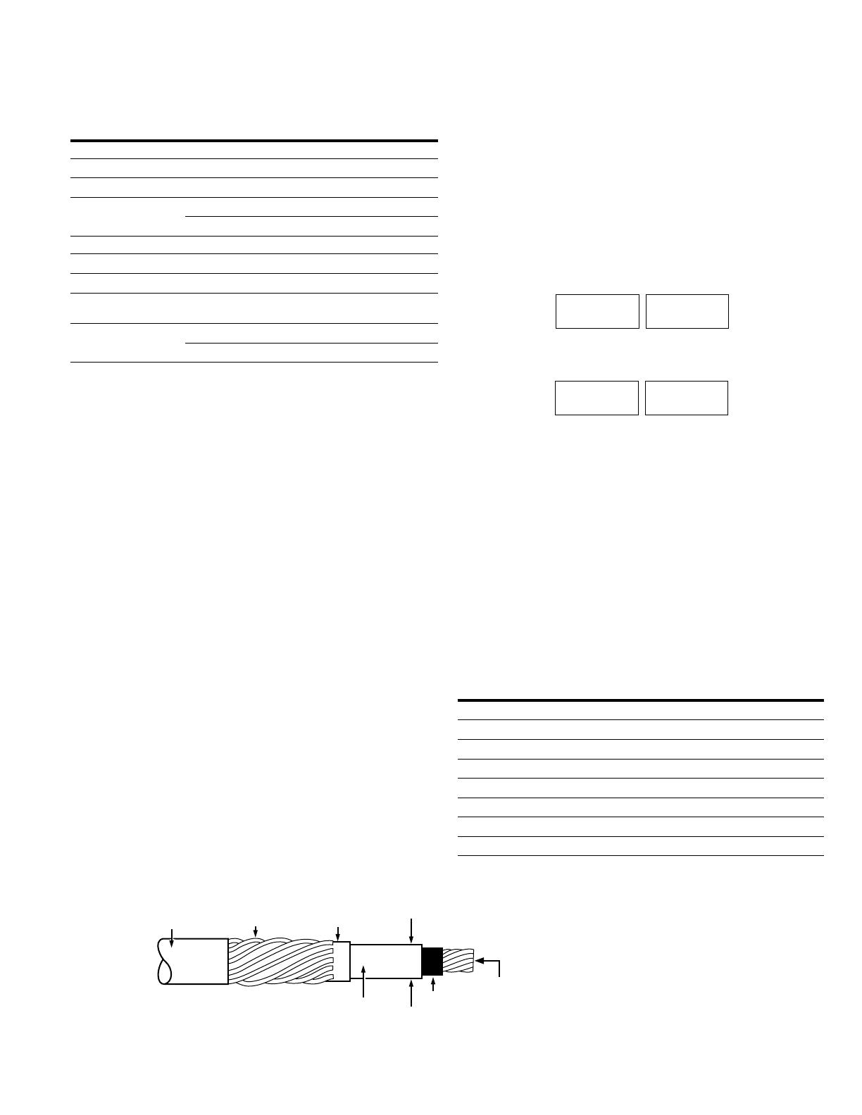
Step 1 – Determine the cable’s diameter over the electrical
insulation as shown in Figure 3 (including tolerances). Then identify a
cable range from Table 3 that brackets the minimum and maximum
insulation diameters. Select the correct CABLE RANGE CODE.
Step 2 – Identify the conductor size and type in Table 4 and select
the CONDUCTOR CODE from the far right column.
Step 3 – For a PUSH-OP kit with a capacitive test point and
protective cap, order:
For a PUSH-OP kit without a capacitive test point or protective cap,
order:
EXAMPLE: To select a PUSH-OP kit without a capacitive test point,
with a protective cap for a 250 kcmil compressed cable with a
nominal insulation diameter of 1.16".
Step 1 – Nominal diameter over the insulation is 1.16" ± .030"
minimum diameter = 1.16 - .030 = 1.13"
maximum diameter = 1.16 + .030 = 1.19"
From Table 3 identify the cable range 1.13" - 1.19" and select the “H”
Cable Range Code.
Step 2 – The conductor size is a 250 kcmil compressed. From Table
4, under the column “Concentric or Compressed”, identify 250 kcmil
and select the “17” conductor code.
Step 3 – Order catalog number:
POP635H17C
Current ratings and characteristics are in ac cor dance with IEEE Std 386™-2006 standard.
* If available system fault current exceeds 10 kA, current limiting fusing must be used upstream.
Otherwise fault close and short time ratings of the 200 A interface will be exceeded.
** Switching rated limited to Single-phase 21.1 kV.
Table 2. Current Ratings and Characteristics
Description Amperes
600 A Interface
Continuous 600 A rms
24 Hour Overload 1,000 A rms
Short Time 40,000 A rms symmetrical for 0.17 s
27,000 A rms symmetrical for 4.0 s
200 A Interface*
Continuous 200 A rms
Switching** 10 operations at 200 A rms at 21.1 kV
Fault Closure 10,000 A rms symmetrical at 36.6 kV for 0.17 s after 10
switching operations
Short Time 10,000 A rms symmetrical for 0.17 s
3,500 A rms symmetrical for 3.0 s
Figure 3. Illustration showing typical construction of medium voltage underground
cable.
OUTER JACKET
CONDUCTOR
INSULATION
CONDUCTOR
SHIELD
METAL NEUTRAL
OR SHIELD
INSULATION
SHIELD
DIAMETER OVER
INSULATION
POP635 TC
CABLE RANGE
CODE
CONDUCTOR
CODE
POP635
CABLE RANGE
CODE
CONDUCTOR
CODE
Table 3. Cable Diameter Range
Inches mm
Cable
Range
Code Inches mm
Cable
Range
Code
0.875-0.985 22.2-25.0 D 1.355-1.520 34.4-38.6 M
0.930-1.040 23.6-26.4 E 1.485-1.595 37.7-40.5 N
0.980-1.115 24.9-28.3 F 1.530-1.640 38.9-41.7 P
1.040-1.175 26.4-29.8 G 1.575-1.685 40.0-42.8 Q
1.095-1.240 27.8-31.5 H 1.665-1.785 42.3-45.3 R
1.160-1.305 29.5-33.1 J 1.755-1.875 44.6-47.9 S
1.220-1.375 31.0-34.9 K 1.845-1.965 46.9-50.0 T
1.285-1.395 32.5-35.4 L 1.960-2.210 49.8-56.1 U
3
Catalog Data CA650052EN
Effective October 2015
600 A 35 kV class PUSH-OP deadbreak connector
www.eaton.com/cooperpowerseries


