6
Catalog Data CA650059EN
Effective July 2022
600 A 25 kV Class T-OP II
deadbreak connector
EATON www.eaton.com
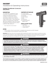
Outer jacket
ConductorInsulation Conductor shield
Metal neutral or shield Insulation shield Diameter over insulation
Figure 3. Typical construction of medium-voltage underground cable
Step 3. Select digit 10 and 11 (optional)
“TC” = T-OP II connector kit with a capacitive test point and
protective cap
“C” = T-OP II connector kit with a protective cap
(no capacitive test point)
Blank = T-OP II connector kit without capacitive test point or
protective cap
Example
Select a T-OP II connector kit without a capacitive test point, with
a protective cap for a 250 kcmil compressed cable with a nominal
insulation diameter of 1.16 inches.
Step 1. Select digits 6 and 7
Nominal diameter over insulation is 1.160 ± 0.030 inches.
Minimum diameter = 1.160 – 0.030 = 1.130 inches.
Maximum diameter = 1.160 + 0.030 = 1.190 inches.
From Table 3, identify the cable range that covers 1.130–1.190 inches
and select the “EE” cable range code.
Step 2. Select digits 8 and 9
The conductor size is 250 kcmil compressed. From Table 4, under
the column “Concentric or compressed,” identify 250 kcmil and
select the “17” conductor code.
Step 3. Select digit 10
A protective cap is needed. Use “C” for digit 10.
The complete catalog number is: TP625EE17C.
Accessories
To order replacement parts and tools, refer to Table 6. To order
replacement compression connectors, shear bolts, and cable
adapters for a T-OP II Connector System, see section CA650007EN
“Deadbreak Accessories, Tools and Replacement Parts.”
Table 6. Replacement parts
Description Catalog number
T-body without test point DT625
T-body with test point DT625T
Loadbreak-reducing tap plug (LRTP) LRTP625
Installation torque tool TQHD625
Operating and test tool OT625
Combination operating and test/torque tool OTTQ625
5/16-inch T-wrench TWRENCH
Copper alloy stud STUD-T
25 kV, 200 A insulated protective cap LPC225
5/16-inch Hex shaft with 3/8-inch socket drive tool HD625