JVC GY HM620E, HM620U Operating instructions

Category
Camcorders
Type
Operating instructions

This manual is also suitable for

.
The specifications and appearance of this product are subject to changes for further improvement
without prior notice.
Please check the latest version of the INSTRUCTIONS from the following Mobile User Guide. You can
also download the PDF from the Mobile User Guide.
This manual provides a brief explanation on
operating this camera recorder. For detailed
operation methods and camera settings,
please refer to the “INSTRUCTIONS”
provided in the supplied CD-ROM or the
following Mobile User Guide.
GY-HM660U/GY-HM660E
GY-HM620U/GY-HM620E
HD MEMORY CARD CAMERA RECORDER
INSTRUCTIONS (BASIC)
.
Mobile User Guide
When you are outside, you can refer to the instructions from your Android phone or iPhone.
http://manual3.jvckenwood.com/pro/mobile/global/
You can view the Mobile User Guide using the browser on your Android phone or iPhone.
IM 1.00 B5A-1234-00
Thank you for purchasing this JVC product.
Before operating this unit, please read the
instructions carefully to ensure the best
possible performance.
In this manual, each model number is
described without the last letter (U/E) which
means the shipping destination.
(U: for USA and Canada, E: for Europe)
Only “U” models (GY-HM660U/GY-HM620U)
have been evaluated by UL.
Please read the following before getting started:
For Customer Use:
Model No.
Serial No.
Enter below the Serial No. which is located
on the body.
Retain this information for future reference.
GY-HM660U/GY-HM620U
TIME CODE
.
1.
Read these instructions.
2.
Keep these instructions.
IMPORTANT SAFEGUARDS
4.
5.
6.
7.
8.
These are general IMPORTANT SAFEGUARDS and certain items may not
apply to all appliances.
3.
FOR USA
9.
10.
11.
12.
13.
CAN ICES-3 A / NMB-3 A
Heed all warnings.
Follow all instructions.
Do not use this apparatus near water.
Clean only with dry cloth.
Do not block any ventilation openings. Install in accordance with the manufacturer’s
instructions.
Do not install near any heat sources such as radiators, heat registers, stoves, or
other apparatus (including amplifiers) that produce heat.
Protect the power cord from being walked on or pinched particularly at plugs,
convenience receptacles, and the point where they exit from the apparatus.
Only use attachments/accessories specified by the manufacturer.
Use only with the cart, stand, tripod, bracket, or table
specified by the manufacturer, or sold with the apparatus.
When a cart is used, use caution when moving the
cart/apparatus combination to avoid injury from tip-over.
Unplug this apparatus during lightning storms or when
unused for long periods of time.
Refer all servicing to qualified service personnel.
Servicing is required when the apparatus has been damaged in any way, such as
power-supply cord or plug is damaged, liquid has been spilled or objects have fallen
into the apparatus, the apparatus has been exposed to rain or moisture, does not
operate normally, or has been dropped.
2
Introduction
Safety Precautions
.
CAUTION
FOR USA AND CANADA
CAUTION:
TO REDUCE THE RISK OF
ELECTRIC SHOCK.
DO NOT REMOVE COVER (OR
BACK).
NO USER-SERVICEABLE PARTS
INSIDE. REFER SERVICING TO
QUALIFIED SERVICE
PERSONNEL.
The lightning flash with
arrowhead symbol, within
an equilateral triangle is
intended to alert the user to
the presence of uninsulated
“dangerous voltage” within
the product’s enclosure that
may be of sufficient
magnitude to constitute a
risk of electric shock to
persons.
The exclamation point within
an equilateral triangle is
intended to alert the user to
the presence of important
operating and maintenance
(servicing) instructions in
the literature accompanying
the appliance.
RISK OF ELECTRIC
SHOCK
DO NOT OPEN
.
This device complies with Part 15 of
FCC Rules. Operation is subject to the
following two conditions: (1) This
device may not cause harmful
interference, and (2) this device must
accept any interference received,
including interference that may cause
undesired operation.
Changes or modifications not
approved by JVC could void the
user’s authority to operate the
equipment. This equipment has been
tested and found to comply with the
limits for a Class A digital device,
pursuant to Part 15 of the FCC Rules.
These limits are designed to provide
reasonable protection against harmful
interference when the equipment is
operated in a commercial
environment.
This equipment generates, uses, and
can radiate radio frequency energy
and, if not installed and used in
accordance with the instructions, may
cause harmful interference to radio
communications. Operation of this
equipment in a residential area is
likely to cause harmful interference in
which case the user will be required
to correct the interference at his own
expense.
3
Introduction
.
POUR CANADA
RISQUE
D’ELECTROCUTION
NE PAS OUVRIR
CAUTION:
The mains plug shall remain readily
operable.
Remove the mains plug immediately if
the camera functions abnormally.
WARNING:
The battery pack, the camera with
battery installed, and the remote control
with battery installed should not be
exposed to excessive heat such as direct
sunlight, fire or the like.
ATTENTION:
POUR EVITER TOUT RISQUE
D’ELECTROCUTION NE PAS
OUVRIR LE BOITER. AUCUNE
PIECE INTERIEURE N’EST A
REGLER PAR L’UTILISATEUR. SE
REFERER A UN AGENT QUALIFIE
EN CAS DE PROBLEME.
ATTENTION
Le symbole de l’éclair à
l’intérieur d’un triangle
équilatéral est destiné à
alerter l’utilisateur sur la
présence d’une “tension
dangereuse” non isolée dans
le boîtier du produit. Cette
tension est suffisante pour
provoquer l’électrocution de
personnes.
Le point d’exclamation à
l’intérieur d’un triangle
équilatéral est destiné à
alerter l’utilisateur sur la
présence d’opérations
d’entretien importantes au
sujet desquelles des
renseignements se trouvent
dans le manuel
d’instructions.
Ces symboles ne sont
utilisés qu’aux Etats-Unis.
.
WARNING: TO PREVENT FIRE OR
SHOCK HAZARD, DO NOT
EXPOSE THIS UNIT TO RAIN OR
MOISTURE.
AVERTISSEMENT : POUR EVITER
LES RISQUES D’INCENDIE OU
D’ELECTROCUTION, NE PAS
EXPOSER L’APPAREIL A LA
PLUIE NI A L’HUMIDITE.
NOTES:
The rating plate and safety caution are
on the bottom and/or the back of the
main unit.
The serial number plate is on the
bottom of the unit.
The rating information and safety
caution of the AC adapter are on its
upper and lower sides.
REMARQUES :
La plaque d’identification et
l’avertissement de sécurité se trouvent
sous l’appareil et/ou au dos.
La plaque du numéro de série est
située sur la partie inférieure de
l’appareil.
Les informations d’identification et
l’avertissement de sécurité de
l’adaptateur secteur sont situés sur ses
côtés supérieur et inférieur.
Caution on Replaceable lithium
battery
The battery used in this device may
present a fire or chemical burn hazard if
mistreated.
Do not recharge, disassemble, heat
above 100°C (212°F) or incinerate.
Replace battery with Panasonic, Sanyo,
Sony or Maxell CR2025.
Danger of explosion or risk of fire if the
battery is incorrectly replaced.
Dispose of used battery promptly.
Keep away from children.
Do not disassemble and do not dispose
of in fire.
4
Introduction
.
When the equipment is installed in a
cabinet or on a shelf, make sure that it
has sufficient space on all sides to allow
for ventilation (10 cm (3-15/16") or more
on both sides, on top and at the rear).
Do not block the ventilation holes.
(If the ventilation holes are blocked by a
newspaper, or cloth etc. the heat may not
be able to get out.)
No naked flame sources, such as lighted
candles, should be placed on the
apparatus.
When discarding batteries,
environmental problems must be
considered and the local rules or laws
governing the disposal of these batteries
must be followed strictly.
The apparatus shall not be exposed to
dripping or splashing and that no objects
filled with liquids, such as vases, shall be
placed on the apparatus.
Do not point the lens directly into the
sun. This can cause eye injuries, as well
as lead to the malfunctioning of internal
circuitry. There is also a risk of fire or
electric shock.
CAUTION!
The following notes concern possible
physical damage to this unit and to the
user.
Carrying or holding this unit by the LCD
monitor can result in dropping the unit,
or in a malfunction.
Do not use a tripod on unsteady or
unlevel surfaces. It could tip over,
causing serious damage to the unit.
CAUTION!
Connecting cables (Audio/Video, etc.) to
this unit and leaving it on top of the TV is
not recommended, as tripping on the
cables will cause the unit to fall, resulting
in damage.
.
When using the AC adapter in
areas other than the USA
The provided AC adapter features
automatic voltage selection in the AC
range from 110 V to 240 V.
USING HOUSEHOLD AC PLUG
ADAPTER
In case of connecting the unit’s power
cord to an AC wall outlet other than
American National Standard C73 series
type, use an AC plug adapter called a
“Siemens Plug” as shown.
For this AC plug adapter, please contact
the local dealers in your area.
Remove the AC adapter from the AC
wall outlet when not in use.
Do not leave dust or metal objects
adhered to the AC wall outlet or AC
adapter (power/DC plug).
Plug Adapter
5
Introduction
.
IMPORTANT (for owners in the U.K.)
Connection to the mains supply in
the United Kingdom.
DO NOT cut off the mains plug from
this equipment.
If the plug fitted is not suitable for the
power points in your home or the cable is
too short to reach a power point, then
obtain an appropriate safety approved
extension lead or contact the local
dealers in your area.
BE SURE to replace the fuse only with
an identical approved type, as originally
fitted, and to replace the fuse cover.
If nonetheless the mains plug is cut off
be sure to remove the fuse and dispose
of the plug immediately, to avoid possible
shock hazard by inadvertent connection
to the mains supply.
If this product is not supplied fitted with a
mains plug then follow the instructions
given below:
DO NOT make any connection to the
Larger Terminal coded E or Green.
The wires in the mains lead are coloured
in accordance with the following code:
If these colours do not correspond with
the terminal identifications of your plug,
connect as follows:
Blue wire to terminal coded N (Neutral)
or coloured black.
Brown wire to terminal coded L (Live) or
coloured Red.
If in doubt consult a competent
electrician.
CAUTIONS:
To prevent shock, do not open the
cabinet. No user serviceable parts
inside.
Refer servicing to qualified personnel.
When you are not using the AC
adapter for a long period of time, it is
recommended that you disconnect the
power cord from AC outlet.
Blue to N
(Neutral) or Black
Brown to L (Live)
or Red
.
FOR EUROPE
This equipment is in conformity with the
provisions and protection requirements of
the corresponding European Directives.
This equipment is designed for professional
video appliances and can be used in the
following environments:
Controlled EMC environment (for
example, purpose-built broadcasting or
recording studio), and rural outdoors
environments.
In order to keep the best performance and
furthermore for electromagnetic
compatibility we recommend to use cables
not exceeding the following lengths:
The inrush current of this apparatus is
4.9 A.
Exclusive
Cable
Exclusive
Cable
Exclusive
Cable
Exclusive
Cable
Coaxial
Cable
Shielded
Cable
Shielded
Cable
Shielded
Cable
Shielded
Cable
Shielded
Cable
DC INPUT 1.8 m
1.4 m
1.2 m
3 m
2 m
3 m
2 m
1 m
1 m
3 m
USB Mini
AV OUT
HDMI
REMOTE
HD/SD SDI
AUX
TC
HEADPHONE
AUDIO INPUT 1/2
Port Cable Length
CAUTION:
Where there are strong electromagnetic
waves or magnetism, for example near a
radio or TV transmitter, transformer,
motor, etc., the picture and the sound
may be disturbed. In such case, please
keep the apparatus away from the
sources of the disturbance.
6
Introduction
.
WARNING
This is a Class A product. In a domestic
environment this product may cause
radio interference in which case the user
may be required to take adequate
measures.
CAUTION:
To avoid electric
shock or damage to
the unit, first firmly
insert the small end
of the power cord into the AC Adapter
until it is no longer wobbly, and then plug
the larger end of the power cord in to an
AC outlet.
FOR EUROPEAN
Dear Customer
This apparatus is in conformance with
the valid European directives and
standards regarding electromagnetic
compatibility and electrical safety.
European representative of
JVC KENWOOD Corporation is:
JVC Technical Services Europe GmbH
Konrad-Adenauer-Allee 1-11
61118 Bad Vilbel
GERMANY
Sehr geehrter Kunde, sehr geehrte
Kundin, dieses Gerät stimmt mit den
gültigen europäischen Richtlinien und
Normen bezüglich elektromagnetischer
Verträglichkeit und elektrischer
Sicherheit überein.
Die europäische Vertretung für die
JVC KENWOOD Corporation ist:
JVC Technical Services Europe GmbH
Konrad-Adenauer-Allee 1-11
61118 Bad Vilbel
DEUTSCHLAND
.
The plastics packaging bags may cause
suffocation when they are covered over the
head. Tear them open, and keep them away
from the reach of infants and children by
ensuring that they are disposed of properly.
.
Battery Pack
The supplied battery pack is a lithium-ion
battery. Before using the supplied battery
pack or an optional battery pack, be sure
to read the following cautions:
To avoid hazards
... do not burn.
... do not short-circuit the
terminals. Keep it away
from metallic objects
when not in use.
When transporting, carry the battery in
a plastic bag.
... do not modify or disassemble.
... do not expose the battery to
temperatures exceeding 60°C (140°F),
as this may cause the battery to
overheat, explode or catch fire.
... use only specified chargers.
Terminals
To prevent damage and prolong
service life
... do not subject to unnecessary shock.
... charge within the temperature range
of 10°C to 30°C (50°F to 86°F). Cooler
temperatures require longer charging
time, or in some cases stop charging
at all. Warmer temperatures prevent
complete charging, or in some cases
stop charging at all.
... store in a cool, dry place. Extended
exposure to high temperatures will
increase natural discharge and
shorten service life.
... keep a 30% battery level if the
battery pack is not to be used for a
long period of time.
... remove from charger or powered unit
when not in use, as some machines
use current even when switched off.
... do not drop or subject to strong
impact.
7
Introduction
.
Para Brasil
Informação sobre eliminação de
baterias
Este produto não deverá ser eliminado
como lixo doméstico em geral.
Devolva a bateria velha ao comerciante
ou para a rede autorizada, para que seja
devolvida ao fabricante ou importador.
A reciclagem e eliminação de lixo em
uma maneira adequada, ajudarão para
preservar recursos, prevenindo, ao
mesmo tempo, contra efeitos prejudiciais
sobre a nossa saúde e o meio ambiente.
o
Para Retirar a Bateria Recarregável
Pressione botão e puxe a bateria para fora.
.
.
.
8
Introduction
Contents
Introduction
Safety Precautions
............................................ 3
Contents ............................................................ 9
Verifying the Accessories .................................. 9
Names of Parts ................................................ 10
Preparations
Adjusting the Grip Belt ..................................... 13
Attaching the Large Eyecup ............................ 13
Charging the Battery ........................................ 13
Opening/Closing the Lens Cover ..................... 14
Attaching/Detaching the Hood ......................... 15
Configuring the Initial Settings ......................... 15
Usable Cards ................................................... 17
Estimated Recordable Time of SD Cards ........ 17
Inserting an SD Card ....................................... 17
Shooting
Basic Shooting Procedures ............................. 20
Miscellaneous Functions for Shooting and
Recording Methods ......................................... 21
Playback
Playing Recorded Clips ................................... 22
Connecting External Devices
Connecting External Monitor ........................... 23
Loading Clips to the PC ................................... 24
Network Functions a
Functions of Network Connection a ............ 25
Others
Menu Screen Hierarchical Chart ..................... 26
Basic Operations in Menu Screen ................... 27
Display Screen ................................................ 28
Status Screen .................................................. 35
Troubleshooting .............................................. 36
Precautions for Proper Use ............................. 38
Specifications .................................................. 42
Software License Agreement .......................... 44
Important Notice concerning the Software ....... 46
Content of this manual
Symbols used
Caution : Describes precautions concerning the
operation of this product.
Memo : Describes reference information, such as
functions and usage restrictions of this
product.
a
: Feature available on
GY-HM660U/GY-HM660E only.
b
: Feature available on
GY-HM620U/GY-HM620E only.
Verifying the Accessories
Verify that the following accessories are included
with the camera recorder before using.
Accessories
Warranty Card (U model only) 1
INSTRUCTIONS (BASIC) 1
Document and Software Disc 1
AC Adapter 1
Power Cord (U model: 1, E model: 2)
Battery 1
Large Eyecup 1
9
Introduction
Names of Parts
.
SERVO MANUAL
ZOOM
REC
H
I
J
K
E GDACBF
FIX VAR OFF
FOCUS ASSIST/1
OIS/2
LOLUX/3
MENU/THUMB
AE LEVEL
FOCUS
ND FILTER
1/64
1/16
1/4
OFF
POWER
MARKER/6
ZEBRA/5
AE LOCK/4
SHUTTER
WHT BAL
CANCEL
PUSH AUTO
IRIS
GAIN
FULL AUTO
PUSH AUTO
PRESET
B
L
M
H
A
ON
OFF
ON
MANU
MODE
OFF
(CHG)
SLOT
A/B
TIME CODE
AUTO
Bottom
A
Built-in Microphone
B
Tally Lamp
C
Microphone Holder
D
Microphone Holder Lock Knob
E
Shoe
F
[FIX/VAR/OFF
] Zoom Speed Switch
G
Accessory Mounting Screw Hole
H
Tripod Mounting Hole
I
[REC] Record Trigger Button
Memo :
0
This button is interlocked with the
[REC] button
R on the grip and the [REC/HOLD] button Z at
the top of the handle.
J
[ZOOM SERVO/MANUAL
] Zoom Operation
Servo/Manual Switch
K
Monitor Speaker
L
Viewfinder
M
Visibility Adjustment Lever
N
Eyecup
O
Battery
P
[x] Headphone Jack (Φ3.5 mm)
Q
[AUX] AUX Input Terminal (Φ3.5 mm)
R
[REC] Record Trigger Button
Memo :
0
This button is interlocked with the
[REC] button
I at the bottom of the lens and the [REC/
HOLD] button Z at the top of the handle.
.
AUX
INPUT2
INPUT1
DEVICE
AV
A
BATT.RELEASE
POWER
/CHG
B
HDMI
REMOTE
DC
HD/SD
SDI
REC
HOST
W
T
REC
HOLD
IN
OUT
TC
L
M
N
O
d
R
S T
X
Z
a
bc
Q
P
U
V
Y
W
S
[C.REVIEW/7
] Clip Review/User 7 Button
T
Zoom Lever at the Grip
U
[TC] TC Input/Output Terminal
V
[IN/OUT] TC IN/OUT Selection Switch
W
Hood Release Button
X
External Microphone Cable Clamp
Y
[INPUT1/INPUT2] Audio Input Terminal 1, 2
(XLR 3-pin x 2)
Z
[REC/HOLD] Record Trigger Button/Lock
Switch
Memo :
0
This button is interlocked with the
[REC] button
R on the grip and the [REC] button I at the
bottom of the lens.
0
The [REC] button R
on the grip and the [REC]
button I at the bottom of the lens will not be
locked.
a
Zoom lever at the Handle
b
Shoulder Belt Mount (x2)
Caution :
0
Be sure to use a shoulder belt with the strength
to
withstand the weight of this camera recorder.
0
If the shoulder belt is not properly attached, the
camera recorder may fall and cause injuries.
Check the instruction manual provided with the
shoulder belt before using.
c
[POWER/CHG] Power/Charging Display Lamp
d
[BATT.
RELEASE] Battery Lock Release Button
10
Introduction
Side Control Panel
.
ND FILTER FOCUS
AE LEVEL
MANU
PUSH AUTO
MENU/THUMB
FOCUS ASSIST/1 OIS / 2 LOLUX / 3
1/64
1/16
1/4
OFF
PRESET
IRIS
GAIN
CANCEL
L
M
H
B
A
WHT BAL SHUTTER
FULL AUTO
MODE
POWER
ON
OFF
(CHG)
ON
OFF
AE LOCK/4 ZEBRA/5 MARKER/6
PUSH AUTO
TIME CODE
AUTO
A
B
C
E
S R Q
O
N
MLKJ
T
D
P
H
I
U
F G
A
[FOCUS AUTO/MANU/
∞] Focus Switch
B
[ND FILTER] ND Filter Switch
C
[PUSH AUTO] Focus Push Auto Button
D
[IRIS] Iris Auto/Manual Selection Button
E
[PUSH AUTO] Iris Push Auto Button
F
[GAIN] Gain Auto/Manual Selection Button / [L/
M/H] Sensitivity Selection Switch
G
[WHT BAL] White Balance Auto/Manual
Selection Button / [B/A/PRESET] Selection
Switch
H
[SHUTTER] Shutter Speed Auto/Manual
Selection Button
I
[y] One Push Auto White Balance Button
J
[FULL AUTO ON/OFF] Full Auto Switch
K
[AE LOCK/4] AE Lock/User 4 Button
L
[ZEBRA/5] Zebra/User 5 Button
M
[MARKER/6] Marker/User 6 Button
N
[MODE] Camera/Media Mode Selection Button
O
[POWER ON/OFF(CHG)] Lock Power ON/OFF
Switch
P
Cross-Shaped Button (JKHI)/Set Button (R)
Q
[LOLUX/3] Low-light Shooting/User 3 Button
R
[OIS/2] Optical Image Stabilizer/User 2 Button
S
[FOCUS ASSIST/1] Focus Assist/User 1 Button
T
[MENU/THUMB] Menu/Thumbnail Button
U
[CANCEL] Cancel Button
SD Slot
.
A
B
C
D
A
SD Card Cover
B
[SLOT A/B] Card Slot Selection Button
C
Card Slot B Status Indicator
D
Card Slot A Status Indicator
Rear Terminal
.
DEVICE
AV
HDMI
REMOTE
DC
HD/SD
SDI
POWER
/CHG
BATT .RELEASE
A
B
OPEN
CLOSE
HOST
AV
DEVICE
HOST
DC
REMOTE
C
D
B
A
E
F
G
A
[DEVICE]
USB Mini Terminal
B
[AV] AV Output Terminal
C
[HD/SD SDI] SDI Output Terminal (BNC)
D
[HDMI] HDMI Output Terminal
E
[HOST] USB Host Terminal a
F
[REMOTE] Remote Terminal
G
[DC] DC Input Terminal
11
Introduction
LCD Monitor
.
MENU/THUMB
CANCEL
CH1
INT
INPUT1
INPUT2
AUTO
MANUAL
CH2
INPUT2
MONITOR
DISPLAY STATUS
INPUT1
PEAKINGLCD BRIGHT
CH2CH1
LINE
MIC
MIC
+48V
CH1
BOTH
CH2
B
C
H I
A
D
FG
E
JKL
N
M
A
LCD Monitor
B
[MENU/THUMB]
Menu/Thumbnail Button
C
LCD Cross-Shaped Button (JKHI)/Set Button
(R)
D
[CANCEL] Cancel Button
E
[CH1/CH2] CH1/CH2 Recording Level
Adjustment Knob
F
[LCD BRIGHT +/-] LCD Display Brightness
Adjustment Button
G
[PEAKING +/-] LCD/VF Contour Adjustment
Button
H
[DISPLAY] Display Button
I
[STATUS] Status Screen Display Button
J
[MONITOR]/[+/-] Audio Monitor Selection
Switch/Volume Adjustment Button
K
[INPUT1/INPUT2] Audio Input Signal Selection
Switch
L
[CH2] CH2 Audio Input Signal Selection Switch
M
[CH1] CH1 Audio Input Signal Selection Switch
N
[CH1/CH2 AUTO/MANUAL] CH1/CH2 Audio
Recording Mode Switch
Lens Section
.
E
CD
A
B
A
Filter Built-In Screw
0
Installable filter types:
Φ72mmP0.75
Memo :
0
Remove
the lens hood when installing the filter.
B
Lens Cover Open/Close Switch
C
Focus Ring
D
Zoom Ring
E
Iris Ring
12
Introduction
Adjusting the Grip Belt
Open
the pad and adjust the position of the grip belt
accordingly.
.
AUX
INPUT2
INPUT1
DEVICE
AV
A
BAT
T.RELEA
SE
POWER
/CHG
B
HDMI
REMOTE
DC
HD/SD
SDI
REC
HOST
Caution :
0
If
the grip is loose, the camera recorder may fall
off resulting in injuries or malfunction.
Attaching the Large
Eyecup
0
Attach the large eyecup (supplied) to prevent
external light from entering the viewfinder
screen and cameraman’s vision.
0
Align and attach to the groove of the eyecup
mounted on the camera recorder.
0
The large eyecup can be attached in any
direction.
.
Large Eyecup (supplied)
Eyecup
Memo :
0
Do not remove the eyecup that is premounted
on the camera recorder.
Charging the Battery
Charge the battery immediately after purchase or
when the battery power is running low.
*
The battery is not charged when purchased.
.
1
2
3
4
4
POWER
/CHG
MODE
POWER
ON
OFF
(CHG)
1
Hold down the lock button (blue) at the
center of the [POWER ON/OFF(CHG)] switch
to set to “OFF(CHG)”.
2
Attach the supplied battery.
Slide it in until you hear a click.
3
Connect the supplied AC adapter to the
[DC]
terminal.
Open the cover of the [DC]
terminal and connect
as shown in the diagram.
4
Connect the AC adapter to a power outlet.
0
The [POWER/CHG] lamp blinks during
charging and will go out after charging is
complete.
0
Remove the AC adapter after charging is
complete.
Memo :
0
Blinking of the [POWER/CHG] lamp during
charging indicates the charge level.
[POWER/CHG] Lamp
Charge Level
Orange blinking
(4 times per second)
Less than 25 %
Orange blinking
(3 times per second)
Less than 50 %
Orange blinking
(2 times per second)
Less than 75 %
Orange blinking
(1 time per second)
Less than 100 %
Light goes out Fully charged
0
You
can charge the battery even when operating
the camera recorder using the AC adapter.
13
Preparations
Removing the Battery
.
1
2
MODE
POWER
ON
OFF
(CHG)
1
Hold down the lock button (blue) at the
center of the [POWER ON/OFF(CHG)] switch
to set to “OFF(CHG)”.
2
While pressing and holding the [BATT.
RELEASE
] button, push up and remove the
battery in the direction of the arrow.
Caution :
0
Do not remove the battery when the [POWER
ON/OFF(CHG)
] switch is “ON”.
0
Do not insert or remove the DC cable when the
battery is in use.
0
Leaving the camera recorder unused with the
battery inside will deplete the battery power
even if you set the
[POWER ON/OFF(CHG)]
switch to “OFF(CHG)”. Remove the battery if
you are not using the camera recorder.
Estimated Charging and Continuous
Operating Times
o Charging Time (supplied SSL-JVC50 battery
pack)
Approx. 4 hrs
*
When the [POWER ON/OFF(CHG)] switch is set
to “OFF(CHG)”
Memo :
0
If
you charge the battery immediately after using
while the battery is still warm, it may not be fully
charged.
0
For
details, refer to the “INSTRUCTIONS” of the
battery.
o Continuous Operating Time (supplied SSL-
JVC50 battery pack)
Approx. 3 hrs a
Approx. 3 hrs 20 mins b
Memo :
0
Actual
operating times may differ depending on
the age of the battery, charging condition, and
operating environment.
0
Operating time is shortened in cold
environment.
0
The operating time may shorten when power
zoom is used, accessories are connected, or
when the LCD monitor is frequently used.
0
For purchase of spare batteries and battery
charger, please contact the local dealers in your
area.
0
Store the battery in a cool and dry place when
not in use. Do not expose the battery to high
temperatures (such as in a car under direct
sunlight). Failure to do so not only shortens the
battery life but also damages the battery.
Opening/Closing the Lens
Cover
Use the lens cover open/close switch to open or
close the lens cover.
Before shooting, open the lens cover.
When
this camera recorder is not in use, close the
lens cover to protect the lens.
.
Caution :
0
Do not press against the lens cover with force.
Doing so may damage the lens or the cover.
14
Preparations
Attaching/Detaching the
Hood
Attaching the Hood
Align the markings on the camera recorder and
hood;
turn the hood in the direction of the arrow until
it is locked.
.
Detaching the Hood
0
Remove the hood when attaching a filter,
teleconverter
or wide converter to the front of the
lens.
0
While pressing the hood release button, turn the
hood in the direction of the arrow (anti-
clockwise) to remove it.
.
Configuring the Initial
Settings
When
the power is first turned on, the Initial Setting
screen for performing the initial settings in the
camera recorder appears.
Set the date/time of the built-in clock in the [Initial
Setting] screen.
All operations are disabled until initial settings are
complete.
.
MODE
POWER
ON
OFF
(CHG)
AE LEVEL
MENU/THUMB
CANCEL
MENU/THUMB
CANCEL
Memo :
0
It
is recommended to use the AC adapter as the
power supply.
0
Be sure to close the lens cover.
1
Hold down the lock button (blue) at the
center of the [POWER ON/OFF(CHG)] switch
to set to “ON”.
A language selection screen appears.
0
For U models
.
0
For E models
.
15
Preparations
Memo :
0
The menus and messages on the screen of the
LCD monitor or viewfinder are displayed in the
selected language.
2
Select a language using the cross-shaped
button (JK), and press the Set button (R).
The Initial Setting screen appears.
.
3
Ensure that the lens cover is closed, and
press the Set button (R).
0
Self-diagnosis starts.
0
A progress bar appears, and “Complete
Diagnosis
” appears when the diagnosis is
complete.
.
Memo :
0
It takes about 6 minutes to complete the
diagnosis. During the diagnosis, do not operate
or turn off the camera recorder.
4
Press the Set button (R) after confirming
the exit screen.
The [Initial Setting] screen appears.
0
For U models
.
0
For E models
.
Memo :
0
The
[Initial Setting] screen appears when the
power is turned on for the first time and when the
power is turned on after the built-in battery is fully
discharged.
0
The configured date/time data is saved in the
built-in
rechargeable battery even if the power is
turned off.
5
Set the time zone and date/time.
A
Move the cursor with the cross-shaped button
(HI) and select the setting item.
B
Change the values with the cross-shaped
button (JK).
6
Press the Set button (R) after setting is
complete.
The clock is set to 0 seconds of the input date/
time.
Memo :
0
The
configured date/time data can be displayed
on the LCD monitor and viewfinder and be
recorded to the SD card.
0
The value of the year can be set in the range of
“2000” to “2099”.
16
Preparations
Usable Cards
Use a Class 6/10 SD card.
Memo :
0
Depending on the recording format, SD card
with Class 4 or higher performance can also be
used.
0
To use an SDHC card, set
[4GB File
Spanning(SDXC)] to “On”.
Caution :
0
Using cards other than those from Panasonic,
TOSHIBA or SanDisk may result in recording
failure or data loss.
Estimated Recordable
Time of SD Cards
The estimated recordable time is only a guide.
Differences may occur depending on the SD card
in use and the battery condition.
QuickTime/MP4/MXF
MPEG2/HD
SP HQ
720p 1080i 720p/1080i/1080p
4 GB 22 17 12
8 GB 45 35 25
16 GB 90 70 50
32 GB 180 140 100
64 GB
(SDXC)
360 280 200
128 GB
(SDXC)
720 560 400
(Unit: minute)
AVCHD
HQ HQ SP LP EP
1080p 1080i
4 GB 16 19 25 46 82
8 GB 33 39 50 95 168
16 GB 67 78 100 190 336
32 GB 135 156 200 380 672
64 GB
(SDXC)
270 312 400 760 1344
128 GB
(SDXC)
540 624 800 1520 2688
(Unit: minute)
QuickTime
H.264/HD H.264/SD H.264/Web
XHQ UHQ - HQ LP
1080i/1080p 480i/576i 960p 480p
4 GB 9 12 47 130 285
8 GB 18 25 95 270 580
16 GB 36 50 190 540 1160
32 GB 72 100 380 1080 2320
64 GB
(SDXC)
145 200 760 2160 4720
128 GB
(SDXC)
290 400 1520 4320 9440
(Unit: minute)
Memo :
0
If the SD card contains files recorded by devices
other than this camera recorder or files that are
saved from a PC, the recordable time may be
shorter or data may not be properly recorded.
0
The number of clips that can be recorded to one
SD card on this camera recorder for each file
format is restricted.
Up to 600 clips can be recorded for the
“QuickTime” file format and 4000 clips for the
“AVCHD” file format. When the maximum
number of clips is reached, the remaining space
is displayed as “0 min” regardless of the
estimated recordable time, and no further
recording can be made.
Inserting an SD Card
This camera recorder comes with two card slots
(Slot A and B) for video/audio recording and
playback.
.
1
2
3
1
A
B
2
1
Open the SD card cover.
2
Insert an SD card with the notched corner
pointing up.
The status indicator of the card slot to which the
card was inserted lights up in red.
3
Close the SD card cover.
17
Preparations
Formatting (Initializing) SD Cards
When the following cards are inserted, [!FORMAT]
appears at the remaining media display area.
Format the card using the camera recorder menu.
0
Unformatted SD cards
0
SD cards formatted under different
specifications
Caution :
0
Be sure to format the SD card on this camera
recorder.
SD cards formatted on a PC and other
peripheral equipment cannot be used on this
camera recorder.
0
[!RESTORE] appears at the remaining media
display area when an SD card that requires
restoring is inserted.
1
Select [System] B [Media] B [Format
Media]
.
2
Select the slot of the SD card to be
formatted and press the Set button (R).
.
2
3
The status of the selected SD card appears.
4
Select [Format] and press the Set button
(R).
.
4
5
Formatting starts.
.
6
Formatting is complete.
When formatting is complete, “Complete” appears
and the camera recorder returns to the [Format
Media] screen.
Memo :
0
During formatting, menu operation is
unavailable but you can start recording.
However, this is only available when a
recordable SD card is inserted in the other slot.
0
Formatting
cannot be performed in the following
cases.
0
Recording is in progress on the SD card to be
formatted.
0
SD card is not inserted.
0
Write-protect switch of the SD card is set (z
is displayed).
Caution :
0
If you format the SD card, all data recorded on
the card, including video data and setup files,
will be deleted.
18
Preparations
Clips Recorded to SD Cards
Folders in the SD Card
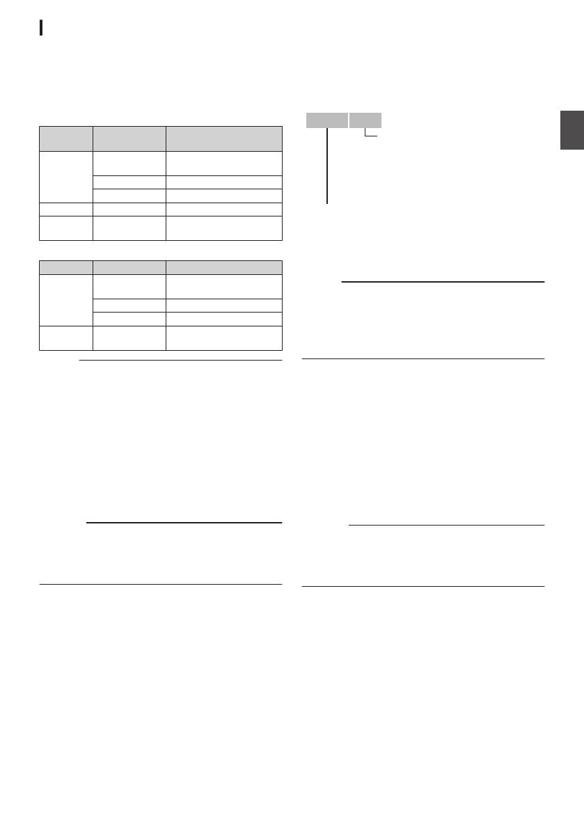
Images recorded are sorted into the respective
folders according to the menu settings below.
*
Select which folder to record to from the menu.
o
a
System
WFormat/
YFormat
Record Folder
HD QuickTime
(MPEG2)
DCIM or PRIVATE/JVC/
CQAV*
MP4(MPEG2) PRIVATE/JVC/BPAV
MXF(MPEG2) PRIVATE/JVC/CMAV
HD/Web AVCHD PRIVATE/AVCHD
HD/SD/Web
QuickTime(H.264)
DCIM or PRIVATE/JVC/
CQAVC*
o
b
System Format Record Folder
HD QuickTime
(MPEG2)
DCIM or PRIVATE/JVC/
CQAV*
MP4(MPEG2) PRIVATE/JVC/BPAV
AVCHD PRIVATE/AVCHD
HD/SD
QuickTime(H.264)
DCIM or PRIVATE/JVC/
CQAVC*
Memo :
0
When [System] is set to “
HD+Web”, web files
(MOV format) will be recorded in the [DCIM]
folder. a
0
By formatting (initializing) the SD card from the
[Format Media] menu on the camera recorder,
folders required for recording in the current
[System] settings will be generated.
0
When the [
System] settings and
[QuickTime(MPEG2)] settings are changed,
folders required for recording in those settings
will be automatically generated.
Caution :
0
When
a clip inside the folder is moved or deleted
using the Explorer (Windows) or Finder (Mac),
recording to the SD card may fail if formatting
(initializing) of the card is not performed.
Clip (Recorded Data) and Clip Name
0
When recording is stopped, the images, audio
and accompanying data which are recorded
from start to stop are recorded as one “clip” on
the SD card.
0
An 8-character clip name is automatically
generated for the recorded clip.
(“Clip Name Prefix
” + “Clip Number”)
0
When [Main Menu] B [System] B [Record Set]
B [Record Format
] B [WFormat] is set to
“AVCHD”, the clip name generated consists of
only the Clip Number (5-digit number).
Example: In the case of QuickTime/MP4
.
ABCG0001
This is set to “xxxG” (“xxx” denotes the last 3
digits of the serial number) by default.
Clip Name Prefix (any four alphanumeric characters)
The Clip Number can be reset in
the menu.*
A number in automatic
ascending order is assigned in
the recording order.
Clip Number
* [Clip Set] B [Reset Clip Number]
Memo :
0
Before recording starts, you can set any
characters for the clip name prefix by using
[Main
Menu] B [System] B [Record Set] B [Clip
Set] B [Clip Name Prefix].
0
Changes cannot be made after recording.
Recorded Clips
0
The
recorded materials may be split into several
files but they can be played back continuously
on the camera recorder.
0
Clips may be recorded across the two SD cards
in card slots A and B depending on the recording
time of the clip.
0
When copying videos in MP4 file format to a
HDD using a PC, it is recommended to use [JVC
ProHD Clip Manager Software], which is found
in the supplied disc, to maintain continuity.
Caution :
0
A clip recorded across several cards cannot be
played
back continuously. Continuous playback
is only possible when the recording is made on
one card.
19
Preparations
Basic Shooting
Procedures
Preparations
.
3
1
MODE
POWER
ON
OFF
(CHG)
4
2
4
1
Supply battery or AC adapter power to the
camera recorder.
2
Insert an SD card.
3
Turn on the power of the camera recorder.
Hold down the lock button (blue) at the center of
the [POWER ON/OFF(CHG)] switch to set to
“ON”. The camera recorder starts up in Camera
mode and is ready for recording.
4
Adjust the angle of the LCD monitor and
viewfinder.
5
Configure [System], [Format], [Resolution]
and [
Frame & Bit Rate] in [Main Menu] B
[System] B [Record Set] B [Record
Format].
0
You
can select the definition of the recorded
videos (HD, SD or Web a), file format for
recording/playback, and the video recording
format on this camera recorder.
0
Press the [MENU/THUMB] button on the
LCD monitor to display the menu screen on
the LCD monitor and viewfinder.
0
The following setting values are the factory
defaults.
[System]: HD
[Format]
: QuickTime(MPEG2)
[Resolution]: 1920x1080
[Frame & Bit Rate]: 60i(HQ) (U model) or
50i(HQ) (E model)
Shooting
1
Configure the video and audio input
settings.
You have to configure video settings such as
brightness adjustment (iris, gain, shutter) and
white balance adjustment in order to start
shooting. You also have to adjust the audio
input settings and audio recording level for
audio recording.
0
Adjusting the Brightness
0
Adjusting the White Balance
0
Adjusting Audio Input Settings and
Recording Level
2
Press the [
REC] button to start recording to
the SD card.
This camera recorder has three [REC]
buttons.
Any of the [REC] buttons can be used to start/
stop recording by default.
The tally lamp lights up in red during recording.
0
Zoom Operation
0
Adjusting the Focus
Memo :
0
If
both the slots are loaded with recordable cards
in the factory default, pressing the [REC] button
starts recording only to the media in the selected
slot.
When [Main Menu] B [System] B [Record Set]
B [Slot Mode] is set to “Dual”, recording can be
performed simultaneously to the cards in both
the slots.
0
The tally lamp can be turned off in
[System] B
[Tally Lamp].
3
Check the most recently captured images.
0
Press the
[C.REVIEW/7] button on the lens
to activate the Clip Review function. The
most recently captured images are played
back on the LCD monitor and viewfinder
screen.
0
After playback, the camera recorder returns
to standby mode (STBY).
Memo :
0
[Clip Review
] is assigned to [C.REVIEW/7]
button in factory default.
0
[Clip
Review] can also be assigned to other user
buttons.
20
Shooting
  • Page 1 1
  • Page 2 2
  • Page 3 3
  • Page 4 4
  • Page 5 5
  • Page 6 6
  • Page 7 7
  • Page 8 8
  • Page 9 9
  • Page 10 10
  • Page 11 11
  • Page 12 12
  • Page 13 13
  • Page 14 14
  • Page 15 15
  • Page 16 16
  • Page 17 17
  • Page 18 18
  • Page 19 19
  • Page 20 20
  • Page 21 21
  • Page 22 22
  • Page 23 23
  • Page 24 24
  • Page 25 25
  • Page 26 26
  • Page 27 27
  • Page 28 28
  • Page 29 29
  • Page 30 30
  • Page 31 31
  • Page 32 32
  • Page 33 33
  • Page 34 34
  • Page 35 35
  • Page 36 36
  • Page 37 37
  • Page 38 38
  • Page 39 39
  • Page 40 40
  • Page 41 41
  • Page 42 42
  • Page 43 43
  • Page 44 44
  • Page 45 45
  • Page 46 46
  • Page 47 47
  • Page 48 48

JVC GY HM620E, HM620U Operating instructions

Category
Camcorders
Type
Operating instructions
This manual is also suitable for

Ask a question and I''ll find the answer in the document

Finding information in a document is now easier with AI