Page is loading ...

1
PACKAGING CONTENTS /CONTENU DE L’EMBALLAGE/CONTENIDO DEL PAQUETE
Instruction Manual/Instrucciones/Directives
Questions?/¿Preguntas ?/Questions ? 1-800-334-6871 www.eaton.com/lighting
INSTALLATION INSTRUCTIONS
1. Turn off the power at the main fuse/breaker box.
Carefully open carton, remove fixture and end caps
from carton.
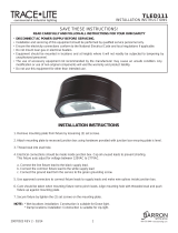
2. To remove the channel cover with LED’s from the
main channel body squeeze beneath the embossed
locking tabs on the main channel body and lift on
the channel cover with LED’s. Do this for all 6
locking tab locations (Fig. 1). The channel cover
with LED’s can be placed in safe location until
fixture is mounted.
3. Remove appropriate knockout(s) for power
supply wiring. To remove, simply place a flathead
screwdriver on the knockout and strike it sharply
with a hammer (Fig. 2). The slug may then be
removed with pliers.
4. Locate the white driver disconnect inside the main
channel and pull out the half with no wires attached
(Fig. 3).
5. Prepare the supply wires.
A. Wiring must comply with all applicable electrical
codes.
B. Strip wire to 3/8” (9, 5 mm).
C. Grip black supply wire firmly and push conductor
into port marked with black circle and letter “B”
on the connector (Fig. 4).
D. Grip white supply wire firmly and push conductor
into port with white circle and letter “W” on the
connector (Fig. 4).
E. Grip ground supply wire firmly and push
conductor into port with green circle on the
connector (Fig. 4).
6. Attach junction box cover plate and pull connector
through junction box (Fig. 4).
Note: See row mounting section if row mounting
before continuing to step 7.
ITEMS REQUIRED
(Purchase separately)
• Stud mount (2) 1 1/2 in. long #8 or larger wood screws and a #10 flat washer
• Drywall mount (2) 3 in. long 3/16” or larger diameter toggle bolt and #10 flat washer
(if joist cannot be located)
• Phillips screwdriver
• Flat head screwdriver
• Pliers
• Hammer
• Safety glasses
• Ladder
Note: This product is intended for either single mount or continuous row applications.
IMPORTANT SAFETY INSTRUCTIONS
When using product, basic precautions should always be followed, including the following:
• Read and follow these instructions.
• Heed all warnings, including below warnings AND those included on product.
• Save these instructions and warnings.
• Risk of fire/electric shock.
• Ground fixture to avoid potential electric shock.
• Turn off the power at fuse or circuit breaker box before installation and maintenance.
• Edges may cut. Handle with care.
CAUTION
• Connect model: 4SLSTP4040DD-120V, 4SLSTP2040DD-120V, 2SLSTP2040DD-120V,
2SLSTP1040DD-120V fixture to a 120 volt, 60 Hz power source. Any other connection
voids the warranty.
• Connect model: 4SLSTP4040DD-UNV, 4SLSTP2040DD-UNV may be connected to 120-
277 volt, 60 Hz power source.
• Fixture should be installed by persons with experience wiring or by a qualified
electrician. The electrical system, and the method of electrically connecting the fixture
to it, must be in accordance with the National Electrical Code and local building codes.
ENGLISH
A. Fixture channel
Canal de la luminaria
Canal du luminaire
B. Decorative end caps
Tapas decorativas
Embouts décoratifs
4SLSTP4040DD-120V
4SLSTP4040DD-UNV
4SLSTP2040DD-120V
4SLSTP2040DD-UNV
WARNING
Fig. 1
Fig. 2
2SLSTP2040DD-120V
2SLSTP1040DD-120V
Fig. 3
Fig. 4
Black
White
Ground
D. Mounting screws
Tornillos de montaje
Vis de montage
C. Junction box cover plate
Placa de cubierta de la caja de derivación
Plaque de recouvrement de la boîte de jonction
E. Channel cover with LED’s
Cubierta del canal con luces LED
Couvercle du canal avec DEL
F. Lens assembly
Unidad de la lente
Ensemble de la lentille

2
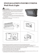
7. Locate power supply wires from the junction box and pull them through the knockout that
has been removed on the main channel body so that the wires and disconnect are inside
the housing channel (Fig. 5).
8. Attach main housing channel to ceiling or wall using #8 or larger diameter wood screws
plus #10 flat washer for stud mount or 3/16” diameter or larger toggle bolt plus #10 flat
washer for drywall mounting. The spacing for mounting brackets is 37-3/16” for 4’ fixture
or 14 9/16” for 2’ fixture. (Fig. 6 & 7).
Note: 2’ fixture mounting hole pattern is not symmetric.
9. Fully reconnect the quick disconnect by pushing the mating ends together (Fig. 8).
10. Locate the channel cover with LEDs and provided lead wires to make connections to the
driver output wires and ground wire. To properly engage wires, firmly push wire leads
into the orange in-line connector attached to the driver output leads. Connect the black
lead on the cover with the black lead on the driver. Then, connect the red lead on the
cover with the red lead on the driver. Lastly, connect the green lead on the cover with the
green ground lead on the housing channel. For fixtures with 2 drivers connect the second
set of black and red wires to the Channel cover with LED’s. Black to black and red to red
(Fig. 9A, 9B & 9C).
Note: For dimming see Installing Dimmer Instruction Section.
11. Tuck all the excess supply wire, orange inline connectors, and the quick disconnect back
into the main channel housing.
12. Mechanically attach the Channel cover with LED’s back to the housing channel by sliding
the Channel cover with LED’s holes onto the locking tabs on the main housing channel
(Fig. 10) Remove protective film from the lens.
13. Optional: Attach decorative end caps by placing the end cap’s locking tabs over the ends
of the fixture and sliding towards the center of the fixture until both the locking tabs snap
into end cap holes on main housing (Fig. 11A & 11B).
Note: Decorative end caps cannot be placed between two fixtures which have been
row mounted together. For row mounting decorative end caps can only be placed on
far ends of fixture.
ROW MOUNTING
1. For row mounting locate the metal end plate at the end of the fixture of the main channel
body which you plan to remove. Remove the endplate screw from the metal endplate
(Fig. 12). Repeat for adjacent fixture.
2. Squeeze the main channel housing to release the locking tabs on the metal end plate
and remove the metal end plate from main channel housing (Fig. 13). Repeat for
adjacent fixture.
3. Using one of the metal end plates which you just removed break away the row mounting
tab by bending the end plate. A few maximum bends may be required to completely
break away the tab (Fig. 14A).
Fig. 5
Fig. 6
Fig. 7
Fig. 9B
Fig. 9A
Fig. 11A
Fig. 8
Fig. 10
Fig. 11B
Fig. 13
Fig. 14A
Fig. 12
Joist Mount
Drywall
Detached
Use Large
Hole Only
Locking
Tabs
End Cap
Hole
Bending End Plate
Endplate
Screw
Fig. 9C
Red
Red
Black
Black
Green
Green
Note: Mounting hole pattern
not symmetric
4 ft. Striplight
2 ft. Striplight
37-3/16 in. (944 mm)
8 13/16 in.
(223.50 mm)
5 3/4 in.
(146.50 mm)
14 9/16 in. (370 mm)

3
4. Using the row mounting tab from the metal end plate insert it into the slots provided at
the end of the main channel housing (Fig. 14B). Ensure locking tabs are facing the
locking tab hole provided in the main housing body. Slide row mounting tab into slot until
an audible click is heard (Fig. 14C).
5. Mount the first fixture with row mounting tab following steps 7-12 above.
6. To install second fixture slide fixture over row mounting tab (Fig. 14C) and follow steps
7-12 above.
INSTALLING DIMMER
(For a fixture containing (1) 120/277V Driver)
• Using the wire termination provided on the dimming lead, combine the positive lead
from the dimmer with the positive lead (violet) connected to the dimming port (DIM +)
of the driver.
• Combine the negative lead from the dimmer with the gray negative lead connected to
the (DIM -) dimming port of the driver using the wire termination that is fastened to the
end of the gray dimming lead..
(For a fixture containing (2) 120/277V Drivers)
• The dimming leads for each driver come connected together using a wire termination.
• To add dimming capability, untwist wire termination for the violet positive dimming
leads which are both connected to the (DIM +) driver ports. Combine the positive lead
fromthe dimmer, and connect all three positive leads together using the wire
termination.
• Untwist wire termination for the gray negative dimming leads which are both
connected to the (DIM -) driver ports. Combine the negative lead from the dimmer, and
connect all three negative leads together using the wire termination.
(For a fixture containing (1) 120V Driver. Wire per dimmer manufacturer’s instructions)
• See www.eaton.com/lighting/brands/metalux/strips.html for a listing of dimmers that
are compatible with the SLSTP series product.
ENERGY STAR
®
(Para 4SLSTP4040DD-120 V, 4SLSTP2040DD-120 V, 2SLSTP2040DD-120 V y
2SLSTP1040DD-120 V solamente)
5-YEAR LIMITED WARRANTY
THE FOLLOWING WARRANTY IS EXCLUSIVE AND IN LIEU OF ALL OTHER WARRANTIES,
WHETHER EXPRESS, IMPLIED OR STATUTORY INCLUDING, BUT NOT LIMITED TO, ANY
WARRANTY OF MERCHANTABILITY OR FITNESS FOR ANY PARTICULAR PURPOSE.
Eaton’s Cooper Lighting Business (“Eaton’s Cooper Lighting”) warrants to customers that, for
a period of five years from the date of purchase, Eaton’s Cooper Lighting Business (“Eaton’s
Cooper Lighting”) products will be free from defects in materials and workmanship. The
obligation of Eaton’s Cooper Lighting Business (“Eaton’s Cooper Lighting”) under this warranty
is expressly limited to the provision of replacement products. This warranty is extended only
to the original purchaser of the product. A purchaser’s receipt or other proof of date of original
purchase acceptable to Eaton’s Cooper Lighting Business (“Eaton’s Cooper Lighting”). This
is required before warranty performance shall be rendered. This warranty does not apply
to Eaton’s Cooper Lighting Business (“Eaton’s Cooper Lighting”) products that have been
altered or repaired that have been subjected to neglect, abuse, misuse or accident (including
shipping damages). This warranty does not apply to products not manufactured by Eaton’s
Cooper Lighting Business (“Eaton’s Cooper Lighting”) which have been supplied, installed,
and/or used in conjunction with Eaton’s Cooper Lighting Business (“Eaton’s Cooper Lighting”)
products. Damage to the product caused by replacement bulbs or corrosion or discoloration of
brass components are not covered by this warranty.
LIMITATION OF LIABILITY:
IN NO EVENT SHALL EATON’S COOPER LIGHTING BUSINESS (“EATON’S COOPER LIGHTING”)
BE LIABLE FOR SPECIAL, INDIRECT, INCIDENTAL, OR CONSEQUENTIAL DAMAGES
(REGARDLESS OF THE FORM OF ACTION, WHETHER IN CONTRACT, STRICT LIABILITY, OR IN
TORT INCLUDING NEGLIGENCE), NOR FOR LOST PROFITS; NOR SHALL THE LIABILITY OF
EATON’S COOPER LIGHTING BUSINESS (“EATON’S COOPER LIGHTING”) FOR ANY CLAIMS
OR DAMAGE ARISING OUT OF OR CONNECTED WITH THESE TERMS OR THE MANUFACTURE,
SALE, DELIVERY, USE, MAINTENANCE, REPAIR OR MODIFICATION OF COOPER LIGHTING
PRODUCTS, OR SUPPLY OF ANY REPLACEMENT PARTS THEREFORE, EXCEED THE PURCHASE
PRICE OF EATON’S COOPER LIGHTING BUSINESS (“EATON’S COOPER LIGHTING”) PRODUCTS
GIVING RISE TO A CLAIM. NO LABOR CHARGES WILL BE ACCEPTED TO REMOVE OR INSTALL
FIXTURES.
To obtain warranty service, please contact Eaton’s Cooper Lighting Business (“Eaton’s Cooper
Lighting”), at 1-800-334-6871, press option 2 for Customer Service, or via e-mail Consumer-
[email protected] and include the following information:
• Name, address and telephone number
• Date and place of purchase
• Catalog and quantity purchase
• Detailed description of problem
All returned products must be accompanied by a Return Goods Authorization Number issued
by the Company and must be returned freight prepaid. Any product received without a Return
Goods Authorization Number from the Company will be refused. Eaton’s Cooper Lighting
Business (“Eaton’s Cooper Lighting”) is not responsible for merchandise damaged in transit.
Repaired or replaced products shall be subject to the terms of this warranty and are inspected
when packed. Evident or concealed damage that is made in transit should be reported at once
to the carrier making the delivery and a claim filed with them.Reproductions
of this document without prior written approval of Eaton’s Cooper Lighting Business (“Eaton’s Cooper Lighting”)
are strictly prohibited.
For assistance, call 1-800-334-6871 or e-mail us at [email protected]
Printed in China
ARTÍCULOS NECESARIOS
(se compran por separado)
• Destornillador en cruz (Phillips)
• Destornillador de cabeza plana
• Alicates
• Martillo
• Gafas de seguridad
• Escalera
• Montaje en pasador (2) 1 1/2 pulg. De largo # 8 o más grande de madera tornillos y
una arandela # 10 plana
• Montaje en paneles de yeso con dos (2) pernos de la pieza basculante de 3 pulg. de
largo de 3/16” de diámetro o más y una arandela plana n. ° 10 (en caso de no poder
ubicar la viga)
Nota: Este producto no tiene como fin su aplicación continua en hileras.
INSTRUCCIONES IMPORTANTES DE SEGURIDAD
• Lea y siga estas instrucciones.
• Tenga en cuenta todas las advertencias, incluyendo las advertencias a continuación
Y aquellas incluidas en el producto.
• Guarde estas instrucciones y advertencias.
• Riesgo de fuego/descarga eléctrica. Si no está capacitado, consulte a un electricista.
• Conecte a tierra el accesorio para evitar una posible descarga eléctrica.
• Desconecte el suministro eléctrico en la caja de fusibles o interruptor de circuito antes
de la instalación y el mantenimiento.
• Las orillas pueden cortar. Manipúlela con cuidado.
PRECAUCION
• Modelo de conexión: Luminaria 4LWP3940ND-120 V o 2SLWP2040ND- 120 V a una
fuente de alimentación de 120 voltios, 60 Hz. Cualquier otro tipo de conexión será
causal de anulación de la garantía.
• Modelo de conexión: 4SLWP4040ND-UNV-120 V/277 V se puede conectar a una fuente
de alimentación de 120-277 voltios, 60 Hz.
• El accesorio debe ser instalado por personas con experiencia en cableado
doméstico o por un electricista calificado. El sistema eléctricoy el método de conexión
eléctrica del accesorio debe cumplir con el Código eléctrico nacional y los códigos
locales sobre edificios.
INSTRUCCIONES PARA LA INSTALACIÓN
1. Desconecte la alimentación en el fusible o en
la caja del disyuntor. Abra con cuidado la caja,
retire la luminaria y las tapas del interior.
2. Para quitar la cubierta del canal con luces LED
del cuerpo del canal principal, apriete debajo de
las lengüetas de bloqueo en el cuerpo del canal
principal y levante la cubierta con luces LED.
Hágalo para las 6 ubicaciones de las
lengüetas de bloqueo (Fig. 1). La cubierta del
canal con luces LED se puede colocar en un
lugar seguro hasta el montaje de la luminaria.
ESPAÑOL
ADVERTENCIA
ENERGY STAR
®
is sponsored by the U.S. Environmental
Protection Agency & U.S. Department of Energy.
Visit www.energystar.gov to learn more.
Fig. 1
Fig. 14B
Fig. 14C
/