Page is loading ...

E
vo lu t io n E V-2
Installation instructions
English
Date: 02-2013
Document number: 87181-1-EN
© 2013 Raymarine UK Limited
0
EvolutionEV-2


Trademarkandpatentsnotice
Autohelm,hsb
2
,RayT echNavigator,SailPilot,SeaTalk,SeaTalk
NG
,SeaTalk
HS
andSportpilotareregisteredtrademarksof
RaymarineUKLimited.RayTalk,Seahawk,Smartpilot,PathnderandRaymarineareregisteredtrademarksofRaymarine
HoldingsLimited.
FLIRisaregisteredtrademarkofFLIRSystems,Inc.and/oritssubsidiaries.
Allothertrademarks,tradenames,orcompanynamesreferencedhereinareusedforidenticationonlyandaretheproperty
oftheirrespectiveowners.
Thisproductisprotectedbypatents,designpatents,patentspending,ordesignpatentspending.
FairUseStatement
Youmayprintnomorethanthreecopiesofthismanualforyourownuse.Youmaynotmakeanyfurthercopiesordistributeoruse
themanualinanyotherwayincludingwithoutlimitationexploitingthemanualcommerciallyorgivingorsellingcopiestothirdparties.
Softwareupdates
Checkthewebsitewww.raymarine.comforthelatestsoftwarereleasesforyourproduct.
Producthandbooks
ThelatestversionsofallEnglishandtranslatedhandbooksareavailabletodownloadinPDFformatfromthewebsitewww.raymarine.com.
Pleasecheckthewebsitetoensureyouhavethelatesthandbooks.
Copyright©2013RaymarineUKLtd.Allrightsreserved.
ENGLISH
Documentnumber:87181-1
Date:022013


Contents
Chapter1Importantinformation........................7
Safetynotices............................................................7
GeneralInformation...................................................7
Chapter2Planningtheinstallation...................9
2.1Handbookinformation..........................................10
2.2Installationchecklist.............................................12
2.3Autopilotcontrollers..............................................13
2.4Systemintegration...............................................14
2.5Example:typicalsystem—T eleex
Optimus....................................................................16
2.6Example:typicalsystem—VolvoPenta
EVC..........................................................................17
2.7Seatalk
ng
.............................................................18
2.8NMEA2000.........................................................18
Chapter3Cablesandconnections....................19
3.1Generalcablingguidance.....................................20
3.2Powerconnection—EV-2....................................20
3.3Connectionsoverview—EV-1andEV-2...............21
3.4SeaTalk
ng
connection—EV-1andEV-2................21
3.5DeviceNetconnection—EV-2..............................22
3.6Driveinterfaceunitconnection—Teleex
Optimus....................................................................22
3.7Driveinterfaceunitconnection—VolvoPenta
EVC..........................................................................23
3.8SeaTalk
ng
cablesandaccessories.........................23
Chapter4Installation..........................................25
4.1EV-2Installation...................................................26
4.2Post-installationchecks........................................28
4.3Autopilotsystemsetup.........................................28
4.4LEDindications—EV-2.......................................29
4.5Alarms.................................................................30
Chapter5Maintenanceandsupport.................33
5.1Serviceandmaintenance.....................................34
5.2Cleaning..............................................................34
5.3Raymarinecustomersupport................................35
AppendixASpareparts......................................37
AppendixBTechnicalspecication—EV-1
andEV-2...............................................................37
AppendixCNMEA2000sentences(PGNs)
—EV-1andEV-2..................................................38
5

6EvolutionEV-2

Chapter1:Importantinformation
Safetynotices
Warning:Autopilotsystem
Installation
Ascorrectperformanceofthevessel’ssteeringis
criticalforsafety,weSTRONGLYRECOMMEND
thatanAuthorizedRaymarineService
Representativetsthisproduct.Youwillonly
receivefullwarrantybenetsifyoucanshowthat
anAuthorizedRaymarineServiceRepresentative
hasinstalledandcommissionedthisproduct.
Warning:Productinstallationand
operation
Thisproductmustbeinstalledandoperatedin
accordancewiththeinstructionsprovided.Failure
todosocouldresultinpersonalinjury,damageto
yourvesseland/orpoorproductperformance.
Warning:Maintainapermanent
watch
Alwaysmaintainapermanentwatch,thiswillallow
youtorespondtosituationsastheydevelop.
Failuretomaintainapermanentwatchputs
yourself,yourvesselandothersatseriousriskof
harm.
Warning:Ensuresafenavigation
Thisproductisintendedonlyasanaidtonavigation
andmustneverbeusedinpreferencetosound
navigationaljudgment.Onlyofcialgovernment
chartsandnoticestomarinerscontainallthe
currentinformationneededforsafenavigation,and
thecaptainisresponsiblefortheirprudentuse.Itis
theuser’sresponsibilitytouseofcialgovernment
charts,noticestomariners,cautionandproper
navigationalskillwhenoperatingthisoranyother
Raymarineproduct.
Warning:Potentialignitionsource
ThisproductisNOTapprovedforusein
hazardous/ammableatmospheres.DoNOTinstall
inahazardous/ammableatmosphere(suchasin
anengineroomornearfueltanks).
Warning:Switchoffpowersupply
Ensurethevessel’spowersupplyisswitchedOFF
beforestartingtoinstallthisproduct.DoNOT
connectordisconnectequipmentwiththepower
switchedon,unlessinstructedinthisdocument.
Warning:Productgrounding
Beforeapplyingpowertothisproduct,ensureithas
beencorrectlygrounded,inaccordancewiththe
instructionsinthisguide.
Warning:Positivegroundsystems
Donotconnectthisunittoasystemwhichhas
positivegrounding.
Caution:Powersupplyprotection
Wheninstallingthisproductensurethepower
sourceisadequatelyprotectedbymeansofa
suitably-ratedfuseorautomaticcircuitbreaker.
Caution:Serviceandmaintenance
Thisproductcontainsnouserserviceable
components.Pleasereferallmaintenance
andrepairtoauthorizedRaymarinedealers.
Unauthorizedrepairmayaffectyourwarranty.
GeneralInformation
EMCinstallationguidelines
Raymarineequipmentandaccessoriesconformtothe
appropriateElectromagneticCompatibility(EMC)regulations,
tominimizeelectromagneticinterferencebetweenequipment
andminimizetheeffectsuchinterferencecouldhaveonthe
performanceofyoursystem
CorrectinstallationisrequiredtoensurethatEMCperformance
isnotcompromised.
ForoptimumEMCperformancewerecommendthatwherever
possible:
•Raymarineequipmentandcablesconnectedtoitare:
–Atleast1m(3ft)fromanyequipmenttransmittingor
cablescarryingradiosignalse.g.VHFradios,cablesand
antennas.InthecaseofSSBradios,thedistanceshould
beincreasedto7ft(2m).
–Morethan2m(7ft)fromthepathofaradarbeam.A
radarbeamcannormallybeassumedtospread20degrees
aboveandbelowtheradiatingelement.
•Theproductissuppliedfromaseparatebatteryfromthatused
forenginestart.Thisisimportanttopreventerraticbehavior
anddatalosswhichcanoccuriftheenginestartdoesnot
haveaseparatebattery.
•Raymarinespeciedcablesareused.
•Cablesarenotcutorextended,unlessdoingsoisdetailedin
theinstallationmanual.
Note:Whereconstraintsontheinstallationprevent
anyoftheaboverecommendations,alwaysensurethe
maximumpossibleseparationbetweendifferentitemsof
electricalequipment,toprovidethebestconditionsforEMC
performancethroughouttheinstallation
Wateringress—EV-1andEV-2
Wateringressdisclaimer.
Althoughthewaterproofratingcapacityoftheseproductsmeets
theIPX6standard,waterintrusionandsubsequentequipment
failuremayoccuriftheproductsaresubjectedtocommercial
high-pressurewashing.Raymarinewillnotwarrantproducts
subjectedtohigh-pressurewashing.
Suppressionferrites
Raymarinecablesmaybettedwithsuppressionferrites.These
areimportantforcorrectEMCperformance.Ifaferritehastobe
removedforanypurpose(e.g.installationormaintenance),it
mustbereplacedintheoriginalpositionbeforetheproductis
used.
Useonlyferritesofthecorrecttype,suppliedbyRaymarine
authorizeddealers.
Connectionstootherequipment
Requirementforferritesonnon-Raymarinecables
IfyourRaymarineequipmentistobeconnectedtoother
equipmentusingacablenotsuppliedbyRaymarine,a
suppressionferriteMUSTalwaysbeattachedtothecablenear
theRaymarineunit.
Declarationofconformity
RaymarineUKLtd.declaresthatthisproductiscompliantwith
theessentialrequirementsofEMCdirective2004/108/EC.
TheoriginalDeclarationofConformitycerticatemaybeviewed
ontherelevantproductpageatwww.raymarine.com.
Importantinformation
7

Productdisposal
DisposeofthisproductinaccordancewiththeWEEEDirective.
TheWasteElectricalandElectronicEquipment(WEEE)
Directiverequirestherecyclingofwasteelectricalandelectronic
equipment.WhilsttheWEEEDirectivedoesnotapplytosome
Raymarineproducts,wesupportitspolicyandaskyoutobe
awareofhowtodisposeofthisproduct.
Warrantyregistration
ToregisteryourRaymarineproductownership,pleasevisit
www.raymarine.comandregisteronline.
Itisimportantthatyouregisteryourproducttoreceivefull
warrantybenets.Yourunitpackageincludesabarcodelabel
indicatingtheserialnumberoftheunit.Youwillneedthisserial
numberwhenregisteringyourproductonline.Youshouldretain
thelabelforfuturereference.
IMOandSOLAS
Theequipmentdescribedwithinthisdocumentisintendedfor
useonleisuremarineboatsandworkboatsnotcoveredby
InternationalMaritimeOrganization(IMO)andSafetyofLifeat
Sea(SOLAS)CarriageRegulations.
Technicalaccuracy
Tothebestofourknowledge,theinformationinthisdocument
wascorrectatthetimeitwasproduced.However,Raymarine
cannotacceptliabilityforanyinaccuraciesoromissionsit
maycontain.Inaddition,ourpolicyofcontinuousproduct
improvementmaychangespecicationswithoutnotice.Asa
result,Raymarinecannotacceptliabilityforanydifferences
betweentheproductandthisdocument.Pleasecheckthe
Raymarinewebsite(www.raymarine.com)toensureyouhave
themostup-to-dateversion(s)ofthedocumentationforyour
product.
8EvolutionEV-2

Chapter2:Planningtheinstallation
Chaptercontents
•2.1Handbookinformationonpage10
•2.2Installationchecklistonpage12
•2.3Autopilotcontrollersonpage13
•2.4Systemintegrationonpage14
•2.5Example:typicalsystem—T eleexOptimusonpage16
•2.6Example:typicalsystem—VolvoPentaEVConpage17
•2.7Seatalk
ng
onpage18
•2.8NMEA2000onpage18
Planningtheinstallation
9

2.1Handbookinformation
ThishandbookdescribesinstallationoftheEvolutionautopilot
system.
Thehandbookincludesinformationtohelpyou:
•planyourautopilotsystemandensureyouhaveallthe
necessaryequipment,
•installandconnecttheEV-2aspartoftheautopilotsystem,
•obtainsupportifrequired.
ThisandotherRaymarineproductdocumentationisavailableto
downloadinPDFformatfromwww.raymarine.com.
Relatedproducts
Thisdocumentcoversthefollowingproduct:
PartnumberNameDescription
E70097EV-2AttitudeHeading
ReferenceSensor
(AHRS)—primary
headingsensorand
coursecomputer.
Evolutionhandbooks
Thefollowingdocumentationisavailableforyourproduct.
Evolutiondocumentation
DescriptionPartnumber
EvolutionautopilotsystemInstallationinstructions
PlanandinstallanautopilotsystemincludinganEV-1
AttitudeHeadingReferenceSensor(AHRS)andan
ActuatorControlUnit(ACU).
87180
EvolutionDBWautopilotsystemInstallation
instructions
PlanandinstallaDrive-By-Wire(DBW)autopilotsystem
includinganEV-2AttitudeHeadingReferenceSensor
(AHRS).
87181
p70/p70RHandbooks
DescriptionPartnumber
p70/p70RInstallationand
commissioninginstructions
87132
p70/p70RQuickreferenceguide
86142
p70/p70RUserreference
handbook
81331
SeaTalk
ng
handbooks
DescriptionPartnumber
SeaTalk
ng
referencemanual
Planningandconnectionofsystemsbasedaroundthe
SeaTalk
ng
network.
81300
SeaTalk–SeaTalk
ng
converterhandbook
InstallationandconnectionoftheSeaTalk-SeaTalk
ng
converter.
87121
Productoverview
TheEvolutionEV-2isaprimaryheadingsensorandcourse
computer,providingautopilotcontrolforvesselsttedwitha
Drive-By-Wire(DBW)steeringsystem.
Inconjunctionwithaseparatelysupplieddriveinterfaceunit
andacompatibleautopilotcontrolhead,theEV-2enablesyou
todirectlycontrolthevessel’ssteeringsystemandprovide
navigationcommands,suchasnavigatingtopre-determined
tracksandwaypointsforexample.
TheEvolutionsystemconsistsofthefollowingcomponents:
0
D12760-1
4
1
2
3
ItemComponentPurpose
1
SeaTalk
ng
autopilot
controlhead.
Agraphicaldisplay
andinterfaceenabling
youtoissuenavigation
andotheroperational
commandstothe
autopilotsystem.
2EV-2autopilotwith
AttitudeHeading
ReferenceSensor
(AHRS).
Theprimary
headingsensorand
coursecomputer,
incorporatingan
attitude9-axissensor.
Thissensoralso
replacestheuxgate
compasstypicalin
existingautopilot
systems.
3
Driveinterfaceunit
forVolvoPenta
EVCsystems(as
suppliedseparatelyby
Raymarine).
Housesthemain
poweranddrive
electronicsfordirect
connectiontoaVolvo
PentaDrive-By-Wire
system.
4Third-partydrive
interfaceunitfor
TeleexOptimus
systems(assupplied
separatelybyTeleex).
Housesthemain
poweranddrive
electronicsfordirect
connectiontoaTeleex
OptimusDrive-By-Wire
system.
Note:Yourdrivesystemwillincludeeitheroneofthese
interfaceunits,NOTboth.
TheEvolutionsystemprovidesanumberoffeaturestoensure
easeofinstallationandminimalsetup:
•Flexiblemountingoptions—TheEV-2unitcanbemounted
atonadeckoralternativelyonabracket,fordirectmounting
toamast,wallorothersurface.
Note:Thearrowonthefrontoftheunitmustbe
inalignmentwiththevessel’shead(paralleltothe
longitudinalaxisofthevessel).
•Simpleconnections—allEvolutionsystemcomponentsare
easilyandsimplyconnectedusingSeaT alk
ng
andDeviceNet
connections.
•Highaccuracy—accuratecourse-keeping,towithin+/-2
degrees,inallconditions.
•Built-inheadingandattitudesensor—noadditional
uxgatecompassrequired.
•Automaticsetup—nocalibrationrequired.TheRudder
Gain,RudderDamping,CounterRudder,andcompass
10EvolutionEV-2

calibrationsettingsrequiredbyexistingautopilotsareno
longernecessary.
Partssupplied—EV-1andEV-2
0
D12757-1
9
8
7
1
2
3
4
5
6
ItemDescriptionQuantity
1Mountingtrim.1
2
EV-1/EV-2.
1
3
Sealingring.
1
4Mountingtray.1
5
Sealingring.
1
6Wallmountingbracket.1
7
Screwsfordeckorbracketmounting.
4
8
Screwsforwallbracket.
3
9Documentationpack.1
EvolutionSeaTalk
ng
cablekit
ASeaT alk
ng
cablekitisavailableforEvolutioncomponents.
Thiscablekitprovidesthecablesrequiredtomakeallthe
SeaTalk
ng
connectionsforsometypicalEvolutionsystems.The
kitissuppliedwithcertainEvolutionsystems.Thekitisalso
availableasanoptionalaccessory,partnumberR70160.Ifyou
requireadditionalSeaT alk
ng
cablesoraccessoriestocomplete
yourinstallation,referto3.8SeaT alk
ng
cablesandaccessories
foralistofpartnumbers.
Cablekitcontents
6
4
5
3
2
1
D12759-2
ItemDescriptionQuantityLength
1
SeaTalk
ng
power
cable.
1
0.4m(1.3ft)
2
SeaTalk
ng
backbone
cable
1
5m(16.4ft)
3
SeaTalk
ng
spur
cable.
1
0.4m(1.3ft)
4
SeaTalk
ng
5-way
connectorblock.
1
—
5
SeaTalk
ng
T-piece.
2
—
6
SeaTalk
ng
terminator.
2
—
Partssupplied—DeviceNetcablekit
1
3
2
D12765-1
ItemDescriptionQuantity
1
SeaTalk
ng
powercable0.4m
(1.3ft).
1
2
DeviceNet/SeaTalk
ng
adaptorcable(Female).
2
3
SeaTalk
ng
terminator.
2
Planningtheinstallation
11

2.2Installationchecklist
Installationincludesthefollowingactivities:
InstallationTask
1Planyoursystem.
2
Obtainallrequiredequipmentandtools.
3
Siteallequipment.
4Routeallcables.
5
Drillcableandmountingholes.
6Makeallconnectionsintoequipment.
7
Secureallequipmentinplace.
8Poweronandtestthesystem.
Schematicdiagram
Aschematicdiagramisanessentialpartofplanningany
installation.Itisalsousefulforanyfutureadditionsor
maintenanceofthesystem.Thediagramshouldinclude:
•Locationofallcomponents.
•Connectors,cabletypes,routesandlengths.
Softwarerequirements
Correctoperationofthisproductrequiressoftwareversion2.0or
laterforp70andp70Rpilotcontrolheads.
Requiredadditionalcomponents
Tocompleteyourautopilotsystem,youwillneedthefollowing
componentsanddatasourcesinadditiontotheEvolution
components.
Essential:
•Compatibleautopilotcontrolhead.
•T eleexOptimusorVolvoPentaEVCDriveinterfaceunit(as
appropriateforyourvessel’sdrivesystem).
•Powercables.
Recommended:
•Compatiblespeeddatasource.Theautopilotusesspeed
datawhenmakingcalculationsrelatingtonavigation.Asa
minimum,thisinformationmustcomefromaGPSreceiver
providingSOG(SpeedOverGround)data,orideallyfroma
dedicatedspeedsensor.
•Compatiblewinddatasource(onlyrequiredforsailing
vessels).Theautopilotuseswindvanedatatosteerrelativeto
aspeciedwindangle.Thisdatamustcomefromananalog
windtransducerconnectedtotheSeaT alk
ng
bus.
•Rudderanglesensor.Toensureoptimumautopilot
performance,Raymarinehighlyrecommendsthatarudder
referenceunitisused.
Optional:
•Positiondatasource.Theautopilotusespositiondatawhen
followingroutesandcalculatingtheoptimumcoursetosteer.
ThisdataisusuallysuppliedbyaGPSreceiveronthe
SeaTalk
ng
bus.
Multipledatasources(MDS)overview
Installationsthatincludemultipleinstancesofdatasourcescan
causedataconicts.Anexampleisaninstallationfeaturing
morethanonesourceofGPSdata.
MDSenablesyoutomanageconictsinvolvingthefollowing
typesofdata:
•GPSPosition.
•Heading.
•Depth.
•Speed.
•Wind.
Typicallythisexerciseiscompletedaspartoftheinitial
installation,orwhennewequipmentisadded.
IfthisexerciseisNOTcompletedthesystemwillautomatically
attempttoresolvedataconicts.However,thismayresultinthe
systemchoosingasourceofdatathatyoudonotwanttouse.
IfMDSisavailablethesystemcanlisttheavailabledata
sourcesandallowyoutoselectyourpreferreddatasource.
ForMDStobeavailableallproductsinthesystemthatuse
thedatasourceslistedabovemustbeMDS-compliant.The
systemcanlistanyproductsthatareNOTcompliant.Itmay
benecessarytoupgradethesoftwareforthesenon-compliant
productstomakethemcompliant.VisittheRaymarinewebsite
(www.raymarine.com)toobtainthelatestsoftwareforyour
products.IfMDS-compliantsoftwareisnotavailableandyou
doNOTwantthesystemtoautomaticallyattempttoresolve
dataconicts,anynon-compliantproduct(s)canberemovedor
replacedtoensuretheentiresystemisMDS-compliant.
12
EvolutionEV-2

2.3Autopilotcontrollers
TheEvolutionsystemisdesignedforusewiththep70andp70R
autopilotcontrolheads.
ItcanalsobeusedwithanumberofotherSeaT alk
ng
and
SeaTalkautopilotcontrolheads,butwithlimitedfunctionality.
S100 REMOTE
STANDBY
PILOT
MODE
D10 4 50-3
1
3
2
4
9
6
5
7 8
PilotcontrollerSeaTalk
ng
SeaTalk(via
optional
SeaTalkto
SeaTalk
ng
converter)
1*ST70+
●
2*ST8002
●
3*ST6002
●
4*ST70
●
5*ST7002
●
6*Smartcontroller●(repeat
controlleronly)
7
p70R
●●
8p70
●●
9*S100remote●(repeat
controlleronly)
Note:*Itemsmarkedwithanasterisk(*)havelimited
functionalitywiththeEvolutionsystem.RefertotheSeaT alk
toSeaT alk
ng
converterhandbook(87121)formoreinformation
ontheselimitations,andhowtoconnectaSeaT alkautopilot
controlheadtoanEvolutionsystem.
Planningtheinstallation
13

2.4Systemintegration
TheEvolutioncomponentsarecompatiblewithawiderangeofmarineelectronicsdevices.
0
D12761-1
1
2
7
9
8
3
4
5
SeaTalk
ng
6
Note:T opreventpotentialdatabandwidthissues,doNOTconnectanSR50weatherreceivertoasystemthatincludesEvolution
autopilotcomponents.TheSR50shouldbeconnectedtoadedicatedsystembuswhichisisolatedfromtheSeaT alk
ng
bus
thathoststheEvolutioncomponents.
ItemDevicetypeMaximumQuantitySuitableDevicesConnections
1Headingsensorandcourse
computer.
1EV-2
•SeaTalk
ng
2
SeaTalk
ng
backbone
1
•SeaTalk
ng
•SeaTalkviatheoptional
SeaTalktoSeaTalk
ng
converter.
•SeaTalk
ng
•SeaTalkviatheoptional
SeaTalktoSeaTalk
ng
converter.
3Autopilotcontrolhead.
Note:AllSeaTalk
controlheadshavelimited
functionalitywiththe
Evolutionsystem.Refer
totheSeaTalktoSeaTalk
ng
converterhandbook(87121)
formoreinformationon
theselimitations,andhowto
connectaSeaTalkautopilot
controlheadtoanEvolution
system.
AsdeterminedbytheSeaTalk
ng
busbandwidthandpower
loading.
•p70.
•p70R.
•ST70/ST70+(limited
functionality)
•ST6002
•ST7002.
•ST8002
•S100remote(repeat
controlleronly).
•Smartcontroller(repeat
controlleronly).
•SeaTalk
ng
•SeaTalkviatheoptional
SeaTalktoSeaTalk
ng
converter.
4
SeaTalk
ng
multifunctiondisplays.
Note:TheEvolutionEV-1
providesheadingdatato
multifunctiondisplays,for
useinchartandradar
functionssuchasradar
overlayandMARPA.
6
•Newa,c,eSeries:a65/a67
/e7/e7D/c95/c97/c125/
c127/e95/e97/e125/e127
/e165.
•C90W/C120W/C140W.
•E90W/E120W/E140W.
•SeaTalk
ng
14
EvolutionEV-2

ItemDevicetypeMaximumQuantitySuitableDevicesConnections
5
GPSreceiver.AsdeterminedbytheSeaTalk
ng
busbandwidthandpower
loading.
GPSpositiondataisusually
receivedfromaSeaTalk
ng
multifunctiondisplay.Ifyour
systemdoesNOTincludea
multifunctiondisplay,oryour
multifunctiondisplaydoes
NOTincludeaninternalGPS
receiver,anexternalSeaTalk
ng
GPSreceiverwillberequired.
•SeaTalk
ng
multifunction
displaywithinternalGPS
receiver.
•RS125GPS(viaoptional
SeaTalk1toSeaTalk
ng
converter.
•RS130GPS.
•SeaTalk
ng
6
Driveinterfaceunit
1
•TeleexOptimus(assupplied
separatelybyTeleex).
•VolvoPentaEVC(assupplied
separatelybyRaymarine).
Note:Yourdrivesystem
willincludeeitheroneof
theseinterfaceunits,NOT
both.
•SeaTalk
ng
7
AISreceiver/transceiver
Note:TheEvolution
systemcanprovidemagnetic
headinginformationtoan
AISunit.Transmission
ofheadinginformationis
optionalforAIStransceivers,
andtheyonlytransmittrue
headinginformation,NOT
magnetic.
1
•AIS350.
•AIS650.
•SeaTalk
ng
8
Speed/DepthtransducerAsdeterminedbytheSeaTalk
ng
busbandwidthandpower
loading.
Anytransducercompatiblewith
theiTC-5converterorST70
transducerpod.
•Analogtransducer
connectionsviaiTC-5
converterorST70transducer
pod.
•Othertransducerconnections
viacompatibleSonarModule.
9RaymarineWindtransducer
AsdeterminedbytheSeaTalk
ng
busbandwidthandpower
loading.
•Shortarmwindvane
transducer.
•Longarmwindvane
transducer.
•Shortarmmastheadwind
transducer.
•Longarmmastheadwind
transducer.
Analogtransducerconnections
viaiTC-5converterorST70
transducerpod.
Planningtheinstallation
15

2.5Example:typicalsystem—TeleexOptimus
12 V
D12762-1
SeaTalk
ng
SeaTalk
ng
0
DeviceNet
SeaTalk
ng
12
8
6
7
2
5
6
1
SeaTalk
ng
DeviceNet
11
9
10
3 4
1.GPSreceiver.
2.Multifunctiondisplay.
3.Autopilotcontrollerandinstruments(e.g.helm1).
4.Autopilotcontrollerandinstruments(e.g.helm2).
5.Windtransducer.
6.iTC-5converter.
7.Speedtransducer.
8.Depthtransducer.
9.EV-2.
10.DeviceNetbus.
11.TeleexOptimusdriveinterfaceunit.
12.PowersupplyforSeaTalk
ng
bus.
Note:ThemultifunctiondisplayandT eleexdriveinterface
unitsrequireseparate,dedicatedpowerconnections.These
unitscannottakepowerfromtheSeaTalk
ng
bus.
16EvolutionEV-2

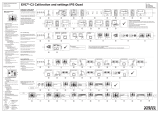
2.6Example:typicalsystem—VolvoPentaEVC
0
SeaTalk
ng
DeviceNet / SeaTalk
ng
MULTILINK
MULTILINK
DeviceNet / SeaTalk
ng
D12763-1
SeaTalk
ng
SeaTalk
ng
6
9
10
7
5
6
1
SeaTalk
ng
12 V 12 V
13
2
3 4
8
11
12
1.GPSreceiver.
2.Multifunctiondisplay.
3.Autopilotcontrollerandinstruments(e.g.helm1).
4.Autopilotcontrollerandinstruments(e.g.helm2).
5.Windtransducer.
6.iTC-5converter.
7.Speedtransducer.
8.EngineCANbus.
9.Depthtransducer.
10.EV-2.
11.PowersupplyforVolvoPentaEVCdriveinterfaceunit.
12.PowersupplyforSeaT alk
ng
backbone.
13.VolvoPentaEVCdriveinterfaceunit.
Note:Themultifunctiondisplayrequiresaseparatepower
connection.ItcannottakeitspowerfromtheSeaT alk
ng
bus.
Planningtheinstallation
17

2.7Seatalk
ng
SeaTalk
ng
(NextGeneration)isanenhancedprotocolfor
connectionofcompatiblemarineinstrumentsandequipment.It
replacestheolderSeaTalkandSeaTalk
2
protocols.
SeaTalk
ng
utilizesasinglebackbonetowhichcompatible
instrumentsconnectusingaspur.Dataandpowerarecarried
withinthebackbone.Devicesthathavealowdrawcanbe
poweredfromthenetwork,althoughhighcurrentequipmentwill
needtohaveaseparatepowerconnection.
SeaTalk
ng
isaproprietaryextensiontoNMEA2000andthe
provenCANbustechnology.CompatibleNMEA2000and
SeaTalk/SeaTalk
2
devicescanalsobeconnectedusingthe
appropriateinterfacesoradaptorcablesasrequired.
2.8NMEA2000
NMEA2000offerssignicantimprovementsoverNMEA0183,
mostnotablyinspeedandconnectivity.Upto50unitscan
simultaneouslytransmitandreceiveonasinglephysicalbusat
anyonetime,witheachnodebeingphysicallyaddressable.The
standardwasspecicallyintendedtoallowforawholenetwork
ofmarineelectronicsfromanymanufacturertocommunicateon
acommonbusviastandardizedmessagetypesandformats.
18EvolutionEV-2

Chapter3:Cablesandconnections
Chaptercontents
•3.1Generalcablingguidanceonpage20
•3.2Powerconnection—EV-2onpage20
•3.3Connectionsoverview—EV-1andEV-2onpage21
•3.4SeaTalk
ng
connection—EV-1andEV-2onpage21
•3.5DeviceNetconnection—EV-2onpage22
•3.6Driveinterfaceunitconnection—T eleexOptimusonpage22
•3.7Driveinterfaceunitconnection—VolvoPentaEVConpage23
•3.8SeaTalk
ng
cablesandaccessoriesonpage23
Cablesandconnections19

3.1Generalcablingguidance
Cabletypesandlength
Itisimportanttousecablesoftheappropriatetypeandlength
•Unlessotherwisestateduseonlystandardcablesofthe
correcttype,suppliedbyRaymarine.
•Ensurethatanynon-Raymarinecablesareofthecorrect
qualityandgauge.Forexample,longerpowercablerunsmay
requirelargerwiregaugestominimizevoltagedropalongthe
run.
Routingcables
Cablesmustberoutedcorrectly,tomaximizeperformanceand
prolongcablelife.
•DoNOTbendcablesexcessively.Whereverpossible,ensure
aminimumbenddiameterof200mm(8in)/minimumbend
radiusof100mm(4in).
100 mm (4 in)
200 mm (8 in)
•Protectallcablesfromphysicaldamageandexposuretoheat.
Usetrunkingorconduitwherepossible.DoNOTruncables
throughbilgesordoorways,orclosetomovingorhotobjects.
•Securecablesinplaceusingtie-wrapsorlacingtwine.Coil
anyextracableandtieitoutoftheway.
•Whereacablepassesthroughanexposedbulkheador
deckhead,useasuitablewatertightfeed-through.
•DoNOTruncablesneartoenginesoruorescentlights.
Alwaysroutedatacablesasfarawayaspossiblefrom:
•otherequipmentandcables,
•highcurrentcarryingacanddcpowerlines,
•antennae.
Strainrelief
Ensureadequatestrainreliefisprovided.Protectconnectors
fromstrainandensuretheywillnotpulloutunderextremesea
conditions.
Circuitisolation
Appropriatecircuitisolationisrequiredforinstallationsusing
bothACandDCcurrent:
•Alwaysuseisolatingtransformersoraseparatepower-inverter
torunPC’s,processors,displaysandothersensitiveelectronic
instrumentsordevices.
•AlwaysuseanisolatingtransformerwithWeatherFAXaudio
cables.
•Alwaysuseanisolatedpowersupplywhenusinga3rdparty
audioamplier.
•AlwaysuseanRS232/NMEAconverterwithopticalisolation
onthesignallines.
•AlwaysmakesurethatPC’sorothersensitiveelectronic
deviceshaveadedicatedpowercircuit.
Cableshielding
Ensurethatalldatacablesareproperlyshieldedthatthe
cableshieldingisintact(e.g.hasn’tbeenscrapedoffbybeing
squeezedthroughatightarea).
3.2Powerconnection—EV-2
ThepowerfortheEV-2unitisprovidedbytheSeaTalk
ng
system.
•TheEV-2unitmustbeconnectedtoaSeaTalk
ng
backbone.
ThisistypicallyachievedusingaSeaTalk
ng
5-wayconnector
blockorT-piececonnector.
•TheSeaT alk
ng
systemrequiresonlyONE12Vpowersource.
Thiscanbeprovidedbyabattery.Ifyourvesselhasa24V
supplyasuitablevoltageconvertorisrequired.
•Thepowersourcemustbeprotectedbya5Afuseoracircuit
breakerprovidingequivalentprotection.
•SeaT alk
ng
cablescarrybothdataandpowersignals.The
powerissuppliedtotheEV-2viaaSeaT alk
ng
spurcable.
•RefertotheSeaT alk
ng
referencemanualformoreinformation
ongeneralSeaT alk
ng
powerrequirements.
Powerconnection—VolvoPentaEVC
interface
TheEVCinterfaceunitrequiresa12Vpowersource,which
mustbeprovidedtotheEVCunitviaabattery.
•Ifyourvesselhasa24Vsupplyasuitablevoltageconvertor
isrequired.
•Thepowersourcemustbeprotectedbya5Afuseoracircuit
breakerprovidingequivalentprotection.
•TheEVCinterfaceunitmustbeconnectedtothe12Vpower
sourceviaaSeaTalk
ng
5-wayconnectorblock.
•ASeaTalk
ng
tobareendspowercablemustbeusedto
connecttheSeaT alk
ng
5-wayconnectorblocktothe12V
powersource.
•ThesuppliedDeviceNettoSeaT alk
ng
adaptorcablemustbe
usedtoconnecttheEVCinterfaceunittotheSeaTalk
ng
5-way
connectorblock.Thiscablecarriesbothdataandpower
signalstotheEVCunit.
20EvolutionEV-2
/