Page is loading ...

EVC
EC
-C
Electronic Vessel Control
D4, D6, D9, D12, D16
Installation
1(1)
B E


Installation
Electronic Vessel Control
EVC
EC
-C
D4, D6, D9, D12, D16
Contents
Safety precautions .............................................. 5
General information ............................................ 7
Engine monitoring and the EVC system ........... 10
Engine monitoring system ............................... 10
The EVC-C system .......................................... 11
Installation tools and literature .......................... 13
Other special equipment ..................................... 14
Major components ............................................... 15
General view .................................................... 15
Installation procedure, general .......................... 28
Cable routing ................................................... 29
Marking and color coding of cables ................. 32
Building an EVC network ................................. 33
Identification of the PCU and the HCU ............ 34
Installation procedure, engine room .................. 35
Location and mounting of the PCU and HCU .. 35
Engine–PCU cable, stern drive ....................... 36
Engine–PCU cable, Inboard engine ................ 36
Transmission cables ........................................ 37
Checking rotation of propeller, D4/D6 ............. 38
Checking rotation of propeller, D9/D12/D16 .... 39
Volvo Penta Lowspeed and Trolling ................. 42
PCU, installation ............................................. 43
Fuel and fresh water level senders ................. 43
Rudder indicator ............................................. 46
Standard bus cable PCU–HCU ...................... 45
HCU, installation .............................................. 47
Powertrim system, D4/D6 stern drive .............. 48
Gear shift actuator, D4/D6 stern drive ............. 48
© 2007 AB VOLVO PENTA
All rights to changes or modifications reserved.
Printed on environmentally-friendly paper
3

Contents cont.
Installation procedure, helm ............................... 49
Y-connector...................................................... 49
Key switch and relay ........................................ 49
Start/stop panel ............................................... 50
EVC control panel ........................................... 52
Powertrim panel............................................... 54
Relay for external accessories ........................ 55
Instruments ...................................................... 57
Instrument, panels and auxiliary cable ............ 59
Buzzer ............................................................. 60
Auxilliary dimmer unit (ADU) ........................... 61
Synchronizing cable, twin installtions .............. 62
EVC system display ......................................... 63
NMEA 0183 interface ...................................... 68
NMEA 2000 interface ...................................... 69
Multisensor ...................................................... 71
Controls, electronic .......................................... 72
Adapter for mechanical controls ...................... 75
Controls, mechanical ....................................... 76
Interface 4–20 mA ........................................... 79
EVC control panels .............................................. 82
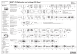
Calibration and settings ...................................... 83
General ............................................................ 83
Calibration mode ............................................. 84
Auto configuration ............................................ 84
EVC control lever combinations
Calibration summary ....................................... 86
Lever calibration .............................................. 88
Select language and units ............................... 91
Powertrim calibration ....................................... 92
Powertrim Assistance, PTA ............................. 93
Trolling calibration ............................................ 94
Slip calibration ................................................. 95
Idling speed calibration .................................... 96
OEM-mode ...................................................... 97
Fuel tank settings ............................................ 97
Fuel tank calibration ........................................ 98
Multisensor calibration ..................................... 100
EVC system display ......................................... 102
Diagnostic function ............................................. 107
Fault register ........................................................ 109
Parameter settings .............................................. 117
Starting the engine .............................................. 119
Wiring color and pin-out schematics ................ 123
Templates for controls and panels .................... 125
References to Service bulletins ......................... 136
4
Contents EVC-C

Important!
The following special warning symbols are found in
this manual and on the engine.
WARNING! Possible danger of personal injury,
damage to property or mechanical malfunction if
the instructions are not followed.
IMPORTANT! Used to draw your attention to
something that can cause damage to or malfunc-
tion of a product or damage to property.
NOTE! Used to draw your attention to important in-
formation that will facilitate the work or operation in
progress.
A summary is given below of the risks and safety pre-
cautions you must observe or carry out when install-
ing and calibrating the EVC system.
Before carrying out electric arc welding, remove:
- connector from the engine control unit
- 8-pin connector from the PCU.
Safety precautions
Introduction
This Installation Manual contains the information you
will need to install and test the Electronic Vessel Con-
trol (EVC) system.
Read this Installation Manual carefully before instal-
lation. Incorrect installation may result in personal
injury or damage to property or the engine itself.
If you do not understand or are uncertain about any
operation or information in this Installation Manual,
please contact the Volvo Penta organization.
Installation
This Installation Manual is intended for professional
use only.
The Manual must be used in conjunction with the rel-
evant Engine Operator’s Manual.
Volvo Penta will not assume any liability for damage
to materials or personal injury, which may result if the
installation instructions are not followed or if the work
is carried out by non-professional personnel.
The installer is responsible for ensuring that the
system operates in accordance with this Installation
Manual.
Work procedures
These instructions are for use by suitably qualified
personnel, referred to as the installer in these instruc-
tions.
Refer to the specific Engine Operator’s manual for
relevant information where necessary, especially re-
garding safety and engine operation.
The work must be done at Volvo Penta’s service
workshops, boat builders or other authorised and
suitably equipped workshops with personnel who
have the appropriate qualifications and experience.
D4 and D6 engines
Press the lock tab down and pull the connector out.
Refit the connector to the engine control unit after
disconnecting the welding equipment.
5

D9, D12 and D16 engines
Press the lock tab up and pull the connector/connec-
tors out. Refit the connector to the engine control unit
after disconnecting the welding equipment.
Take care to avoid all moving parts of the engine
during testing and operation. Approaching an
engine which is operating is a hazard to personal
safety. Loose clothing or long hair can become
entangled in moving parts, and may cause seri-
ous personal injury.
Never carry out work on an engine that is sus-
pended from a hoist.
The engine must not be run in areas where there
are explosive materials or gases.
Only start the engine in a well-ventilated area.
If operating the engine in a closed area ensure
that there is exhaust ventilation leading out of the
work area to remove exhaust gases and crank-
case ventilation emissions.
Never allow an open flame or electric sparks
near the batteries. Never smoke close to the bat-
teries. The batteries give off hydrogen gas during
charging, which can form an explosive mixture
when mixed with air. This gas is easily ignited
and highly flammable. Incorrect connection of
the battery can cause a single spark, which is
sufficient to cause a gas explosion. Do not alter
the battery connections when attempting to start
the engine (spark risk) and do not lean over any
of the batteries. Refer to the instructions in the
Engine Instruction Manual.
Always ensure that the + (positive) and – (nega-
tive) battery leads are correctly installed on their
corresponding terminal posts on the batteries. In-
correct installation can result in serious damage
to the electrical equipment. Refer to the wiring
diagrams in the Engine Instruction Manual.
Always use protective goggles when charging
or handling the engine batteries. The battery
electrolyte fluid contains sulfuric acid which is
highly corrosive. If the battery electrolyte comes
into contact with unprotected skin, wash it off im-
mediately using copious amounts of clean water
and soap, then seek medical assistance. If the
electrolyte fluid comes into contact with the eyes,
flush your eyes immediately (preferable using an
eye bath) with copious amounts of clean water,
and obtain medical assistance without delay.
IMPORTANT! AB Volvo Penta has developed
and tested the complete EVC system and its
components. However, non Volvo Penta compo-
nents or components installed in a way that differ
from the instructions may cause the system to
malfunction. In this case Volvo Penta do not ac-
cept any responsability.
6
Safety precautions EVC-C

General information
About the Installation Manual
This publication is intended as a guide for the instal-
lation of Volvo Penta EVC system for D4, D6, D9,
D12 and D16 engines, Aquamatic and inboard use.
The publication is not comprehensive and does not
cover every possible installation, but is to be regard-
ed as recommendations and guidelines applying to
Volvo Penta standards. Detailed Installation Instruc-
tions are included in most of the accessory kits.
These recommendations are the result of many years
of practical experience of installations from all over
the world. Departures from recommended proce-
dures etc. can be necessary or desirable, however, in
which case the Volvo Penta organization will be glad
to offer assistance in finding a solution for your par-
ticular installation.
It is the sole responsibility of the installer to ensure
that the installation work is carried out in a satisfac-
tory manner, it is operationally in good order, the ap-
proved materials and accessories are used and the
installation meets all applicable rules and regulations.
This Installation Manual has been published for
professionals and qualified personnel. It is therefore
assumed that persons using this book have basic
knowledge of marine propulsion systems and are
able to carry out related mechanical and electrical
work.
Installation of electrical systems shall only be carried
out by a professional boat electrician.
Only components, cables, connections etc, delivered
or approved by the manufacturer may be used. The
manufacturer will accept no responsibility what so
ever if this requirement is ignored.
Volvo Penta continuously upgrades its products and
reserves the right to make changes. All the informa-
tion contained in this manual is based on product
data available at the time of print. Notification of
any important modifications to the product causing
changes to installation methods after this date will be
made in Service Bulletins.
NOTE! Commercial and classified systems including:
- MCC system
- CU 305 system
- SDU (Shut Down Unit)
Please refer to Installation Marine Propulsion, Die-
sel Engines D5–D16.
Plan installations with care
Great care must be taken in the installation of en-
gines and their components if they are to operate
perfectly. Always make sure that the correct specifica-
tions, drawings and any other data are available be-
fore starting work. This will allow for correct planning
and installation right from the start.
Plan the engine room so that it is easy to carry out
routine service operations involving the replacement
of components. Compare the engine Service Manual
with the original drawings showing the dimensions.
It is very important when installing engines that no
dirt or other foreign matter gets into the fuel, cooling,
intake or turbocharger systems, as this can lead to
faults or engine seizure. For this reason the systems
must be sealed. Clean supply lines and hoses before
connecting them to the engine. Only remove protec-
tive engine plugs when making a connection to an
external system.
Important
Never cut or modifiy the Volvo Penta EVC cable har-
nesses. For extra power supply use the Volvo Penta
relay for accessories.
Refer to the Relay for external accessories section.
Never use any kind of grease in the EVC connectors.
7

Certified engines
The manufacturer of engines certified for national
and local environmental legislation (Lake Constance
for example) pledges that this legislation is met by
both new and currently operational engines. The
product must compare with the example approved
for certification purposes. So that Volvo Penta, as a
manufacturer, can pledge that currently operational
engines meet environmental regulations, the follow-
ing must be observed during installation:
• Servicing of ignition, timing and fuel injection
systems (gasoline) or injector pumps, pump set-
tings and injectors (diesel) must always be car-
ried out by an authorised Volvo Penta workshop.
• The engine must not be modified in any way ex-
cept with accessories and service kits developed
for it by Volvo Penta.
• Installation of exhaust pipes and air intake ducts
for the engine compartment (ventilation ducts)
must be carefully planned as its design may af-
fect exhaust emissions.
• Seals may only be broken by authorised person-
nel.
IMPORTANT! Use only Volvo Penta Genuine
Parts.
Using non-genuine parts will mean that AB
Volvo Penta will no longer take responsibility
for the engine meeting the certified design.
All damage and costs caused by the use of non-
genuine replacement parts will not be covered
by Volvo Penta.
Seaworthiness
It is the boat builder’s duty to check that the security
requirements apply to the market in which the boat
is sold. In the USA for example, these are the US
Federal Regulations for pleasure boats described
in Title 46. The requirements described below apply
to the EU principles. For information and detailed
descriptions of the safety requirements that apply to
other markets, contact the authority for the country
concerned.
As of June 16 1998, pleasure boats and certain as-
sociated equipment marketed and used within the
EU must bear CE labels to confirm that they meet
the safety requirements stipulated by the European
Parliament and Council of Europe’s directive for plea-
sure boats. The normative requirements can be found
in the standards drawn up to support the directive’s
objective of uniform safety requirements for pleasure
boats in EU countries.
Certificates that grant the right for CE label use and
confirm that boats and equipment meet safety re-
quirements are issued by approved notified bodies.
In many Member States the classification societies
have become the notified bodies for pleasure boats,
e.g. Lloyd’s Register, Bureau Veritas, Registro Italiano
Navale, Germanischer Lloyd, etc.
In many cases completely new institutions have been
approved as notified bodies. The directive also allows
boat builders and component manufacturers to issue
assurances of compliance with the requirements of
the directive. This requires the manufacturer to store
the prescribed product documentation in a place that
is accessible to the monitoring authority for at least
ten years after the last product is produced.
Life boats and boats for commercial activities are ap-
proved by classification societies or by the navigation
authority for the boat’s registered country.
Joint liability
Each engine consists of many components working
together. One component deviating from its technical
specification can cause a dramatic increase in the
environmental impact of an engine. It is therefore vital
that systems that can be adjusted are adjusted prop-
erly and that Volvo Penta Genuine Parts are used.
Certain systems e.g.components in the fuel system
may require special expertise and special test equip-
ment. Some components are sealed at the factory for
environmental reasons. No work should be carried
out on sealed components except by authorised per-
sonnel.
Remember that most chemical products damage the
environment if used incorrectly. Volvo Penta recom-
mends the use of biodegradable degreasing agents
for cleaning engine components, unless otherwise
indicated in a Workshop Manual. Take special care
when working on board boats to ensure that oil and
waste are taken for destruction and not accidentally
pumped into the environment with bilgewater.
8
General information EVC-C

Conversion factors
Metric to U.S. or IMP. conversion factors: U.S. or IMP. to metric conversion factors:
To convert To convert
from To Multiply by from To Multiply by
Length mm inch 0.03937 inch mm 25.40
cm inch 0.3937 inch cm 2.540
m foot 3.2808 foot m 0.3048
Area mm² sq.in. 0.00155 sq. in. mm² 645.2
m² sq. ft. 10.76 sq. ft. m² 0.093
Volume cm³ cu. in. 0.06102 cu. in. cm³ 16.388
litre, dm³ cu. ft. 0.03531 cu. ft. litre, dm³ 28.320
litre, dm³ cu. in. 61.023 cu. in. litre, dm³ 0.01639
litre, dm³ imp. gallon 0.220 imp. gallon litre, dm³ 4.545
litre, dm³ U.S. gallon 0.2642 U.S. gallon litre, dm³ 3.785
m³ cu. ft. 35.315 cu.ft. m³ 0.0283
Force N lbf 0.2248 lbf N 4.448
Weight kg lb. 2.205 lb. kg 0.454
Power kW hp (metric)
1)
1.36 hp (metric)
1)
kW 0.735
kW bhp 1.341 bhp kW 0.7457
kW BTU/min 56.87 BTU/min kW 0.0176
Torque Nm lbf ft 0.738 lbf ft Nm 1.356
Pressure Bar psi 14.5038 psi Bar 0.06895
MPa psi 145.038 psi MPa 0.006895
Pa mm Wc 0.102 mm Wc Pa 9.807
Pa in Wc 0.004 in Wc Pa 249.098
kPa in Wc 4.0 in Wc kPa 0.24908
mWg in Wc 39.37 in Wc mWg 0.0254
Energy kJ/kWh BTU/hph 0.697 BTU/hph kJ/kWh 1.435
Work kJ/kg BTU/lb 0.430 BTU/lb kJ/kg 2.326
MJ/kg BTU/lb 430 BTU/lb MJ/kg 0.00233
kJ/kg kcal/kg 0.239 kcal/kg kJ/kg 4.184
Fuel g/kWh g/hph 0.736 g/hph g/kWh 1.36
consump. g/kWh lb/hph 0.00162 lb/hph g/kWh 616.78
Inertia kgm² lbft² 23.734 lbft² kgm² 0.042
Flow, gas m³/h cu.ft./min. 0.5886 cu.ft./min. m³/h 1.699
Flow, liquid m³/h US gal/min 4.403 US gal/min m³/h 0.2271
Speed m/s ft./s 3.281 ft./s m/s 0.3048
mph knots 0.869 knots mph 1.1508
Temp. °F=9/5 x °C+32 °C=5/9 x (°F–32)
1) All hp figures stated in the catalogue are metric.
9
EVC-C General information

Engine monitoring system
The engines are equipped with common rail system
and electronically controlled injectors (D4, D6) or unit
injectors (D9, D12, D16) with an electronic control
Engine monitoring and the EVC system
unit.
The injectors contain an electro-magnetic valve which
sets the amount of fuel injected and the correct tim-
ing. The monitoring system measures the charge air
pressure and temperature, and calculates the avail-
able air mass. This determines the maximum amount
of fuel that can be injected (smoke limiter function).
The system also limits the maximum torque available
at the engine speed registered to protect the engine
and transmission from overload.
To protect the engine at too high coolant or charge air
temperatures and boost pressure as well as oil pres-
sure, the monitoring system reduces the amount of
fuel (reduced engine output) until the current values
are normalized.
The engine monitoring system also has a diagnostic
system, which helps users and service technicians to
determine the cause of any malfunctions in the sys-
tem quickly by using the diagnostic tool.
Any fault is shown on the EVC system tachometer
display / EVC system display and the VODIA diag-
nostic scan tool. The diagnostic tool has menus in
several languages.
Diagnostics
Engine speed
Throttle
Oil pressure
Oil temp.
Cooling temp.
Charge air press.
Charge air temp.
Fuel temp.
Water in fuel
Camshaft pos.
Ignition
timing
Fuel
quantity
Engine
Control
Unit
HCU
(Helm station
Control Unit)
PCU
(Powertrain
Control Unit)
ECU
(Engine
Control Unit)
HCU
(Helm station
Control Unit)
CAN bus
Actuator
(gear shifting
DPH/DPR)
10

The EVC
EC
-C system
The Electronic Vessel Control (EVC) system is a so
called distributed system. The principle of a distrib-
uted system is to have "small" electronic units, called
nodes, located at suitable places in the boat.
The EVC nodes are the Powertrain Control Unit
(PCU) and the Helm station Control Unit (HCU).
Nodes are located close to the components they are
connected to. A helm node is located close to the
helm. A powertrain node is mounted in the engine
room.
Each node is connected to a number of adjacent
components, such as sensors, controls, instruments
and actuators.
Each PCU and HCU is programmed for a specific
engine. There is a sticker with serial no. and chassis
no. on each PCU and HCU. The serial no. must cor-
respond with the sticker on the engine.
A data bus, a CAN bus, connects the nodes to each
other. Together they form a network and exchange
information and take advantage of each others’ ser-
vices. The principle of forming a network of nodes to
which all components are connected reduces wiring
radically. A CAN bus can be very long, but in the EVC
system the bus length shall not exceed 40 meters.
CAN stands for Controller Area Network, an industry
standard for communication between nodes in distrib-
uted systems.
A distributed system supports a growing multiplicity
of system configurations and optional features. New
nodes can be connected to the network with minimal
wiring redesign. New effective functionality can be
created by letting the nodes interact and combine
their capabilities, creating a more useful and safe
product.
Functionality
Engine speed and gear shift
Speed and gear shift contol is handled electronically.
The reverse gear or stern drive has high speed shift-
ing protection. Dual function electronic controls can
be used in the EVC system as well as can mechani-
cal controls with control adapters.
Multiple helm stations
Up to four helm stations can easily be installed (plug
in). The EVC system provides different options for
station transfers in neutral position or under way. An-
other safety feature is a helm station "lock function"
to avoid unexepted station transfers.
Engine synchronization
Engine synchronization results in better comfort,
good fuel economy and minimized wear due to less
vibration and reduced noise level. The master (port)
and slave (starboard) systems must be able to com-
municate to allow synchronization. For this reason a
synchronization cable must be installed at each helm.
Instrumentation
The instruments use a serial communication bus. The
serial communication bus in combination with EVC
radically reduces wiring and simplifies installation.
Gauges are available with white or black dial face
and chromed or black bezel.
EVC system tachometer
This tachometer will be recommended as a standard
for all installations. All alarms are available in the ta-
chometer. The tachometer has a built in buzzer alarm
and an output to the instrument serial bus (easy-link).
Powertrim
The function is considerably improved compared
with non EVC governed Powertrim systems. EVC
introduces a new trim panel with the same design as
other EVC control panels. If you have a twin engine
installation the stern drives can be both individually
and simultaneously controlled.
Trimming in and out can be calibrated to suit the spe-
cific installation. To protect the drive it cannot be tilted
when engine is running above a certain rpm.
Powertrim Assistant (PTA)
The EVC system controls automatically the drive
trim position proportional to the engine speed. Trim
positioning is set in five steps/levels. Settings can
be done by the LCD tachometer or the EVC display
and the EVC control panel. This feature is software
related and only supported by the EVC-C system.
Hardware changes are not needed. Old versions of
the EVC system cannot be upgraded to PTA level.
EVC system display
The EVC system display is a complement or replace-
ment for the EVC system tachometer and optional in-
struments. The display shows operation information,
information messages and alarms. The user selects
what operation information to display with the buttons
on the display. The EVC system display can display
more than one operation information at one and the
same time. The display also has access to the same
display mode and calibration functions as for the EVC
system tachometer display.
11
EVC-C Engine monitoring and the EVC system

Fuel level
EVC-C makes it easy to install the fuel level indica-
tion. All you need is a fuel level sensor in the fuel tank
and a fuel level gauge or a display at the helm. If a
fuel level gauge is used it must be connected to the
instrument serial communication bus. The PCU–en-
gine cable harness has an input for the fuel level
sender.
The system has a "Multipoint setting" facility with a
possibility of setting fuel level in six steps depending
on the fuel tank shape.
Trip computer
EVC supports trip computer functions if following are
installed.
- multisensor or NMEA 0183/NMEA 2000 compat-
ible component (plotter, GPS, paddle wheel etc)
- fuel level sender
- software for trip computer. Order and download
from VODIA website.
Trip computer information can be displayed on the
EVC system tachometer or/and on the optional EVC
system display.
Trip data: Fuel rate, fuel consumption, fuel consump-
tion/time, trip fuel consumtion, trip fuel consumption/
time, remaining fuel, trip hours, trip distance, remain-
ing distance to empty tank, remaining time until tank
is empty.
NOTE! If no trip computer software is installed, only
fuel volume will be presented in the EVC system ta-
chometer.
EVC system display: Fuel rate will be shown in the
"Engine data window".
Fresh water level
EVC makes it easy to install the water level indica-
tion. All you need is a level sensor, 3–180 ohm, in the
water tank and a level gauge at the helm. If a water
level gauge is used it must be connected to the in-
strument serial communication bus. The PCU–engine
cable harness has an input for the fresh water level
sender.
Rudder indicator
To install a rudder indicator you need a sensor,
3–180 ohm, at the rudder and a gauge or a display at
the helm. The gauge shall be connected to the instru-
ment serial communication bus. The PCU–engine
cable harness has an input for the rudder sender.
Volvo Penta Lowspeed function D4, D6, D9, D12
Boats with powerful engines can be difficult to ma-
neuver in narrow waters since the boat speed is high
even at idling speed. This problem is minimised us-
ing Volvo Penta Lowspeed functionality. EVC system
controls the reverse gear to slip hydraulically so that
lower boat speed can be achieved.
The gear slip can be implemented by means of a
separate trolling valve or by controlling primary or
secondary solenoids, depending on type of reverse
gear. The reverse gear also has to be equipped with
an rpm sensor and a tooth wheel on the output shaft
as well as an oil pressure/oil temperature sensor.
Volvo Penta trolling function, D9, D12
The EVC system controls the reverse gear to slip hy-
draulically so that lower boat speed can be achieved
with maintained engine rpm. The gear slip is imple-
mented by means of a separate trolling valve. The
reverse gear also has to be equipped with an rpm
sensor and a tooth wheel on the output shaft as well
as an oil pressure/oil temperature sensor. Default
trolling slip is 70%. Max slip is 80% but suitable slip is
dependent on each installation. Slip can be set from
10% up to 80% by using the VODIA tool.
NMEA support
The EVC system supports NMEA 0183 or NMEA
2000 by means of hardware interfaces.
Boat speed, echo sounder and water temp
(Multisensor)
The multisensor is connected to the multilink cable.
Data from the multisensor are shown in the tachom-
eter or the EVC system display and the speedometer
instrument.
4–20 mA interfaces
The EVC system supports different control systems
from the aftermarket that support 4–20 mA by means
of input or output interfaces. No calibration is needed.
12
Engine monitoring and the EVC system EVC-C

Installation tools and literature
Posters
Installation procedure Electronic Vessel Control
EVC-C D4, D6
Installation procedure Electronic Vessel Control
EVC-C D9, D12, D16
Templates for panels and controls
All installation instructions and templates are in-
cluded in each kit. Please refer to the Templates for
controls and panels chapter
Installation manuals
For D4, D6 with IPS: Installation EVC
EC
-C Electron-
ic Vessel Control Volvo Penta IPS.
For D4, D6: Installation Aquamatic DPH, DPR,
Volvo Penta IPS, Inboard - D4, D6.
For D9, D12 and D16: Installation Marine Propul-
sion Diesel Engines Inboard - D5–D16 series.
Multimeter
Special tool 9812519
Installation instructions
Installation instructions are included in most kits
VODIA Diagnostic scan tool
The VODIA tool is used in diagnostic work to read
fault codes in clear text. It can also be used to log
EVC parameters.
It is very useful in fault tracing since it makes it possi-
ble to see the values the EVC nodes read and send.
Please contact the Volvo Penta organization for or-
dering.
13

Other special equipment
The tools below are intended for use in work on the cable harnesses of the engine. The tools are not included in
Volvo Penta’s range, they must be ordered from a local AMP or Deutsch dealer. If you experience problems in
contacting a dealer, please contact Volvo Penta Quality Action Center for advice.
Deutsch connectors
HDT-48-00 Crimping tool
0411-310-1605 Disassembly tool
16-pin CPC connector, d=1.6 mm (0.063")
725 840-1 Disassembly tool
58 495-1 Crimping tool
JPT connector (42-pin EDC, 2 and 3-pin
Bosch etc.)
726 534-1 Disassembly tool 1.6 mm (0.063")
pin width
726 519-1 Disassembly tool 2.8 mm (0.11")
pin width
825 514-1 Crimping tool
Blades and sockets 3.5 mm (0.14")
725 9380 Disassembly tool
825 582-2 Crimping tool
4.8 mm (0.19") and 6.3 mm (0.25") cable clamps.
Tongues and socket terminals
825 514-1 Crimping tool
Deutsch service kit incl. connectors and crimping
tool
11 666 200 NOTE! Volvo Part no. only
AMP 726 519
AMP 825 514 AMP 825 582AMP 725 938
AMP 725 840
AMP 726 534AMP 58 495HDT-48-00
14

Major components
General view
EVC system with two inboard engines (twin installa-
tion) and three individual helm stations.
Helm Control
Unit (HCU),
flybridge. Star-
board engine
Helm Control
Unit (HCU),
flybridge.
Port engine
(master)
Helm Control
Unit (HCU),
main station.
Port engine
(master) Helm Control
Unit (HCU),
main station.
Starboard
engine
Powertrain
Control
Unit (PCU).
Port engine
(master)
Helm Control
Unit (HCU).
Starboard
engine
Helm Control Unit
(HCU). Port engine
(master)
Engine
Control
Module
(ECM)
Electronic
Controls
Powertrain Control
Unit (PCU).
Starboard engine
Reverse
gear sole-
noid valves
15

Electronic controls
Top mounted controls
Control, single engine
Control, twin installation
Side mounted control
Side mounted lever control for electronic control of
engine speed and gear shifting. Available for single
installation.
Side mounted control
with Powertrim switch
Side mounted lever control for electronic control of
engine speed, gear shifting and Powertrim. Available
for single installation. Including cable 2.0 m (6 ft).
Lever controls for electronic control of engine speed
and gear shifting. Available in black or stainless steel
housing and for both single and twin installation.
The controls are equipped with neutral switches.
Side mounted control.
DPH and DPR applications
Neutral switch
Potentiometer
Neutral switch
Potentiometer
Side mounted lever control for electronic control of
engine speed, gear shifting. The control is available
with buttons for Powertrim adjustments and control.
Available for single installation. Including cable 2.0 m
(6 ft).
16
Major components EVC-C

EVC control panels
Control panel,
single engine
Control panel,
twin installation
A control panel is required to start and operate EVC
engines.
The panels can be installed with frames or flush on
dashboard. The panels are supplied with the neces-
sary connections.
Powertrim control panel,
stern drive DPH/DPR
The panel can be installed with a frame or flush on
dashboard. The panel is supplied with the necessary
connections.
17
EVC-C Major components

Start/stop panel,
single engine
Start/stop panel,
twin installation
Start/stop control panel,
secondary helm station
To start and stop the engine from a secondary helm
station.
The panel can be mounted with a frame or flush on
dashboard. The panels are supplied with all neces-
sary connections.
EVC system display,
including cable
The Volvo Penta EVC system display is an on-board
instrument for indication of engine operating values,
boat speed and other data. The display consists of
a self-contained, computerised unit for fixed installa-
tion on a dash board. A Liquid Crystal Display (LCD)
screen is used for data presentation.
The EVC system display can show information from
one or two engines.
If only a display is used (no tachometer) this requires
an additional buzzer and an instrument, panels and
auxiliary cable.
IMPORTANT! An EVC system display can be
connected together with a tachometer. The dis-
play can also substitute a tachometer. The EVC
system must have either a tachometer or a dis-
play.
Key switch, main station
On the main helm station a key switch to power up
the system and start/stop the engine must be in-
stalled.
The key switch is available in kits for single and
twin installations. A kit for twin installations has two
switches which can be operated with the same key.
18
Major components EVC-C

Instruments
There is a variety of instruments available for the
EVC system. The instruments can be ordered with
black or white dial face.
The instruments can be mounted with an attaching
ring or clamp or flush on dashboard. The instruments
are delivered with the necessary wiring for connec-
tion to the system.
Some of the most common instrument types are
shown below.
Voltage
∅ 52 mm (2.05")
(12V/24V)
Alarm panel (option)
∅ 52 mm (2.05")
Engine oil pressure
∅ 52 mm (2.05")
(bar alt. psi)
Coolant temperature
∅ 52 mm (2.05")
(°C alt. °F)
Trim instrument, analog
∅ 52 mm (2.05")
Trim instrument, digital
∅ 52 mm (2.05")
Rudder indicator
∅ 52 mm (2.05")
Fuel level
∅ 52 mm (2.05")
EVC system
tachometer. Engine
speed incl. buzzer
and communication
display
∅ 85 mm (3.35")
∅ 110 mm (4.33")
(rpm).
The EVC system tachometer has an integrated
buzzer and a communication LCD showing alarms,
diagnosis data and information about the system.
NOTE! The EVC system allows maximum one
tachometer per helm station (HCU).
Speedometer
∅ 85 mm (3.35")
∅ 110 mm (4.33")
(knots, mph)
19
EVC-C Major components

Instrument ring kit,
chrome/black
The kit contains a front ring, a gasket and an attach-
ing nut or an attaching clamp.
Diameters 52 mm (2.05"), 85 mm (3.35") or 110 mm
(4.33") depending on type of instrument.
Gasket for flush mounted
instruments
If the instruments should be flush mounted into the
instrument panel, a gasket must be fitted to prevent
water from entering behind the panel.
Auxiliary dimmer unit (ADU)
Front ring
Attaching nut
Attaching clamp
Gasket
Transom mounted
sensor
Hull mounted
sensor
Multisensor
The multisensor is available in two designs, for tran-
som mounting and for hull mounting. The multisen-
sor submits data about boat speed, water depth and
water temperature. Data can be shown in the EVC
display. The speed data is also available in an instru-
ment (speedometer).
4–20 mA input interface for
auxiliary control levers
Input interface to aftermarket control systems that
support 4–20 mA. No calibration is needed.
Dimmer for instrument lights in auxilliary instruments
and equipment. Instruments not supported by the
EVC system (third party instruments). The function is
controlled by the multifunction button ( ) on the EVC
control panel.
4–20 mA output interface for
auxiliary control levers
Output interface to aftermarket control systems that aftermarket control systems thataftermarket control systems that
support 4–20 mA. No calibration is needed.
20
Major components EVC-C
/