Extron FOXBOX T HD-SDI User manual

Category
Network media converters
Type
User manual
1
IMPORTANT:
Go to www.extron.com for the complete
user guide, installation instructions, and
specifications bef
ore connecting the
pr
oduct to the po
wer source.
FOXBOX T HD-SDI • Setup Guide
This guide provides instructions for an experienced installer to install the Extron FOXBOX T HD-SDI
transmitter and to make all connections.
The FOXBOX T HD-SDI transmits 3G HD-SDI, HD-SDI, and SDI video and embedded digital audio
via a single ber optic cable. A compatible Extron ber optic receiver receives the image and outputs the video and audio. The transmitter
is compatible with existing Extron FOX, FOXBOX, and PowerCage FOX VGA, DVI, HDMI and SR HDMI receivers and all FOX II receivers.
The transmitter can also send optional analog audio and RS-232 control signals. With a second ber optic cable, the transmitter can
receive RS-232 responses from the connected receiver.
NOTE: There are operational limitations when connected to an Extron FOX II receiver. The serial return from the receiver does not work.
Neither digital nor analog audio is available at the receiver; analog return audio continues to be available at the transmitter.
WARNING: The FOXBOX T HD-SDI outputs continuous invisible light (Class 1 rated), which may be harmful to the eyes; use with
caution. Plug the attached dust caps into the optical transceivers when the ber cable is unplugged.
AVERTISSEMENT : Le FOXBOX T HD-SDI émet une lumière invisible en continu (conforme à la classe1) qui peut être dangereux
pour les yeux, à utiliser avec précaution. Branchez les protections contre la poussière dans l’ensemble émetteur/récepteur lorsque
le câble bre optique est débranché.
Installation
For additional mounting details and considerations, see the FOXBOX T HD-SDI User Guide at www.extron.com.
Step 1 — Mounting
Turn off or disconnect all equipment power sources and mount the transmitter and a compatible receiver as required.
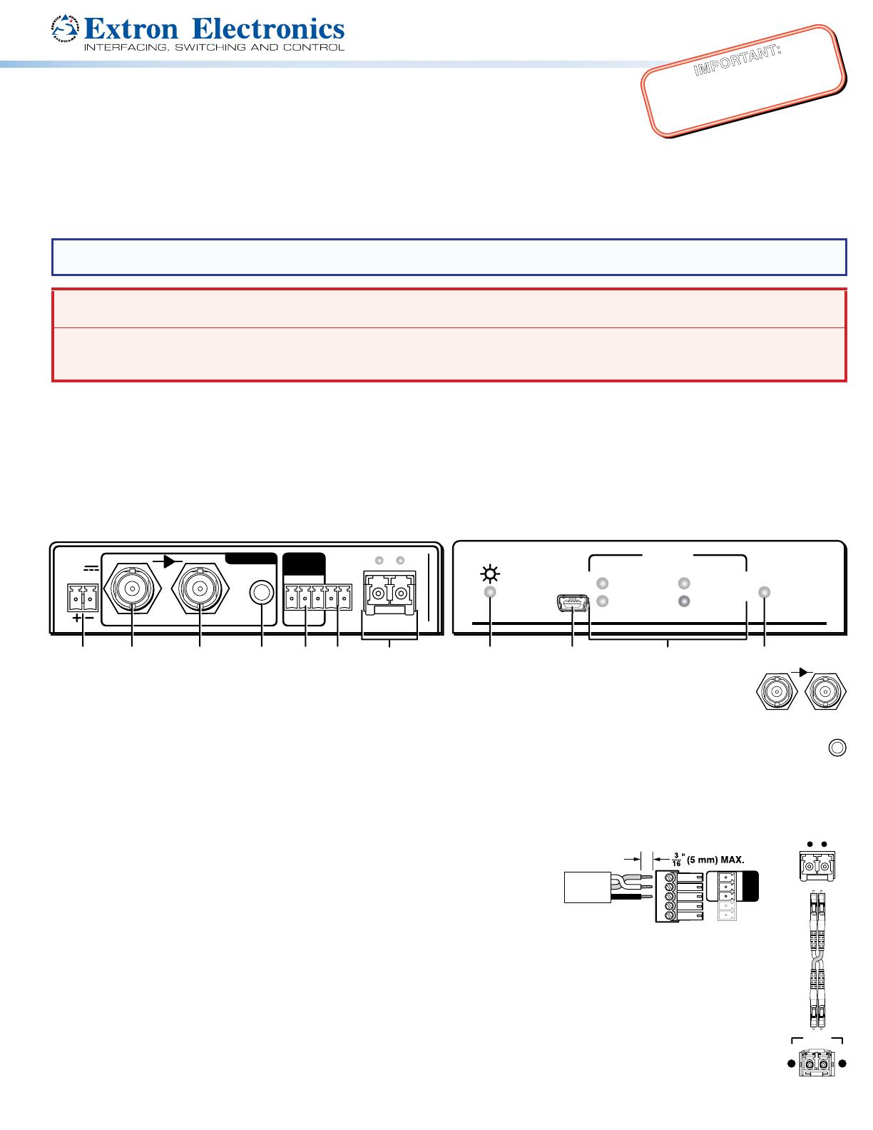
Step 2 — Connections and Indications
F
O
XB
O
X T HD-
S
DI
P
O
WE
R
3G/
HD
/S
D
I
L
OO
P THR
U
AU
DI
O
O
PTI
C
A
L
RS
-23
2
ALAR
M
Tx R
G
1
2
R
x
Tx
INP
U
T
S
US
O
VE
R
FIBER
1
2V
0
.
5A
MAX
FOXBOX T HD-SDI
POWER
3G/HD/SDI LOOP THRU
AUDIO
OPTICAL
RS-232
ALARM
Tx Rx G12
RxTx
INPUTS OVER
FIBER
12V
0.5A MAX
FO
XB
O
X T HD-
S
D
I
RATE
2.97
G
bp
s
E
xtron
CO
NFI
G
1
.485
G
b
ps
2
7
0
Mb
p
s
U
n
k
nown
A
UDI
O
FOXBOX T HD-SDI
RATE
2.97 Gbps
Extron
CONFIG
1.485 Gbps
270 Mbps
Unknown
AUDIO
Front PanelRear Panel
II JJ KK
CCBBAAGG FFDD EE
HH
A
3G/HD/SDI input port — Connect an HD-SDI, SDI, or 3G-SDI video input to this BNC connector. The transmitter
3G/HD/SDI LOOP THRU
also accepts embedded digital audio on this port.
B
Loop-Thru portConnect a local digital display to this BNC connector for a buffered loop-through of the input
signal.
C
Audio input connector — If desired, plug an analog audio input into the transmitter via this stereo mini jack connector.
A
UDI
O
This input can be selected in place of the audio embedded in the 3G/HD/SDI input for the Loop-Thru output using the Simple
Instruction Set (SIS™) command E
I
n
AFMT
} SIS command, where n =:
0 = auto1 = 2-channel digital2 = analog
The switcher responds with AfmtIn]. See the FOXBOX T HD-SDI User Guide at www.extron.com, for details.
D
Over Fiber RS-232 port — Connect a control device to the three leftmost poles
of this 3.5 mm, 5-pole captive screw connector for RS-232 communication with a
device on the receiver end.
E
Optical port and LEDs —
Ò
Tx (required) — For all one-way video, audio, and serial communications
from the transmitter to the receiver, connect a ber optic cable to the Tx LC
connector.
Connect the opposite end of this ber optic cable to the Rx connector on a compatible receiver.
Ù
Rx (optional) — Connect a ber optic cable for all one-way return serial communications from the receiver to
the transmitter.
Connect the opposite end of this ber optic cable to the Tx connector on a compatible receiver in normal
conguration (see the User Guide for the connected receiver).
Tx Link and Rx Link LEDs — When lit, the link is active (light is received).
Tr
ansmitter
to
Receiver
OPTICAL
Rx
Tx
LINK
LINK
Ò
ÒÙÙ
OPTICAL
RxTx
RS-232
Device
RS-232
ALARM
Tx Rx G
12
OVER
FIBER
Rx
Tx
Gnd
2
68-2436-50 Rev. A
01 15
Extron Headquarters
+800.633.9876 Inside USA/Canada Only
Extron USA - West Extron USA - East
+1.714.491.1500 +1.919.850.1000
+1.714.491.1517 FAX +1.919.850.1001 FAX
Extron Europe
+800.3987.6673
Inside Europe Only
+31.33.453.4040
+31.33.453.4050 FAX
Extron Asia
+65.6383.4400
+65.6383.4664 FAX
Extron Japan
+81.3.3511.7655
+81.3.3511.7656 FAX
Extron China
+86.21.3760.1568
+86.21.3760.1566 FAX
Extron Middle East
+971.4.299.1800
+971.4.299.1880 FAX
Extron Korea
+82.2.3444.1571
+82.2.3444.1575 FAX
Extron India
1800.3070.3777
(Inside India Only)
+91.80.3055.3777
+91.80.3055.3737 FAX
© 2015 Extron Electronics All rights reserved. All trademarks mentioned are the property of their respective owners. www.extron.com
FOXBOX T HD-SDI • Setup Guide (Continued)
F
Alarm port — For remote monitoring of the received ber optic link (Rx), connect a locally-constructed or furnished
RS-232
ALAR
M
Tx Rx G
12
OVER
FIBER
monitoring device to the transmitter via the two rightmost poles (1 and 2) of this 5-pole captive screw connector. When the
transmitter does not detect a light link on ber cable Rx (optional), pin 1 and pin 2 of this port are shorted together.
G
Power — Connect the included 12 VDC power supply to the transmitter, as
Power Supply
Output Cord
Captive Screw
Connector
SECTION A–A
Ridges
Smooth
AA
Tie
Wrap
3
5
shown at right. Use the included tie-wrap to strap the cord to the captive screw
connector.
Connect an IEC power cord between the power supply and a 100-240 VAC,
50-60 Hz source.
H
Configuration port — Plug a computer or other device into the transmitter via
this USB mini-B port for remote control of the transmitter. See the “Programming
Guide” section of the FOXBOX T HD-SDI User Guide at www.extron.com, for a
detailed listing of SIS commands.
I
Power ( ) indicator — Indicates that the transmitter is receiving power.
J
Rate indicators — Indicate the input video rate detected on the 3G/HD/SDI input BNC.
RATE
2.97 Gbps
CONFIG
1.485 Gbps
270 Mbps
Unknown
AUDIO
The recognized rates are 2.97 Gbps, 1.485 Gbps, and 270 Mbps. The Unknown LED
indicates that an input is detected, but that the transmitter does not recognize the rate.
K
Audio indicator — Indicates that the transmitter is detecting a digital or analog audio
input.
Operation
After all devices are connected and powered on, the system is fully operational. If any issues arise, verify that the cables are routed
and connected properly.
Application Diagram
FOXBOX T HD-SDI
POWER
3G/HD/SDI LOOP THRU
AUDIO
OPTICAL
RS-232
ALARM
Tx Rx G12
RxTx
INPUTSOVER
FIBER
12V
0.5A MAX
POWER
12V
--A MAX
G
Tx Rx RTSCTS
COM 1
G
Tx Rx
COM 2
VCG
VOL
RELAYS
1 2 C
1 2 3 4 G
DIGITAL I/O
PWR OUT = 6W
eBUS
+V +S
-S
G
LAN
IPCP PRO 250
IR/S
S G
FOXBOX SR HDMI
LINK
LINK
OPTICAL
RxTx
HDMI
AUDIO
OUTPUTS
REMOTE
RS-232
Tx Rx
RS-232
OVER FIBER
ALARM
Tx Rx 1 2
POWER
12V
1.0 A MAX
LR
OFF
ON
HDMI AUDIO
POWER STANDBY
MODEL 80
FLAT PANEL
Help
System
Off
Display
Room
Control
Off
Mute
Screen
Lighting
December 15, 2013 - 7:58 AM
Audio
Control
Volume
Mute
Tuner
1 2 3
VCRLaptop PC DVD
Doc
Cam
Tuner
On
Channel
Last
Presets
More
Presets
321
654
987
Enter
0
RS-232
Ethernet
Ethernet
PTZ Camera
Display
RS-232
Ext
ron
FO
XBOX T HD-SDI
Fi
ber Optic Transmitter
3G-SDI
HDMI
Extron
FOXBOX SR HDMI
Fiber Optic Receiver
TCP/IP
Network
Extron
TLP Pro 1020T
10" Tabletop
TouchLink
Pro Touchpanel
Extron
IPCP Pro 250
IP Link Pro
Control
Processor
Up to 30 km (18.75 miles) singlemode ber SM Model
  • Page 1 1
  • Page 2 2

Extron FOXBOX T HD-SDI User manual

Category
Network media converters
Type
User manual

Ask a question and I''ll find the answer in the document

Finding information in a document is now easier with AI