Page is loading ...

VOLUMATIC™ WATER REGULATOR
For Cage Systems - PDS™ and Manual Adjustment
Part Number 42400-11, 42400-12, 42400-14
Introduction
The Chore-Time VOLUMATIC™ Water Regulator is designed to regulate the water pressure for the Chore-Time Cage
Nipple Watering Systems. There is a version for manual adjustment of the regulator and one for automatic adjustment.
Cage Regulator Assembly
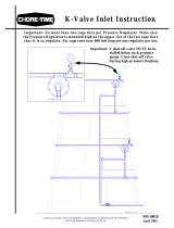
Apply thread sealant (one approved for plastic fittings) or Teflon tape to the 3/4 inch threaded outlet of the regulator and
thread on the Part no. 8160 adapter. Use PVC cement to attach the P/N. 8074 adapter or P/N 25098 flexible hose attachment
to the inlet of the regulator (positioned as necessary for connection to the inlet water supply pipe). Also attach the P/N. 9062
adapter to the stand tube/air breather port on the top of the regulator (be careful not to get glue inside the regulator). Cut a
piece of P/N. 8083 pipe long enough to extend the P/N. 8137 union out past the regulator body. This allows the regulator,
with the stand tube removed, to be unscrewed from the P/N. 8160 adapter, should removal be necessary. Glue the pipe into
the adapter and the P/N. 8137 union. After the regulator assembly is attached to the nipple line the connection can be
completed from the P/N. 8137 union to the inlet water supply. See Figure 1.
Figure 1. Cage Regulator Assembly
.
*For connections with Flexible Hose.
Item Description Part No.
1 Cap, Ass’y Breather 45703
2 Fitting, .75-11.5 NH Adapt 25098
3 Pipe, .50 x 19.88 Clear PVC 38250-1
4 Ball,.50 Blue Polypropylene 37142
5 Adapt, PVC Male .75 x .50 MTXS 9063
6 Adapt, Female .75 x .50 S x S 9062
7 Ell, PVC .75 X .50 S X S 8074
8 Union, .75 PVC S x FT 8137
9 Adapt, Female PVC .75 S x FT 8160
10 Nipple Line *****
11 Pipe, .75 PVC SDR (Cut to length) 8083-10
*12 Fitting, .75-11.5 NH Male Adapt 25098
10
9
6
4
3
1
2
5
7
8
7
11
8
To Cage Row To Water Supply
12
INLET
THREADED
OUTLET
MW1642AJanuary 2004

Installation VOLUMATIC™ WATER REGULATOR
2
MW1642A
Installation
( See Figure 2.)
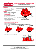
Each pressure regulator is capable of supplying one tier (two lines) up to 600 feet (182.8 meters). Systems over 600 feet
(182.8 meters) require two inlet assemblies per tier (one per line).
The regulator assemblies should be mounted on one side of the cage row in a location where it can be easily reached for
adjustment from the aisle and does not interfere with the other equipment (DBS system, egg belts, belt take ups, feeding
system etc.). Installation of the regulator assemblies should not be attempted until the location of all other equipment is
established. Also the regulator assemblies should be located so they are protected from damage.
The height of the stand tube/air breathers must also be taken into consideration when positioning the regulator assemblies. It
is important to be able to maintain this height so that the full operating range of the regulator can be utilized.
It is important to install the regulator in a manner which, with the stand tube/air breather removed, will allow the regulator
assembly to be turned off the nipple pipe line, should removal become necessary.
The regulator assemblies may be located in a variety of locations depending on the installation, operation and location of
other equipment. Additional plumbing components may be required.
It is also recommended that the regulator assembly is equal to or slightly higher than the nipple water line to aid in the
removal of unwanted air.
The connection between the regulator and the supply can be “rigidly plumbed” with the 3/4 inch (P/N. 8083-10) hook up
pipe provided. Flexible hose can also be used for this connection but it and the connectors must be of high quality and rated
for the incoming water pressure.

VOLUMATIC™ WATER REGULATOR Installation
MW1642A
3
Figure 2. Installation Layout.
Inlet Water Supply
Inlet Water Supply
Inlet Water Supply
2
3
1
7
8141, Ell,.75 PVC SXS
Rigidly Plumbed Water Supply
Under 600 Ft (182.9 M) One
Regulator Per Tier
Cage Row
Inlet Water Supply
8141, Ell,.75 PVC SXS (Top or bottom tier)
Or
7538, Tee,.75 PVC SXSXS
7538, Tee,.75 PVC SXSXS
Over 600 Ft (182.9 M) Two
Regulators Per Tier
Cage Row
7538, Tee,.75 PVC SXSXS (Top or bottom tier)
OR
7536, Cross,PVC .75 Slip
Inlet Water Supply
3
4
5
6
5
1
2
Cage Row
Over 600 Ft (182.9 M) Two
Regulators Per Tier
7538, Tee,.75 PVC SXSXS
Cage Row
Flexible Hose Water Supply
Under 600 Ft (182.9 M) One
Regulator Per Tier
8141, Ell,.75 PVC SXS
Item Part No. Description
1 8160 Adapt, Female PVC .75 S X FT.
2 ---- Stand Tube Port
3 42400-11 Reg, Cage Watering Man Std.
4 8074 Ell, PVC .75 X .50 S X S
5 8083-10 Pipe, .75 X 120 PVC SDR (Cut To Length)
6 8137 Union, .75 PVC S X S
7 25098 Fitting, .75-11.5 NH Male Adapter

Operation VOLUMATIC™ WATER REGULATOR
4
MW1642A
Operation
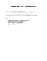
The VOLUMATIC™ Water Regulator can be shut off by turning the selector knob clockwise until it stops. To turn on the
regulator (normal operation) turn the selector to the center position. To put the regulator into Flush Mode, turn the selector
knob counter clockwise until it stops. To adjust the water column turn the manual adjustment knob on the bottom of the
regulator clockwise (+) to increase the pressure and counter-clockwise (-) to decrease the pressure.
Caution: When using a hose end flush arrangement be sure the outlet valve at the end of the nipple line is opened before
flushing the regulator. Excessive back pressure can damage the regulator.
Caution: When increasing the water column, as soon as resistance is noted, stop turning the manual adjustment knob or
damage to the regulator will occur.
Figure 3. Regulator Operations
Optimum incoming pressure is 25 - 35 PSI (172 - 241 kPa). Operation of the Volumatic™ water regulator at higher
pressures can shorten the life of the regulator seat. For pressures higher than the recommended range a water pressure
reducing valve should be installed on the inlet water supply.
PDS™-Pneumatic Drinking System Regulators
The Chore-Time PDS™, Volumatic™ regulators are designed so that if the air pressure to the regulators is lost, a “default”
water column is maintained and the water supply to the birds is uninterrupted.
The PDS regulator’s water column height is adjusted at the PDS control unit and therefore does not have a manual
adjustment knob but all the other functions discussed above for the standard Volumatic regulator apply to the PDS unit (on,
off and flush).
The #42400-12 regulator uses the #42394 spring, which provides a default water column of approximately 3 to 4 inch (7.6 to
10.2cm). This regulator is used for Chore-Time brood-grow nipple installations using the PDS system.
The #42400-14 regulator uses the #47685 spring, which provides a default water column of approximately 7 to 8 inch (17.8
to 20.3cm). This regulator is used for Chore-Time layer nipple installations using the PDS system.
The default water column values above are based on a normal 25-35 psi incoming water pressure and may vary with
incoming water pressure.
For more information on the PDS system and for installation and operation instructions refer to the “12-32 Station PDS™
Control Manual” (#MW1812).
Item Description
1 Outlet
2 Stand Tube Port
3 Adjustment Knob (On Bottom)
4 Selector Knob
5 Regulator “Off” Indicator
6 Water Column Increase Indicator (+)
7 Regulator “On” Indicator
8Inlet
9 Regulator “Flush” Indicator
10 Water Column Decrease Indicator (-)
2
1
10
9
8
7
6
5
4
3

VOLUMATIC™ WATER REGULATOR Parts Listing
MW1642A
5
Parts Listing
Volumatic™ Water Regulator For
Cage Systems
PDS™ and Manual Adjustment
Part No. 42400-11, 42400-12, 42400-14
*Item 21 for Part No. 42400-11
(Std.-Manual adj.)
*Item 22 for Part No. 42400-14
(Layer-PDS adj.)
*Item 23 for Part No. 42400-12
(Brood grow-PDS adj.)
**These components may be ordered as an
assembly under Part No. 42188.
Item Description Part No.
1 #6-20 x 5/8 Hex Washer Head Screw 44946
2 Shroud 42390
3 Selector Knob 42178
4 1.362 I.D. x .103 Wide O-Ring 42389
5 O-Ring 29118
6 Inlet Orifice 42190
7 Bushing 42391
8 Regulator Top Half 42174
9 Seat Holder Cap 42176
10 #6-20 x 5/8 Pan Head Screw 42386
11 Barrel 42172
12 Top Diaphragm Plate 42182
13 Seat Holder Sleeve 42187
14 .780 I.D. x 2.8 Long Spring 42392
15 Seat Holder 42189
**16 Seat, CT Regulator Viton 48225
**17 Cup, CT Regulator Seat 42199
18 Diaphragm Center Support 42186
19 Diaphragm 42181
20 Diaphragm Plate 42177
*21 Spring, .780 I.D x 2.77 L x .063 42393
*22 Spring, .780 I.D. x 2.8 L x .105 PDS 42394
*23 Spring, 3.76 Long Layer PDS 47685
24 Regulator Bottom Half (PDS Only) 42179
25 Regulator Bottom Half 42180
26 Follower 42183
27 Adjustment Knob 42184
28 #8-18 x 2-1/2" Pan Head Screw 42387
29 Knob Retainer 42173
30 Hose Barb (PDS Only) 44759
31 CT Regulator Seat Installation Tool 48688

Made to work.
Built to last.
Contact your nearby Chore-Time distributor or representative for additional parts and information.
CTB Inc.
P.O. Box 2000 • Milford, Indiana 46542-2000 • U.S.A.
Phone (574) 658-4101 • Fax (800) 333-4191
Email: [email protected]om • Internet: http//www.choretime.com
Printed in the U.S.A.
/