Page is loading ...

STEADI-FLOW
®
& RELIA-FLOW
®
Nipple Drinking System
Installation and Operators Manual
MW2392 BApril 2013

Warranty STEADI-FLOW® & RELIA-FLOW®
2
MW2392 B
Chore-Time, a division of CTB, Inc., (“Chore-Time”), warrants each new CHORE-TIME® product
manufactured by it to be free from defects in material or workmanship for one (1) year from and after the date of
initial installation by or for the original purchaser. If such a defect is found by Chore-Time to exist within the one-
year period, the Chore-Time will, at its option, (a) repair or replace such product free of charge, F.O.B. the factory
of manufacture, or (b) refund to the original purchaser the original purchase price, in lieu of such repair or
replacement. Labor costs associated with the replacement or repair of the product are not covered by the
Manufacturer.
Conditions and Limitations
1. The product must be installed by and operated in accordance with the instructions published by the
Manufacturer or Warranty will be void.
2. Warranty is void if all components of the system are not original equipment supplied by the Manufacturer.
3. This product must be purchased from and installed by an authorized distributor or certified representative
thereof or the Warranty will be void.
4. "Malfunctions or failure resulting from misuse, abuse, mismanagement, negligence, alteration, accident, or
lack of proper maintenance, or from lightning strikes, electrical power surges or interruption of electricity
shall not be considered defects under the Warranty. Corrosion, material deterioration and/or equipment
malfunction caused by or consistent with excessive additions of chemicals, minerals, sediments or other
foreign elements with the product shall not be considered defects under the Warranty."
5. This Warranty applies only to systems for the care of poultry and livestock. Other applications in industry
or commerce are not covered by this Warranty.
Chore-Time shall not be liable for any Consequential or Special Damage which any purchaser may suffer or
claim to suffer as a result of any defect in the product. “Consequential” or “Special Damages” as used herein
include, but are not limited to, lost or damaged products or goods, costs of transportation, lost sales, lost orders,
lost income, increased overhead, labor and incidental costs and operational inefficiencies.
THIS WARRANTY CONSTITUTES THE MANUFACTURER’S ENTIRE AND SOLE WARRANTY AND
THIS MANUFACTURER DISCLAIMS ANY AND ALL OTHER WARRANTIES, INCLUDING, BUT NOT
LIMITED TO, EXPRESS AND IMPLIED WARRANTIES AS TO MERCHANTABILITY, FITNESS FOR
PARTICULAR PURPOSES SOLD AND DESCRIPTION OR QUALITY OF THE PRODUCT FURNISHED
HEREUNDER.
Chore-Time Distributors are not authorized to modify or extend the terms and conditions of this Warranty in any
manner or to offer or grant any other warranties for CHORE-TIME® products in addition to those terms expressly
stated above. An officer of CTB, Inc. must authorize any exceptions to this Warranty in writing. Chore-Time
reserves the right to change models and specifications at any time without notice or obligation to improve previous
models.
Effective: August 2008
Chore-Time
A Division of CTB, Inc.
410 N. Higbee Street • Milford, Indiana 46542 • U.S.A.
Phone (574) 658-4101 • Fax (877) 730-8825
E-mail: poultry@choretime.com • Internet: www.choretimepoultry.com
Thank You
The employees of CTB, Inc. would like to thank your for your recent Chore-Time purchase. If a problem should
arise, your Chore-Time distributor can supply the necessary information to help you.
Warranty

Contents
Topic Page
MW2392 B
3
Warranty. . . . . . . . . . . . . . . . . . . . . . . . . . . . . . . . . . . . . . . . . . . . . . . . . . . . . . . . . . . . . . . . . . . . . . .2
Conditions and Limitations. . . . . . . . . . . . . . . . . . . . . . . . . . . . . . . . . . . . . . . . . . . . . . . . . . . . . . . . . . . . . . 2
About This Manual. . . . . . . . . . . . . . . . . . . . . . . . . . . . . . . . . . . . . . . . . . . . . . . . . . . . . . . . . . . . . . .5
Safety Information . . . . . . . . . . . . . . . . . . . . . . . . . . . . . . . . . . . . . . . . . . . . . . . . . . . . . . . . . . . . . . .5
Safety Instructions . . . . . . . . . . . . . . . . . . . . . . . . . . . . . . . . . . . . . . . . . . . . . . . . . . . . . . . . . . . . . . . 6
Follow Safety Instructions . . . . . . . . . . . . . . . . . . . . . . . . . . . . . . . . . . . . . . . . . . . . . . . . . . . . . . . . . . . . . . 6
Decal Descriptions . . . . . . . . . . . . . . . . . . . . . . . . . . . . . . . . . . . . . . . . . . . . . . . . . . . . . . . . . . . . . . . . . . . . 6
DANGER: Moving Auger. . . . . . . . . . . . . . . . . . . . . . . . . . . . . . . . . . . . . . . . . . . . . . . . . . . . . . . . . . . 6
DANGER: Electrical Hazard . . . . . . . . . . . . . . . . . . . . . . . . . . . . . . . . . . . . . . . . . . . . . . . . . . . . . . . . 6
CAUTION: . . . . . . . . . . . . . . . . . . . . . . . . . . . . . . . . . . . . . . . . . . . . . . . . . . . . . . . . . . . . . . . . . . . . . . 6
General. . . . . . . . . . . . . . . . . . . . . . . . . . . . . . . . . . . . . . . . . . . . . . . . . . . . . . . . . . . . . . . . . . . . . . . . . 6
Support Information . . . . . . . . . . . . . . . . . . . . . . . . . . . . . . . . . . . . . . . . . . . . . . . . . . . . . . . . . . . . . . . . . . . 6
Tools for Installation . . . . . . . . . . . . . . . . . . . . . . . . . . . . . . . . . . . . . . . . . . . . . . . . . . . . . . . . . . . . . 7
General Information. . . . . . . . . . . . . . . . . . . . . . . . . . . . . . . . . . . . . . . . . . . . . . . . . . . . . . . . . . . . . . 7
Manufacturer’s Recommendations: Birds per Nipple . . . . . . . . . . . . . . . . . . . . . . . . . . . . . . . . . . . . . . . . . 8
Planning the System layout . . . . . . . . . . . . . . . . . . . . . . . . . . . . . . . . . . . . . . . . . . . . . . . . . . . . . . . .9
Preferred Layout . . . . . . . . . . . . . . . . . . . . . . . . . . . . . . . . . . . . . . . . . . . . . . . . . . . . . . . . . . . . . . . . . . . . . . 9
Alternate Layout #1 . . . . . . . . . . . . . . . . . . . . . . . . . . . . . . . . . . . . . . . . . . . . . . . . . . . . . . . . . . . . . . . . . . . 9
Alternate Layout #2 . . . . . . . . . . . . . . . . . . . . . . . . . . . . . . . . . . . . . . . . . . . . . . . . . . . . . . . . . . . . . . . . . . .10
Suspension System Installation . . . . . . . . . . . . . . . . . . . . . . . . . . . . . . . . . . . . . . . . . . . . . . . . . . . . 11
Assembling and Hanging the Water Line . . . . . . . . . . . . . . . . . . . . . . . . . . . . . . . . . . . . . . . . . . . 13
Suspend Water Lines . . . . . . . . . . . . . . . . . . . . . . . . . . . . . . . . . . . . . . . . . . . . . . . . . . . . . . . . . . . . . . . . . .13
Install Coupling Assembly . . . . . . . . . . . . . . . . . . . . . . . . . . . . . . . . . . . . . . . . . . . . . . . . . . . . . . . . . . . . . .13
Mid-Line Stand Tube . . . . . . . . . . . . . . . . . . . . . . . . . . . . . . . . . . . . . . . . . . . . . . . . . . . . . . . . . . . . . . . . . .14
Optional Mid Line Shut-Off Valve: . . . . . . . . . . . . . . . . . . . . . . . . . . . . . . . . . . . . . . . . . . . . . . . . . . .14
Optional Slope Compensator: . . . . . . . . . . . . . . . . . . . . . . . . . . . . . . . . . . . . . . . . . . . . . . . . . . . . . . . .15
Outlet Assembly . . . . . . . . . . . . . . . . . . . . . . . . . . . . . . . . . . . . . . . . . . . . . . . . . . . . . . . . . . . . . . . . . . . . . .15
Regulator Assembly - VOLUMATIC™ . . . . . . . . . . . . . . . . . . . . . . . . . . . . . . . . . . . . . . . . . . . . . . . . . . .16
Regulator Operation Modes. . . . . . . . . . . . . . . . . . . . . . . . . . . . . . . . . . . . . . . . . . . . . . . . . . . . . . . . . .16
Regulator Guidelines. . . . . . . . . . . . . . . . . . . . . . . . . . . . . . . . . . . . . . . . . . . . . . . . . . . . . . . . . . . . . . .16
Filter Control Panel Installation. . . . . . . . . . . . . . . . . . . . . . . . . . . . . . . . . . . . . . . . . . . . . . . . . . . 17
Flushable Filter Control Panel Installation . . . . . . . . . . . . . . . . . . . . . . . . . . . . . . . . . . . . . . . . . . 17
Anti-Roost Installation. . . . . . . . . . . . . . . . . . . . . . . . . . . . . . . . . . . . . . . . . . . . . . . . . . . . . . . . . . . 19
Installing the Flush System . . . . . . . . . . . . . . . . . . . . . . . . . . . . . . . . . . . . . . . . . . . . . . . . . . . . . . . 21
PDS™ Flush Control . . . . . . . . . . . . . . . . . . . . . . . . . . . . . . . . . . . . . . . . . . . . . . . . . . . . . . . . . . . . 22
Parts Listing . . . . . . . . . . . . . . . . . . . . . . . . . . . . . . . . . . . . . . . . . . . . . . . . . . . . . . . . . . . . . . . . . . . 23
Filter Control Panel with Step Regulator . . . . . . . . . . . . . . . . . . . . . . . . . . . . . . . . . . . . . . . . . . . . . . . . . . .23
Flush able Filter Control Panel. . . . . . . . . . . . . . . . . . . . . . . . . . . . . . . . . . . . . . . . . . . . . . . . . . . . . . . . . . .24
Low Pressure: 36802-1 . . . . . . . . . . . . . . . . . . . . . . . . . . . . . . . . . . . . . . . . . . . . . . . . . . . . . . . . . . . . .24
High Pressure: 36802-2 . . . . . . . . . . . . . . . . . . . . . . . . . . . . . . . . . . . . . . . . . . . . . . . . . . . . . . . . . . . . .24
Stand Tube Outlet Assembly . . . . . . . . . . . . . . . . . . . . . . . . . . . . . . . . . . . . . . . . . . . . . . . . . . . . . . . . . . . .25
Manual Adjustment VOLUMATIC™ Regulator Assembly . . . . . . . . . . . . . . . . . . . . . . . . . . . . . . . . . . . .26
PDS™ Controlled Regulator Assembly . . . . . . . . . . . . . . . . . . . . . . . . . . . . . . . . . . . . . . . . . . . . . . . . . . . .28
Nipple Line Assembly and Components . . . . . . . . . . . . . . . . . . . . . . . . . . . . . . . . . . . . . . . . . . . . . . . . . . .30

Contents - continued
Topic Page
4
MW2392 B
Slope Compensator Assembly . . . . . . . . . . . . . . . . . . . . . . . . . . . . . . . . . . . . . . . . . . . . . . . . . . . . . . . . . . .32
Mid Line Stand Tube Assembly. . . . . . . . . . . . . . . . . . . . . . . . . . . . . . . . . . . . . . . . . . . . . . . . . . . . . . . . . .32
Miscellaneous Kits and Components . . . . . . . . . . . . . . . . . . . . . . . . . . . . . . . . . . . . . . . . . . . . . . . . . . . . . .33
Nipple Waterer Mini Drinker: 35412 . . . . . . . . . . . . . . . . . . . . . . . . . . . . . . . . . . . . . . . . . . . . . . . . . .34
Miscellaneous Hose Components . . . . . . . . . . . . . . . . . . . . . . . . . . . . . . . . . . . . . . . . . . . . . . . . . . . . .34
Mid Line Shut-Off Kit: 29658. . . . . . . . . . . . . . . . . . . . . . . . . . . . . . . . . . . . . . . . . . . . . . . . . . . . . . . .34
Mid Line Shut-Off Kit with Flush. . . . . . . . . . . . . . . . . . . . . . . . . . . . . . . . . . . . . . . . . . . . . . . . . . . . .35
Water Medicator . . . . . . . . . . . . . . . . . . . . . . . . . . . . . . . . . . . . . . . . . . . . . . . . . . . . . . . . . . . . . . . . . .35
Water Meters . . . . . . . . . . . . . . . . . . . . . . . . . . . . . . . . . . . . . . . . . . . . . . . . . . . . . . . . . . . . . . . . . . . . .35
Suspension System Components:. . . . . . . . . . . . . . . . . . . . . . . . . . . . . . . . . . . . . . . . . . . . . . . . . . . . . . . . .36
CHORE-TIME Nipple Watering Quick Reference Sheet . . . . . . . . . . . . . . . . . . . . . . . . . . . . . . 38
Operational Guidelines . . . . . . . . . . . . . . . . . . . . . . . . . . . . . . . . . . . . . . . . . . . . . . . . . . . . . . . . . . 39
Troubleshooting Guidelines. . . . . . . . . . . . . . . . . . . . . . . . . . . . . . . . . . . . . . . . . . . . . . . . . . . . . . . 39
Guide to Cleaning Water Lines. . . . . . . . . . . . . . . . . . . . . . . . . . . . . . . . . . . . . . . . . . . . . . . . . . . . 40
Standard Cleaning Procedure . . . . . . . . . . . . . . . . . . . . . . . . . . . . . . . . . . . . . . . . . . . . . . . . . . . . . . . . . . . .40
Regular Maintenance . . . . . . . . . . . . . . . . . . . . . . . . . . . . . . . . . . . . . . . . . . . . . . . . . . . . . . . . . . . . . . . . . .40
End of Grow Out Cleaning. . . . . . . . . . . . . . . . . . . . . . . . . . . . . . . . . . . . . . . . . . . . . . . . . . . . . . . . . . . . . .40
After Administering Vitamins, Medication or other Chemicals. . . . . . . . . . . . . . . . . . . . . . . . . . . . . . . . . .40
Between Flocks. . . . . . . . . . . . . . . . . . . . . . . . . . . . . . . . . . . . . . . . . . . . . . . . . . . . . . . . . . . . . . . . . . . . . . .40
Water Quality . . . . . . . . . . . . . . . . . . . . . . . . . . . . . . . . . . . . . . . . . . . . . . . . . . . . . . . . . . . . . . . . . . 41
Hardness . . . . . . . . . . . . . . . . . . . . . . . . . . . . . . . . . . . . . . . . . . . . . . . . . . . . . . . . . . . . . . . . . . . . . . . . . . . .41
Iron . . . . . . . . . . . . . . . . . . . . . . . . . . . . . . . . . . . . . . . . . . . . . . . . . . . . . . . . . . . . . . . . . . . . . . . . . . . . . . . .41
Iron Bacteria . . . . . . . . . . . . . . . . . . . . . . . . . . . . . . . . . . . . . . . . . . . . . . . . . . . . . . . . . . . . . . . . . . . . . . . . .41
Acid Water . . . . . . . . . . . . . . . . . . . . . . . . . . . . . . . . . . . . . . . . . . . . . . . . . . . . . . . . . . . . . . . . . . . . . . . . . .41
Aggressive/Corrosive Water. . . . . . . . . . . . . . . . . . . . . . . . . . . . . . . . . . . . . . . . . . . . . . . . . . . . . . . . . . . . .41
Taste and Odor . . . . . . . . . . . . . . . . . . . . . . . . . . . . . . . . . . . . . . . . . . . . . . . . . . . . . . . . . . . . . . . . . . . . . . .41
Hydrogen Sulfide . . . . . . . . . . . . . . . . . . . . . . . . . . . . . . . . . . . . . . . . . . . . . . . . . . . . . . . . . . . . . . . . . . . . .41
Sand, Silt or Sediment . . . . . . . . . . . . . . . . . . . . . . . . . . . . . . . . . . . . . . . . . . . . . . . . . . . . . . . . . . . . . . . . .41

STEADI-FLOW® & RELIA-FLOW® About This Manual
MW2392 B
5
The intent of this manual is to help you in two ways. One is to follow step-by-step in the order of assembly of your
product. The other way is for easy reference if you have questions in a particular area.
Important: Read ALL instructions carefully before starting construction.
Important: Pay particular attention to all SAFETY information.
• Metric measurements are shown in millimeters and in brackets, unless otherwise specified. “"” equals inches
and “'” equals feet in English measurements.
Examples:
1" [25.4]
4' [1 219]
• Optional equipment contains necessary instructions for assembly or operation.
• Very small numbers near an illustration (i.e.,
1257-48) are identification of the graphic, not a part number.
Note: The original, authoritative version of this manual is the English version produced by CTB, Inc. or any of its
subsidiaries or divisions, (hereafter collectively referred to as "CTB"). Subsequent changes to any manual made
by any third party have not been reviewed nor authenticated by CTB. Such changes may include, but are not
limited to, translation into languages other than English, and additions to or deletions from the original content.
CTB disclaims responsibility for any and all damages, injuries, warranty claims and/or any other claims
associated with such changes, inasmuch as such changes result in content that is different from the authoritative
CTB-published English version of the manual. For current product installation and operation information,
please contact the customer service and/or technical service departments of the appropriate CTB subsidiary or
division. Should you observe any questionable content in any manual, please notify CTB immediately in writing
to: CTB Legal Department, P.O. Box 2000, Milford, IN 46542-2000 USA.
Caution, Warning and Danger Decals have been placed on the equipment to warn of potentially dangerous
situations. Care should be taken to keep this information intact and easy to read at all times. Replace missing or
damaged safety decals immediately.
Using the equipment for purposes other than specified in this manual may cause personal injury and/or damage to
the equipment.
Safety–Alert Symbol
This is a safety–alert symbol. When you see this symbol on your equipment, be alert to the
potential for personal injury. This equipment is designed to be installed and operated as safely
as possible...however, hazards do exist.
Understanding Signal Words
Signal words are used in conjunction with the safety–alert symbol to identify the severity of the warning.
DANGER indicates an imminently hazardous situation which, if not avoided, WILL result in death or
serious injury.
WARNING indicates a potentially hazardous situation which, if not avoided, COULD result in death or
serious injury.
CAUTION indicates a hazardous situation which, if not avoided, MAY result in minor or moderate
injury.
About This Manual
Safety Information

Safety Instructions STEADI-FLOW® & RELIA-FLOW®
6
MW2392 B
Follow Safety Instructions
Carefully read all safety messages in this manual and on your equipment safety signs. Follow recommended
precautions and safe operating practices.
Keep safety signs in good condition. Replace missing or damaged safety signs.
Decal Descriptions
DANGER: Moving Auger
This decal is placed on the Panel Weldment.
Severe personal injury will result, if the electrical power is not
disconnected, prior to servicing the equipment.
DANGER: Electrical Hazard
Disconnect electrical power before inspecting or servicing equipment
unless maintenance instructions specifically state otherwise.
Ground all electrical equipment for safety.
All electrical wiring must be done by a qualified electrician in accordance
with local and national electric codes.
Ground all non-current carrying metal parts to guard against electrical
shock.
With the exception of motor overload protection, electrical disconnects and
over current protection are not supplied with the equipment.
CAUTION:
Use caution when working with the Auger—springing Auger may cause personal
injury.
Support Information
The Chore-Time Nipple Watering Systems are designed to provide water to poultry types. Using this equipment
for any other purpose or in a way not within the operating recommendations specified in this manual will void the
warranty and may cause personal injury.
This manual is designed to provide comprehensive planning and installation information. The Table of Contents
provides a convenient overview of the information in this manual.
Safety Instructions
General
Manboot 3/98

STEADI-FLOW® & RELIA-FLOW® Tools for Installation
MW2392 B
7
It is extremely important to maintain good water quality. Good water quality maximizes performance of the
equipment, minimizes maintenance and repair, and increases the life of the system. The water should be free of
foreign particles.
Pump the well prior to hookup of the system to clear sand, mud, or debris. CHORE-TIME recommends a water
test by a reputable water treatment company in the area. Water treatment and/or extra filtration may be required,
depending on the water test results.
Chore-Time recommends an incoming water pressure between 25 psi [172.4 kPa] minimum and 35 psi [241.4
kPa] maximum for use with the 9275 or 36802-2 control panel.
For an incoming water pressure between 40 psi [275.9 kPa] minimum and 125 psi [862 kPa] maximum it is
recommended to use a 35308 step regulator. A pressure of 45 psi [310.3 kPa] is best. It is recommended to use
the step regulator for regulating the water pressure through the control panel at 25 psi [172.4 kPa] up to a
maximum of 35 psi [241.4 kPa].
CHORE-TIME recommends a minimum incoming water pressure of 3 psi [21 kPa] for gravity feed systems. To
obtain this minimum pressure the water level in the water tank should be maintained 8’ [2.4 m] above the nipple
line. CHORE-TIME recommends a Maximum line length of 250’ [76 m] for a gravity feed system.
For every 28" [711 mm] drop in height, water pressure increases one pound. Measure the operating pressure at the
water line height.
Incoming water supply should be at least a 1" [25 mm] diameter incoming line (preferably PVC) from a single
well. If there are two or more supply wells, the supply line should be larger. Other factors such as, the distance
from the well(s) to the filter control panel and other equipment which requires water could demand larger lines.
The suspension system must be correctly installed to insure proper operation of the system. This manual includes
the suspension installation information.
The CHORE-TIME nipple drinker is available with nipples spaced 6" [150 mm], 8" [200 mm], 10" [250 mm], 12"
[300 mm], 15" [380 mm], 20" [508 mm], or 24" [610 mm] on the 10’ [3 m] pipe.
Water lines up to 500’ [152 m] may be supplied using (1) regulator assembly. Water lines over 500’ [152 m] must
be split in the center of the house and supplied with (2) regulator assemblies. However the management of the
lines over 250’ [76 m] becomes more critical. They must be kept very level, flushed, and cleaned several times
per flock.
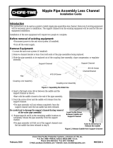
The CHORE-TIME nipple drinker is available with the standard support channel for broiler applications. The
Chore-Time nipple drinker is also available with the heavy support channel for pullets and breeders. Figure 1
shows the difference between the standard and heavy support channel with the standard and button nipple
assemblies in the STEADI-FLOW
®
drinkers. Figure 2 shows the difference between the standard and heavy
support channel and button nipple assemblies in the RELIA-FLOW
®
drinkers.
Tools for Installation
1 Regular Screwdriver 6 Bolt Cutters or Hack Saw
2 Locking Pliers 7 PVC Cleaning Solvent
3 File 8 Electrical Drill and Drill Bits
4 Saw to cut PVC Tubes 9 Another Person to help
5 Screw-Hook Driver
General Information

General Information STEADI-FLOW® & RELIA-FLOW®
8
MW2392 B
Figure 1. Various STEADI-FLOW
®
Drinker Styles
Figure 2. Various RELIA-FLOW
®
Drinker Styles
Manufacturer’s Recommendations: Birds per Nipple
For breeders, place the water line INSIDE The ULTRAFLO
®
Breeder Feeder Loop.
For a pan feeder system, place the water line within three feet [1m] of the feed line.
For pullets, it is ideal to place water lines on either side of the feed lines within 3 ft. [1m].
In areas where house temperature will reach 100°F (40°C) for sustained periods and no evaporative
cooling or tunnel ventilation is used, an anti-roost system is needed.
Recommended incoming pressure of
25 to 35 psi [172 to 241 kPa].
Type Recommended Number birds per Nipple Recommended Options
Broiler 30 for day old chicks
10-15 for grow-out
Standard channel-Standard Flow (Button options) or Standard
channel-Hi Flow w/catch cup (Button options)
Breeder 8-10 for hot to warm climates
10-12 for warm to cool climates
Heavy Duty channel-standard-flow or
Heavy Duty channel High Flow w/catch cup (Hot climates Only)
Pullets 16-24 for day-old chicks
8-12 for grow out
Standard channel-Standard Flow
Poults 10-15 after brooding 6 wks or less-Standard channel-Standard flow
7-9 wks-Heavy Duty channel (Hi Flow w/Buttons recommended)
Standard
Support
Channel
Heavy Duty
Support
Channel
RELIA-FLOW
Nipple
Assembly
RELIA-FLOW
Button Nipple
Assembly
RELIA-FLOW
Nipple
Assembly
RELIA-FLOW
Button Nipple
Assembly
Standard
Support
Channel
Heavy Duty
Support
Channel
1186-100 8/04

STEADI-FLOW® & RELIA-FLOW® Planning the System layout
MW2392 B
9
The diagrams below reflect approved system layouts. Use these diagrams as guidelines. Your system layout may
be different.
Preferred Layout
Alternate Layout #1
Planning the System layout
1186-55 7/99
Outlet
Sight Tube
Outlet
Sight Tube
Outlet
Sight Tube
Outlet
Sight Tube
Outlet
Sight Tube
Outlet
Sight Tube
Outlet
Stand Tube
Outlet
Stand Tube
Inlet Inlet
Inlet Inlet
Garden Hose
Garden Hose
Recommended Maximum Length 250'
Curtain for Brood Area
Garden Hose (Flush Line)
Mid Line Stand Tube Kit (Needed for Lines Above 150' Long)


STEADI-FLOW® & RELIA-FLOW® Suspension System Installation
MW2392 B
11
The following installation instructions are for standard installations. For partial house brooding, the sections can
be winched separately or together. Install each section as a separate section.
1. Determine where the water line is to be installed. Mark a straight line on the ceiling or rafters at this point
using string or chalk line, or winch cable temporarily attached with staples or nails.
2. For installations using wood trusses, the standard screw hook or the optional ceiling hook may be used to
hold the pulley assemblies.
For installations using steel trusses, the ceiling hooks are available to hold the pulley assemblies.
Screw hook installations: Install screw hooks
along the line at 8’ [2.4 m] or 10’ [3 m]
intervals.
Screw the threads all the way in to prevent
bending. The opening of the hooks must point
away from the direction the cable pulls. See
Figure 3
Ceiling hook installations: Install ceiling
hooks along the line at 8’ [2.4 m] or 10’ [3 m]
intervals. If the ceiling hook is to be secured
with bolts or self-tapping screws, install as
shown in Figure 4. The ceiling hooks may be
welded in place, if desired, instead of bolting.
Note: If the distance the water line is to be
raised is greater than the distance
between the pulleys, offset the pulleys
from each other approximately 3" [75
mm].
3. After the screw hooks or ceiling hooks
have been secured to the trusses install
the pulley assemblies as shown in
Figures 3 & 4. Make sure the screw
hooks or ceiling hooks are pointing in
the proper direction (opposite the
winch).
4. Mount the split drum winch as shown
in Figure 6. Mount the winch to the
ceiling or on a 2 x 8” [50 x 200 mm]
board spanning at least two rafters for
support. Use at least (4) 1/4" lag
screws (not supplied) to secure winch
to support.
For systems less than 150’ [46 m], the
manual winch may be used in place of
the split drum winch.
Suspension System Installation
Screw Hook Opening
3/32" Cable or
1/8” Rope
[2 mm]
Figure 3. Screw Hook Installation
1186-76 11/2000
Secure with bolts and nuts
or self-tapping screws
Swivel Pulley
Figure 4. Ceiling Hook Installation
1186-77 11/2000
1/8" [3 mm] Winch Cable
Screw Hook Location
Drop Cable or Cord
Distance Water Line
is to be Raised
Distance of
Cable Travel
Figure 5. Offset the Screw/Ceiling Hooks

Suspension System Installation STEADI-FLOW® & RELIA-FLOW®
12
MW2392 B
5. Bolt the winch to the bracket, as shown in Figure 6.
Figure 6. Winch Mounting
6. Attach one end of the 3/16" [4.8 mm] cable to the winch as shown in Figure 7. Unroll the cable along the
length of the water line.
Figure 7. Cable Wrap on Drum
7. Cut a section of the 3/32" [2.3 mm] cable or cord for each suspension drop. The cable or cord should be
approximately three feet [91 cm] longer than the distance from the floor to the ceiling so that it can be
attached at the top and bottom.
Route the cable or cord around the swivel pulley and attach to the main cable, using a clamp.
8. Cable drop installations: Install an adjustment leveler on each drop line. See Figure 8.
Cord drop installations: Install a cord adjuster on each drop line. See Figure 8.
Helpful Hint:It may be necessary to fasten a weight to the end of the main cable to maintain tension while
connecting the drop lines, etc.
MW1186-78 11/2000
1/4" Lag Bolts
Winch
Secure the Winch to the Winch
Mounting Bracket using the supplied
Bolt, Washer, and Nut
Ceiling
Winch Mounting Bracket
MW928-4 11/91
1186-79 11/2000
Use the small hole
for 3/32" [2 mm]
Cable
Cable Adjustment
Hanger
Cord
Adjuster
Suspension
Hanger
Figure 8. Cable Drop Installation

STEADI-FLOW® & RELIA-FLOW® Assembling and Hanging the Water Line
MW2392 B
13
Raise the suspension to a convenient working height.
A nail apron may be used to carry hangers, connectors,
expansion joints, keys, adjustment levelers, or cord adjusters.
Figure 9 identifies several of the primary components used with
the nipple watering line.
Suspend Water Lines
Suspend the watering line every 8’ or 10’ [2.4 or 3 m] at the
suspension drops.
1.Route the suspension cable through the top hole of the
suspension hanger and around the cable adjuster as shown
in “Figure 8.” on page 12.
2.Assemble the suspension hanger over the support channel at
every suspension drop.
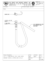
Install Coupling Assembly
Install coupling liner assembly on the end of the water pipe, as shown in Figure 10. Insert the pipe until it contacts
the stop rib inside the coupling liner assembly.
Note: It may be necessary to lubricate the inside of the coupling with soapy water to allow for easy
installation.
Insert the next pipe into the other end of the coupling liner assembly until the support channels meet.
Figure 10. Coupling Liner Assembly Installation
Make sure the water pipes are fully inserted into the coupling assembly.
Note: The support channels will be butted against each other when the coupling is properly installed.
Insert the key into the first support channel, as shown in Figure 11. Insert the tab of the key through the hole in
the second support channel. Once installed, bend the tab to secure it in place. This will prevent the water lines from
separating at the joints.
Note: When an anti-roost system is to be installed it is recommended to use the channel bracket in place
of the key.
Figure 11. Securing the Water Line together
Assembling and Hanging the Water Line
1186-80 11/2000
Cord Adjuster
Key
Coupler
Hanger
Cable Adjuster
Figure 9. Nipple Waterer Components
1186 81 11/2000
Support Channel
Coupling Liner Assembly

Assembling and Hanging the Water Line STEADI-FLOW® & RELIA-FLOW®
14
MW2392 B
Mid-Line Stand Tube
One mid-line stand tube is required for every 150’ [46 m] of nipple watering line, see Figure 12.
1.Insert the water pipe into the body.
2.The support channel will slide into the channels on the top of the body.
3.Secure the body to the support channel using the supplied 10-24 stainless steel screw and lock nut.
4.Use PVC cement to glue the male fitting to the top of the flexible tubing. Assemble the remaining
components of the stand tube.
5.Push the stand tube assembly on the mid line air remover or slope compensator vent tube and install the
adjustable clamp.
Figure 12. Mid Line Stand Tube Installation
Optional Mid Line Shut-Off Valve:
The mid line shut-off valve may be located at any convenient location along the water line, except next to a joint.
1.Determine the desired location for the mid line shut-off valve.
2.Use a flat screw driver to carefully pry 3 or 4 saddles away from the support channel. This will allow easy
access to the water pipe for cutting.
3.Use PVC pipe cutters to cut a section out of the water pipe. See Figure 13. The shut-off valve may be used as
a template to determine the required size of the cut.
4.Apply PVC cement to the couplers on the mid line shut-off valve assembly.
5.Install the mid line shut-off valve on the water line.
6.Reinstall the saddles previously loosened in the support channel.
Note: Chore-Time recommends installing a mid line stand tube at the first joint before a mid line shut-off
valve to insure proper air removal from the water line.
Figure 13. Mid Line Shut-Off Valve Installation
Mid-Line Stand Tube
Water Pipe
Body
Support Channel
10-24 Hardware
1186-83 4/2013
Glue Fitting to Tube
Breather Cap
Male Fitting
Flexible Tube
Spring
Adjustable Clamp
Support Channel
Saddle
Mid Line Shut Off Valve
Cut-Out Section of Water Pipe
Water Pipe
Water Flow
Water Flow

STEADI-FLOW® & RELIA-FLOW® Assembling and Hanging the Water Line
MW2392 B
15
Optional Slope Compensator:
The slope compensator is used in houses that have a gradual slope over the length of the system. The slope
compensator allows the water pressure to be re-adjusted along the line.
•The inlet end of the slope compensator must be at the top of the slope. Arrow must point in direction of
water flow. Do not attempt to push water uphill.
•The maximum amount of drop between the inlet assembly and the slope compensator, or between two
slope compensators, or between the slope compensator and the outlet assembly is 4 inches [100 mm].
See Figure 14.
•The maximum number of slope compensators used on any one water line is six.
•The maximum amount of slope over any water line is 28 inches [71 cm] of drop. See Figure 14.
Figure 14. Slope Compensator Assembly Installation
Outlet Assembly
The outlet end must be located within 6" [152 mm] of a suspension drop line. This may require adding an
additional suspension drop line or cutting the last section of water line to stop within 6" [152 mm] of an existing
drop line.
Install the outlet assembly, as shown in Figure 15.
1.Make sure the end of the water pipe is flush with the end of the support channel.
2.Make sure the hanger is properly oriented on the outlet assembly tee prior to securing the water line with
PVC cement.
3.Secure the hanger to the support channel, as shown in Figure 15. If the water line was shortened to terminate
under a suspension drop line, it may be necessary to drill a hole in the support channel for the 10-24 stainless
truss head screw and lock nut. The hanger may be used as a template to determine proper hole location.
4.Wrap threads of the 1/2" male adapter on stand tube assembly with sealant tape.
5.Thread the stand tube assembly into the outlet tee.
6.Use PVC cement to glue the male fitting to the top of the flexible tubing. Assemble the remaining
components of the stand tube.
7.Install stand tube and clamp by sliding the tube over the male adapter, tighten the adjustable clamp.
Figure 15. Outlet Assembly Installation
Cord Adjuster
Hanger
Support Channel
Hanger
Stand Tube Outlet Assembly
Water Pipe
Stand Tube Bracket
Glue Fitting to Tube
Breather Cap
Male Fitting
Flexible Tube
Spring
Adjustable Clamp

Assembling and Hanging the Water Line STEADI-FLOW® & RELIA-FLOW®
16
MW2392 B
Regulator Assembly - VOLUMATIC™
Assemble and install the regulator assembly, as shown in Figure 16.
1.Glue the included NH male adapter fitting or optional street ell and HN male adapter fitting to the inlet. Be
careful not to get glue inside the regulator.
2.Slide the outlet end over the watering pipe (it helps to wet the black outlet liner) and into the end of the
channel.
3.Slide the regulator bracket into the hole provided in the regulator and fasten into the hole provided in the
channel with the included #10-24 x 5/8'' hex washer head screw and #10-24 hex nut.
4.Use PVC cement to glue the male fitting to the top of the flexible tubing. Assemble the remaining
components of the stand tube.
5.Assemble the stand tube and clamp to the regulator by sliding the tube over the barbs and tightening the
adjustable clamp.
Figure 16. Regulator Assembly Components
Regulator Operation Modes
The VOLUMATIC™ Water Regulator can be shut off by turning the selector knob clockwise until it stops. To
turn on the regulator, turn the selector knob until it points to the ON position indicated on the regulator. To
activate the flush mode turn the selector knob fully counter-clockwise until it stops.
Regulator Guidelines
•Optimum incoming pressure is 25 to 35 psi [172 to 241 kPa].
•When flushing, make sure the outlet line is clear of restrictions. Excessive back pressure can damage the
regulator.
•When using the manual adjustment version of the regulator, the water column is set by turning the
manual adjustment knob on the bottom of the regulator in the direction shown on the regulator.
Important: When increasing the water column, as soon as resistance is noticed, stop turning
the manual adjustment knob or damage will occur.
NH Male
Adapter
Regulator Bracket
Stand Tube
Assembly
Stand Tube Float
Support Channel
Water Pipe
Adjustable Clamp
Regulator Bracket
NH Male
Adapter
Street Ell
Water Column
Adjustment
Operation
Selector Knob
Spring
Flexible
Tube
Male
Fitting
Breather
Cap
Glue Fitting to
Tube

STEADI-FLOW® & RELIA-FLOW® Filter Control Panel Installation
MW2392 B
17
The filter control panel is used to remove foreign material from the incoming water, and, if necessary, add
medication to the water.
The step down regulator and gauge assembly is used to reduce the water pressure supplying the filter control panel.
adjust the operating pressure as recommended in the Nipple Waterer Quick Reference Sheet. See page 38.
The filter control panel and step down regulator should be installed in a convenient location where incoming and
outgoing water supply lines can be easily run. The control panel must be out of the reach of birds.
The filter control panel is shipped secured to a mounting board. The mounting board and filter control panel should
be secured to wall or post using lag bolts (not supplied).
The step down regulator and gauge assembly is shipped un-assembled. Assemble the step down regulator and
gauge assembly components as specified in the instruction (MW1052) shipped with the kit.
Connect the step down regulator and gauge assembly to the filter control panel, as shown in Figure 6.
Figure 6. Control Panel Installation
(Optional alternative to the standard filter control panel)
The flushable filter control panel is used to remove foreign material from the incoming water, and, if necessary,
add medication to the water. This control panel features a filter that may be removed, cleaned, then reinstalled.
Two versions of the filter control panel are available.
The low pressure version is designed to accommodate gravity flow systems with 5 - 10 p.s.i [34.5 - 69.0 kPa]. Do
not exceed 15 p.s.i. [103.4 kPa] with this control panel, or damage will occur to the gauges.
Systems with 11+ p.s.i. [75.8+ kPa] should use the high pressure control panel and a step down regulator (order
separately).
The filter control panel should be installed in a convenient location where incoming and outgoing water supply
lines can be easily run. The control panel must be out of the reach of birds.
The filter control panel is shipped secured to a mounting board. The mounting board and filter control panel should
be secured to wall or post using lag bolts (not supplied).
The gauge assembly is shipped un-assembled. Assemble the gauge assembly components as specified in the
instruction (MW1052) shipped with the kit.
Filter Control Panel Installation
Flushable Filter Control Panel Installation
Filter Control Panel
Part Number 9275
Step Down Regulator
and Gauge Kit
Part Number 35308


STEADI-FLOW® & RELIA-FLOW® Anti-Roost Installation
MW2392 B
19
Pullet and breeder applications require the anti-roost system to be installed. This prevents the birds from setting
on the water line. Figure 7 shows an overview of the anti-roost system.
Figure 7. Anti-Roost System Overview
1. Make certain that an anchor plate with adjustment leveler is installed at the beginning and end of each anti-
roost line. See Figure 8.
2. When an anti-roost system is to be installed the channel bracket kit must be used in place of the key to
connect the channels together.
3. Install a hanger every 24" [610 mm]
4. Beginning at the first hanger, thread the training cable the full length of the anti-roost line. Allow
approximately 24" [610 mm] extra and cut the cable.
5. Create a small loop with the cable and a cable clamp.
6. Connect the cable loop to the adjustment leveler/anchor plate.
7. Install a spring on the adjustment leveler/anchor plate near the inlet assembly.
8. Pull the cable taught and create a small loop with the cable and a cable clamp.
9. Connect the cable to the spring.
10. The spring should be stretched to an overall length of approximately 8" [203 mm]. Adjust as required.
11. Repeat the above procedure on each of the anti-roost lines.
12. Optional Equipment: Secure the poultry trainer to a wall or post near the water line.
Chore-Time recommends wiring the poultry trainer into separate electrical circuit that can be switched at the
door.
Refer to the instructions supplied with the poultry trainer for wiring information.
Note: Make sure that the support channel is attached to ground (to insure proper operation of the poultry
trainer). See Figure 8.
It will be necessary to install a jumper wire at stand tube, inlet assemblies, etc., to insure the ground circuit.
See Figure 19.
Anti-Roost Installation

Anti-Roost Installation STEADI-FLOW® & RELIA-FLOW®
20
MW2392 B
Figure 8. Anti-Roost Components
Route To Ground
Only needed if Poultry
Trainer is used
Adjustment Lever
Tension Spring
Training Cable
Anchor Plate
Support Channel
Hanger
Ground Wire Jumper
Only needed if Poultry
Trainer is used
Mid Line Stand Tube
Channel Bracket
Cable Clamp
/