Page is loading ...

120 S. Glasgow Avenue
Inglewood, California 90301 U.S.A.
-195 / -197 / -198 HEATER KITS
9200 Specifications Tables
These kits are designed for the 9200 • 9500 • 6300 208 & 230 VAC Input power or 460 VAC Input power
• 6550 208 & 230 VAC Input power or 460 VAC Input power • 6555 230 VAC Input power
• 9000 208 & 230 VAC Input power or 460 VAC Input power • 9024 AC powered 230 VAC ONLY
• 9150 208 & 230 VAC Input power or 460 VAC Input power • 1601/1602/1603 208 & 230 VAC Input power or 460 VAC
Input power model gate operators. For cold weather climates where temperatures routinely drop below 10°F (-12°C).
A built-in thermostat will automatically control the temperature inside operator housing.
Find your “SPECIFIC” operator on the next 15 pages.
DoorKing Part Numbers:
1
9210 115 VAC
50 80 130 210
16.3
208 VAC
230 VAC
208 VAC
230 VAC
1
2
9210
9220
8.4
8.3
15.0
14.8
208 VAC
230 VAC
460 VAC
208 VAC
230 VAC
460 VAC
208 VAC
230 VAC
208 VAC
230 VAC
1
2
3
3
6.7
6.6
5
10.0
9.6
6.6
13.2
13.0
16.2
16.0
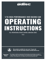
High voltage AC input wire size and distance limitations for a 9210 - 115 VAC with a heater.
High voltage AC input wire size and distance limitations for a 9200 - 208/230 VAC OR 460 VAC with a heater.
Installation on next page.
1
ø
Wire Size / Max Distance in Feet
Operator
and
Heater
Amps
ModelPhase
Motor
Horsepower Volts
180
210
100
110
270
300
800
180
210
610
130
150
110
120
12 AWG
290
330
160
180
430
480
1280
290
330
970
210
240
170
200
10 AWG
470
530
260
290
680
770
2040
460
530
1540
340
390
280
310
8 AWG
750
840
420
470
1090
1220
3240
730
840
2450
550
620
450
500
6 AWG
1601-197
1601-197
1601-197
1601-197
1601-197
1601-197
1601-198
1601-197
1601-197
1601-198
1601-197
1601-197
1601-197
1601-197
Heater Kit P/N
Wire Size / Max Distance in Feet
Operator
and
Heater
Amps
ModelPhase Horsepower Volts 12 AWG 10 AWG 8 AWG 6 AWG
1601-195
Heater Kit P/N
Note: Operator should have a “Dedicated 20 Amp” minimum circuit breaker at the power source.
1601-195 Kit
115 VAC Model
6.6 Amp
1601-197 Kit
208/230 VAC Models
3.3 Amp
1601-198 Kit
460 VAC Models
3.3 Amp
9210
9220
9235
9230/9240
1
ø
3
ø
High Voltage AC Input Power for the 9200 Gate Operator with a Heater
The 9200 draws significant power and should have a “Dedicated” circuit breaker at the power source.
If power wiring is greater than the maximum distance shown, it is recommended that a service feeder be installed. When large gauge wire is used,
a separate junction box must be installed for the operator connection. Wire run calculations are based on NEC 310.15(B)(16) with a maximum
voltage drop of 3%. These wire runs are a general guideline but it is highly suggested that individual calculations are made for your specific
installation as these distances may vary. Never run low voltage rated wire insulation in the same conduit as high voltage rated wire insulation.
Copyright 2020 DoorKing
®
, Inc. All rights reserved.
1601-167-G-11-20
1

Power
Wires
O
N
O
FF
Electronic Box
ON
OFF
DANGER
HOT!
WARNING
MOVING
GATE CAN CAUSE
Ope
ra
te
gate only w
h
e
n
ga
te ar
e
a
is i
n
si
g
h
t
a
n
d fr
e
e
o
f
p
eop
le
and
o
b
struc
ti
ons.
Do
n
ot al
low
c
hi
ldre
n to pl
a
y
in ga
te ar
e
a
o
r
o
pe
ra
te ga
te.
Do
n
ot sta
nd
in
g
a
te
pa
th
o
r
w
a
lk
thro
ug
h
p
ath wh
il
e
g
a
te is mov
ing.
Re
a
d owne
r’
s
m
anu
al
an
d sa
fety in
s
truc
tion
s.
SERIO
U
S INJ
UR
Y OR
DEAT
H
CL
ASS
CE
RT
I
FI
E
D T
O
CAN
/
CSA C2
2
.
2 NO.
2
47
CONF
ORMS
T
O
ANSI
/
UL
-
3
25
VEHICU
LAR GA
TE
O
PER
A
TO
R
HP
5
3
3
8
2
MODE
L
SE
RI
A
L
VOL
TS
PHASE
AMPS 6
0
Hz
MAX GAT
E
L
OA
D
DoorKi
ng,
I
nc
.
,
I
ngl
ewood, CA
Mounting Plate
1
2
3
Heater
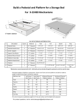
9200 Installation of Heater
Remove clear plastic electronic box cover. Remove the 3 locknuts
inside the electronic box to swing box open.
Bolt mounting plate to heater with 2 supplied bolts and nuts.
Slide heater into the gear reducer bracket as shown below and
bolt heater to the bracket with 2 supplied securing bolts.
Run the 2 power wires as shown below.
Keep wires away from the heater vents and make sure
wires do not get pinched in the electronic box’s folding hinge.
ON - Normal setting.
Automatically turns the
heater ON when the
temperature drops
below 40°F (4°C) inside
the operator, and turns
the heater OFF when
the temperature rises
above 55°F (13°C)
inside the operator.
Heater Switch
ON
OFF
OFF
- Turns
the heater off.
Hot
L1 L2 L3 L4 L5
Neu
115 VAC
208/230/460 VAC
1-Phase and 3-Phase
Hot Hot Hot
DANGER
HIGH VOLTAGE!
DANGER
HIGH VOLTAGE!
DANGER
HOT!
Connect the 2 heater power wires
according to operator AC power type.
Note: The gear reducer bracket may need to
be spread apart a little to get the heater to
slide in.
Older 9200s must have 2 holes drilled in the
gear reducer bracket for the securing bolts.
Power Connection
1601-197 Kit (208/230 VAC)
1601-198 Kit (460 VAC)
1601-195 Kit
G
ear
R
educer
Bracket
Lo
cknut
Lo
cknut
Lo
cknut
Power Wires
Clear Plastic Electronic Box Cover
Access Door
Securing
Bolts
L1 L2 L3 L4 L5
120 S. Glasgow Avenue
Inglewood, California 90301 U.S.A.
DoorKing Part Numbers
115 VAC Model
6.6 Amp
1601-195 Kit
208/230 VAC Models
3.3 Amp
1601-197 Kit
460 VAC Models
3.3 Amp
1601-198 Kit
Shut off the AC input power to the
operator from the circuit breaker.
Wire run tables on previous page.
1601-167-G-11-20
2

DoorKing Part Numbers:
208 VAC
230 VAC
460 VAC
5
3
9550/9555
16.2
16.1
9.7
High Voltage AC Input Power for the 9500 Gate Operator with a Heater
High voltage AC input wire size and distance limitations for a 9500 - 208/230 VAC OR 460 VAC with a heater.
Wire Size / Max Distance in Feet
Operator
and
Heater
Amps
Model Phase
Motor
Horsepower Volts
110
125
410
12 AWG
175
195
660
10 AWG
280
315
1050
8 AWG
450
500
1650
6 AWG
Heater Kit
P/N
208 VAC
230 VAC
460 VAC
1
24.4
22.4
12.5
n/a
n/a
270
100
120
430
160
190
700
260
310
1100
208 VAC
230 VAC
460 VAC
7
3
9570/9575
25.0
23.8
13.5
n/a
n/a
290
110
130
470
180
210
750
290
340
1200
208 VAC
230 VAC
460 VAC
1
35.0
32.0
17.0
n/a
n/a
200
n/a
n/a
320
110
130
510
180
210
820
208 VAC
230 VAC
460 VAC
10
3
9590/9595
29.3
26.3
15.3
n/a
n/a
260
90
120
410
150
190
660
250
300
1060
1601-197
1601-198
1601-197
1601-198
1601-197
1601-198
1601-197
1601-198
1601-197
1601-198
1601-197
1601-198
208 VAC
230 VAC
460 VAC
1
45.5
41.4
21.6
n/a
n/a
n/a
n/a
n/a
250
n/a
n/a
400
130
160
640
120 S. Glasgow Avenue
Inglewood, California 90301
U.S.A.
1601-197 Kit
208/230 VAC Models
3.3 Amp
1601-198 Kit
460 VAC Models
3.3 Amp
9500 Specifications Table
W
ARNING
M
O
V
I
NG
GA
T
E
C
A
N
C
A
US
E
O
p
e
r
a
t
e
g
a
t
e
o
n
ly
w
h
e
n
g
a
t
e
a
r
e
a
i
s
i
n
s
i
g
h
t
a
n
d
f
r
e
e
o
f
p
e
o
p
l
e
a
nd
o
b
s
t
r
uc
t
i
o
n
s
.
Do
n
o
t
a
l
l
ow
c
hil
d
r
e
n
t
o
p
la
y
i
n
g
a
t
e
a
r
e
a
o
r
o
p
e
r
a
t
e
g
a
t
e
.
Do
n
o
t
s
t
a
n
d
i
n
g
a
t
e
p
a
t
h
o
r
w
a
lk
t
h
r
o
u
g
h
p
a
t
h
w
h
i
l
e
ga
t
e
i
s
m
o
v
i
n
g
.
R
e
a
d
o
w
ne
r
’
s
m
a
n
u
a
l
a
n
d
s
a
f
e
t
y
i
n
s
t
r
u
c
t
i
o
n
s
.
S
E
R
I
O
U
S
I
N
JU
R
Y
O
R
D
EA
TH
WARNI
N
G
M
O
V
IN
G
G
A
TE
C
A
N
CAU
S
E
P
e
r
s
o
n
s
a
r
e
t
o
k
e
e
p
c
l
e
a
r
!
T
h
e
g
a
t
e
i
s
c
a
p
a
b
l
e
o
f
b
e
i
n
g
m
o
v
e
d
w
i
t
h
o
ut
p
r
i
o
r
w
a
r
n
in
g
.
D
o
n
o
t
l
e
t
c
h
i
l
d
r
e
n
o
p
e
r
a
t
e
t
h
e
g
a
t
e
o
r
p
l
a
y
i
n
t
h
e
g
a
t
e
a
r
e
a
.
T
h
i
s
e
n
t
r
a
n
c
e
i
s
f
o
r
v
e
h
i
c
l
e
s
o
n
l
y
.
P
ed
e
s
tri
a
n
s
m
u
s
t
u
s
e
a
s
e
p
a
r
a
te
e
n
t
r
a
n
c
e
.
P
e
r
s
o
n
s
a
r
e
t
o
r
e
a
d
t
h
e
o
w
n
e
r
’
s
m
a
n
u
a
l
a
n
d
s
a
f
e
t
y
i
n
s
t
r
u
c
t
i
o
n
s
.
F
o
r
g
a
t
e
o
p
e
r
a
t
o
r
u
s
i
n
g
T
yp
e
D
e
n
t
r
a
p
m
e
n
t
p
r
o
t
e
c
t
io
n
,
a
n
a
u
to
m
a
t
i
c
c
l
o
si
n
g
d
e
v
i
c
e
(
s
u
c
h
a
s
a
t
i
m
e
r
,
lo
o
p
s
e
n
s
o
r
o
r
s
i
m
i
l
a
r
d
e
v
i
c
e
)
s
h
a
l
l
n
o
t
b
e
e
m
p
l
o
y
e
d
.
S
E
RI
O
U
S
I
N
J
UR
Y
OR
DE
A
TH
C
LA
S
S
C
ER
TIFI
ED
TO
C
A
N
/
C
S
A
C
22.
2
N
O
.
24
7
C
O
NF
O
R
M
S
TO
A
N
S
I
/
U
L-
32
5
VE
H
I
CU
LAR
G
AT
E
O
PE
R
AT
OR
H
P
5
3
3
8
2
M
O
DE
L
S
ER
I
A
L
V
O
L
TS
P
HA
S
E
A
M
P
S
60
H
z
M
A
X
G
A
T
E LO
A
D
D
o
or
K
i
ng
,
I
n
c
.
,
I
n
g
l
ew
oo
d
,
C
A
E
ye-
Bo
lts Are
F
o
r
L
ifti
n
g
Co
ve
r On
l
y. Be
S
u
re
Co
ve
r
Is Disco
n
n
e
ct
e
d
F
r
o
m
Op
e
rator F
ra
m
e
Befo
r
e
Atte
m
p
t
in
g
T
o
L
ift.
Atte
m
p
ti
n
g
T
o
L
ift Op
e
ra
to
r
fr
o
m
T
h
e
se
E
ye-
Bo
lts
M
a
y Result In
M
in
o
r
T
o
M
o
d
e
r
a
te
Pers
o
n
n
e
l In
ju
ry An
d
W
ill Re
su
lt In
Da
m
a
g
e
T
o
T
h
e
Co
ve
r A
n
d
Ope
ra
t
o
r.
CAUTION
The 9500 draws significant power and should have a “Dedicated” circuit breaker at the power source.
If power wiring is greater than the maximum distance shown, it is recommended that a service feeder be installed. When large
gauge wire is used, a separate junction box must be installed for the operator connection. Wire run calculations are based on NEC
310.15(B)(16) with a maximum voltage drop of 3%. These wire runs are a general guideline but it is highly suggested that individual
calculations are made for your specific installation as these distances may vary.
Never run low voltage rated wire insulation in the same conduit as high voltage rated wire insulation.
Installation on next page.
1601-167-G-11-20
3

9500 Installation of Heater
Shut off the AC input
power to the operator
from the circuit breaker.
ON - Normal setting.
Automatically turns the
heater ON when the
temperature drops
below 40°F (4°C) inside
the operator, and turns
the heater OFF when
the temperature rises
above 55°F (13°C)
inside the operator.
Mount heater bracket
to existing holes in
base of operator with
two nuts and bolts.
Run the 2 power
wires as shown.
Make sure
wires do not get
pinched in the
electronic box’s
folding hinge.
Keep wires
away from the
heater vents.
Mount heater to heater
bracket with two screws
and locknuts.
Heater Switch
ON
OFF
OFF
- Turns
the heater off.
208/230/460 VAC
1-Phase and 3-Phase
Hot Hot Hot
DANGER
HIGH VOLTAGE!
DANGER
HOT!
Connect the 2 heater power wires
according to operator AC power type.
Power Connection
1601-197 Kit (208/230 VAC)
1601-198 Kit (460 VAC)
L1 L2 L3 L4 L5
120 S. Glasgow Avenue
Inglewood, California 90301
U.S.A.
DoorKing Part Numbers:
1601-197 Kit
208/230 VAC Models
3.3 Amp
1601-198 Kit
460 VAC Models
3.3 Amp
ON
OF
F
O
N
O
F
F
P
U
S
H
TO
O
P
E
R
A
TE
te
c
h
ni
ci
a
n
u
s
e
o
n
l
y
O
PE
N
C
L
O
S
E
S
T
O
P
T
E
S
T
2
5
A
2
3
2
0
Heater
Bracket
Heater Bracket
(Can mount two
heaters if necessary)
M
ounti
ng Pl
a
te
Heater
DANGER
HOT
!
P
US
H
TO OP
E
RA
TE
technician use onl
y
OPE
N
CL
OS
E
ST
OP
Remove the
3 locknuts
inside the
electronic
box to swing
box open.
1
2
3
Electronic Box
TES
T
25
A
23
20
Power
Wires
Operator Base
Wire run tables on previous page.
1601-167-G-11-20
4

Step-Down
Transformer
208 VAC
Input Power
Wire
OR
230 VAC
Input Power
Wire
1st Leg
2nd Leg
3rd Leg
High Voltage Kit
Configured for
208 VAC
OR
230 VAC
DANGER
HIGH VOLTAGE!
Use only two legs
of the incoming
3-phase power
and terminate the
3rd leg.
High Voltage Kit
P/N 2600-266
(Sold sepatately)
See instruction
sheet for more
information.
To secondary
operator heater
if installed.
To gate operator
power terminal
ON - Normal setting. Automatically
turns the heater ON when the temperature
drops below 40°F (4°C) inside the
operator, and turns the heater OFF when
the temperature rises above 55°F (13°C)
inside the operator.
ON
OFF
OFF
- Turns the heater off.
120 S. Glasgow Avenue
Inglewood, California 90301 U.S.A.
DoorKing Part Number:
1601-197 Kit
208/230 VAC Models
3.3 Amp
Wire run distances are shown for a single 6300 operator with heater. In bi-parting (dual) gate applications, reduce the distance by one-half.
1/2 HP
1 HP
6.0
8.2
208/230
208/230
260
190
410
300
660
480
1050
770
High voltage AC input wire size and distance limitations for a 6300 208/230 VAC Input Power with a heater.
Wire Size / Max Distance in Feet
Operator
and
Heater
Amps
Model Horsepower Volts 12 AWG 10 AWG 8 AWG 6 AWG
Heater Kit P/N
1601-197
1601-197
Note: Heater will NOT turn off
when using the gate operator
ON/OFF power switch.
Shut off the AC input
power wire from the
main circuit breaker.
IMPORTANT: Your gate operator MUST have the optional high voltage kit installed on it.
Step-Down
Transformer
Heater
Locknut
AC
POWER
OFF
RESET
Wire heater(s) DIRECTLY
from input power wire.
DO NOT wire heater to
gate operator power
terminal or damage will
occur.
Keep wires
away from the
heater vents.
Heater
Switch
Note for Bi-Parting Dual Gate Operators:
Run two (AWG 16-600 volt insulation)
power wires from the input power wire
through the interconnection cable conduit
to power the secondary operator’s heater.
DO NOT wire secondary heater directly to
the secondary gate operator’s terminal or
damage will occur.
6300 - 208/230 VAC Input Power ONLY Install
6300
Mounting
Plate
DANGER
HOT!
Install
on existing
threaded studs
Heater MUST be
installed on
mounting plate.
ON
OF
F
DANGER
HOT
!
1601
-
1
97 Heater
and Fan Assembly
O
N
O
F
F
1601-167-G-11-20
5

Step-Down
Transformer
1st Leg
2nd Leg
3rd Leg
DANGER
HIGH VOLTAGE!
Use only two legs
of the incoming
3-phase power
and terminate the
3rd leg.
High Voltage Kit
P/N 2600-266
(Sold sepatately)
See instruction
sheet for more
information.
To gate operator
power terminal
ON - Normal setting. Automatically
turns the heater ON when the temperature
drops below 40°F (4°C) inside the
operator, and turns the heater OFF when
the temperature rises above 55°F (13°C)
inside the operator.
ON
OFF
OFF
- Turns the heater off.
120 S. Glasgow Avenue
Inglewood, California 90301 U.S.A.
Wire run distances are shown for a single 6300 operator with heater. In bi-parting (dual) gate applications, reduce the distance by one-half.
1/2 HP
1 HP
460
460
High voltage AC input wire size and distance limitations for a 6300 208/230 VAC Input Power with a heater.
Wire Size / Max Distance in Feet
Operator
and
Heater
Amps
Model Horsepower Volts 12 AWG 10 AWG 8 AWG 6 AWG
Heater Kit P/N
Note: Heater will NOT turn off
when using the gate operator
ON/OFF power switch.
Shut off the AC input
power wire from the
main circuit breaker.
IMPORTANT: Your gate operator MUST have the optional high voltage kit installed on it.
Step-Down
Transformer
Heater
Locknut
AC
POWER
OFF
RESET
Wire heater(s) DIRECTLY
from input power wire.
DO NOT wire heater to
gate operator power
terminal or damage will
occur.
Keep wires
away from the
heater vents.
Heater
Switch
Note for Bi-Parting Dual Gate Operators:
Run two (AWG 16-600 volt insulation)
power wires from the input power wire
through the interconnection cable conduit
to power the secondary operator’s heater.
DO NOT wire secondary heater directly to
the secondary gate operator’s terminal or
damage will occur.
6300
Mounting
Plate
DANGER
HOT!
Install o
n
ex
isting
threaded studs
Heater MUST be
installed on
mounting plate.
ON
OF
F
DANGER
HOT
!
1601
-
1
98 Heater
and Fan Assembly
DoorKing Part Number:
1601-198 Kit
460 VAC Models
3.3 Amp
6300 - 460 VAC Input Power ONLY Installation
460 VAC
Input Power
Wire
High Voltage Kit
Configured for
460 VAC ONLY
4.7
5.7
740
610
1180
970
1870
1540
2980
2460
1601-198
1601-198
To secondary
operator heater
if installed.
O
N
O
F
F
1601-167-G-11-20
6

Step-Down
Transformer
208 VAC
Input Power
Wire
OR
230 VAC
Input Power
Wire
1st Leg
2nd Leg
3rd Leg
High Voltage Kit
Configured for
208 VAC
OR
230 VAC
DANGER
HIGH VOLTAGE!
Use only two legs
of the incoming
3-phase power
and terminate the
3rd leg.
High Voltage Kit
P/N 2600-266
(Sold sepatately)
See instruction
sheet for more
information.
To secondary
operator heater
if installed.
To gate operator
power terminal
ON - Normal setting. Automatically
turns the heater ON when the temperature
drops below 40°F (4°C) inside the
operator, and turns the heater OFF when
the temperature rises above 55°F (13°C)
inside the operator.
ON
OFF
OFF
- Turns the heater off.
120 S. Glasgow Avenue
Inglewood, California 90301 U.S.A.
DoorKing Part Number:
1601-197 Kit
208/230 VAC Models
3.3 Amp
Wire run distances are shown for a single 6550 operator with heater. In bi-parting (dual) gate applications, reduce the distance by one-half.
1 HP
8.2208/230 190 300 480 770
High voltage AC input wire size and distance limitations for a 6550 208/230 VAC Input Power with a heater.
Wire Size / Max Distance in Feet
Operator
and
Heater
Amps
Model Horsepower Volts 12 AWG 10 AWG 8 AWG 6 AWG
Heater Kit P/N
1601-197
6500
Note: Heater will NOT turn off
when using the gate operator
ON/OFF power switch.
Shut off the AC input
power wire from the
main circuit breaker.
IMPORTANT: Your gate operator MUST have the optional high voltage kit installed on it.
Step-Down
Transformer
AC
POWER
OFF
RESET
Wire heater(s) DIRECTLY
from input power wire.
DO NOT wire heater to
gate operator power
terminal or damage will
occur.
Keep wires
away from the
heater vents.
Heater
Switch
Note for Bi-Parting Dual Gate Operators:
Run two (AWG 16-600 volt insulation)
power wires from the input power wire
through the interconnection cable conduit
to power the secondary operator’s heater.
DO NOT wire secondary heater directly to
the secondary gate operator’s terminal or
damage will occur.
6550 - 208/230 VAC Input Power ONLY Install
Use Existing
2 Bolts and Nuts
Mounting
Plate
Heater MUST
be installed on
mounting plate.
6550
ON
OFF
1601-197 Heater
and Fan
A
s
s
embly
DANGER
HOT!
ON
OFF
1601-167-G-11-20
7

Step-Down
Transformer
1st Leg
2nd Leg
3rd Leg
DANGER
HIGH VOLTAGE!
Use only two legs
of the incoming
3-phase power
and terminate the
3rd leg.
High Voltage Kit
P/N 2600-266
(Sold sepatately)
See instruction
sheet for more
information.
To gate operator
power terminal
ON - Normal setting. Automatically
turns the heater ON when the temperature
drops below 40°F (4°C) inside the
operator, and turns the heater OFF when
the temperature rises above 55°F (13°C)
inside the operator.
ON
OFF
OFF
- Turns the heater off.
120 S. Glasgow Avenue
Inglewood, California 90301 U.S.A.
Wire run distances are shown for a single 6550 operator with heater. In bi-parting (dual) gate applications, reduce the distance by one-half.
1 HP
5.7460 850 1350 2150 3420
High voltage AC input wire size and distance limitations for a 6550 460 VAC Input Power with a heater.
Wire Size / Max Distance in Feet
Operator
and
Heater
Amps
Model Horsepower Volts 12 AWG 10 AWG 8 AWG 6 AWG
Heater Kit P/N
1601-198
6500
Note: Heater will NOT turn off
when using the gate operator
ON/OFF power switch.
Shut off the AC input
power wire from the
main circuit breaker.
IMPORTANT: Your gate operator MUST have the optional high voltage kit installed on it.
Step-Down
Transformer
AC
POWER
OFF
RESET
Wire heater(s) DIRECTLY
from input power wire.
DO NOT wire heater to
gate operator power
terminal or damage will
occur.
Keep wires
away from the
heater vents.
Heater
Switch
Note for Bi-Parting Dual Gate Operators:
Run two (AWG 16-600 volt insulation)
power wires from the input power wire
through the interconnection cable conduit
to power the secondary operator’s heater.
DO NOT wire secondary heater directly to
the secondary gate operator’s terminal or
damage will occur.
Use Existing
2 Bolts and Nuts
Mounting
Plate
Heater MUST
be installed on
mounting plate.
6550
ON
OFF
1601-197
Heater
and Fan Ass
embly
DANGER
HOT!
DoorKing Part Number:
1601-198 Kit
460 VAC Models
3.3 Amp
6550 - 460 VAC Input Power ONLY Installation
460 VAC
Input Power
Wire
High Voltage Kit
Configured for
460 VAC ONLY
To secondary
operator heater
if installed.
ON
OFF
1601-167-G-11-20
8

6555 Installation of Heater
Keep wires
away from the
heater vents.
Operator Power
Connection
120 S. Glasgow Avenue
Inglewood, California 90301 U.S.A.
DoorKing Part Number:
1601-197 Kit
208/230 VAC Models
3.3 Amp
Copyright 2020 DoorKing
®
, Inc. All rights reserved.
2
14.8230 110 180 290 470
If power wiring is greater than the maximum distance shown, it is recommended that a service feeder be installed. When large gauge wire is used,
a separate junction box must be installed for the operator connection. The wire table is based on stranded copper wire. Wire run calculations are
based on an AC power source with a 3% voltage drop on the power line, plus an additional 10% reduction in distance to allow for other losses in
the system.
High voltage AC input wire size and distance limitations for a 6555 230 VAC with a heater.
Wire Size / Max Distance in Feet
Operator
and
Heater
Amps
Model Horsepower Volts 12 AWG 10 AWG 8 AWG 6 AWG
Heater Kit P/N
1601-197
DANGER
HIGH VOLTAGE!
6524
AC
Powere
d
Heater Switch
ON - Normal setting. Automatically turns the
heater and fan ON when the temperature drops
below 40°F (4°C) inside the operator, and turns
the heater and fan OFF when the temperature
rises above 55°F (13°C) inside the operator.
OFF - Turns the heater and fan off.
ON
OFF
Use Existing 2 Bolts and Nuts
Run power wires
through chassis.
Power Wires
Mounting
Plate
Shut off the AC input
power to the operator
from the circuit breaker.
Hot Hot
230 VAC
1601-197 Kit (208/230 VAC)
O
N
OF
F
DANGER
HOT!
?
6555
1601-167-G-11-20
9

Step-Down
Transformer
208 VAC
Input Power
Wire
OR
230 VAC
Input Power
Wire
1st Leg
2nd Leg
3rd Leg
High Voltage Kit
Configured for
208 VAC
OR
230 VAC
DANGER
HIGH VOLTAGE!
Use only two legs
of the incoming
3-phase power
and terminate the
3rd leg.
High Voltage Kit
P/N 2600-266
(Sold sepatately)
See instruction
sheet for more
information.
To secondary
operator heater
if installed.
To gate operator
power terminal
120 S. Glasgow Avenue
Inglewood, California 90301 U.S.A.
DoorKing Part Number:
1601-197 Kit
208/230 VAC Models
3.3 Amp
Wire run distances are shown for a single 9000 operator with heater. In bi-parting (dual) gate applications, reduce the distance by one-half.
1/2 HP
1 HP
6.0
8.2
208/230
208/230
260
190
410
300
660
480
1050
770
High voltage AC input wire size and distance limitations for 9000 208/230 VAC Input Power with a heater.
Wire Size / Max Distance in Feet
Operator
and
Heater
Amps
Model Horsepower Volts 12 AWG 10 AWG 8 AWG 6 AWG
Heater Kit P/N
1601-197
1601-197
Shut off the AC input
power wire from the
main circuit breaker.
IMPORTANT: Your gate operator MUST have the optional high voltage kit installed on it.
Heater Locknut
Wire heater(s) DIRECTLY
from input power wire.
DO NOT wire heater to
gate operator power
terminal or damage will
occur.
Note for Bi-Parting Dual Gate Operators:
Run two (AWG 16-600 volt insulation)
power wires from the input power wire
through the interconnection cable conduit
to power the secondary operator’s heater.
DO NOT wire secondary heater directly to
the secondary gate operator’s terminal or
damage will occur.
9000 - 208/230 VAC Input Power ONLY Install
9000
1601-197 Heater
and Fan Assembly
Keep wires
away from the
heater vents.
Note: Operator illustrated without
some components to better show
heater mounting location.
Heater MUST be
installed on
mounting plate.
Back of Electronic Box
DANGE
R
HOT!
ON
OF
F
DANGER
HOT!
Mounting Plate
Install on existing
threaded studs
Step-Down
Transformer
PU
S
H
TO
OP
E
RAT
E
te
ch
n
i
ci
a
n
u
se
o
n
l
y
Po
w
er
ON - Normal setting. Automatically
turns the heater ON when the temperature
drops below 40°F (4°C) inside the
operator, and turns the heater OFF when
the temperature rises above 55°F (13°C)
inside the operator.
ON
OFF
OFF
- Turns the heater off.
Note: Heater will NOT turn off
when using the gate operator
ON/OFF power switch.
Heater Switch
O
N
OF
F
1601-167-G-11-20
10

PU
S
H
TO
OP
E
RATE
te
ch
n
icia
n
u
se
o
n
ly
Po
w
er
Step-Down
Transformer
1st Leg
2nd Leg
3rd Leg
DANGER
HIGH VOLTAGE!
Use only two legs
of the incoming
3-phase power
and terminate the
3rd leg.
High Voltage Kit
P/N 2600-266
(Sold sepatately)
See instruction
sheet for more
information.
To gate operator
power terminal
ON - Normal setting. Automatically
turns the heater ON when the temperature
drops below 40°F (4°C) inside the
operator, and turns the heater OFF when
the temperature rises above 55°F (13°C)
inside the operator.
ON
OFF
OFF
- Turns the heater off.
120 S. Glasgow Avenue
Inglewood, California 90301 U.S.A.
Wire run distances are shown for a single 9000 operator with heater. In bi-parting (dual) gate applications, reduce the distance by one-half.
1/2 HP
1 HP
High voltage AC input wire size and distance limitations for 9000 460 VAC Input Power with a heater.
Wire Size / Max Distance in Feet
Operator
and
Heater
Amps
Model Horsepower Volts 12 AWG 10 AWG 8 AWG 6 AWG
Heater Kit P/N
Note: Heater will NOT turn off
when using the gate operator
ON/OFF power switch.
Shut off the AC input
power wire from the
main circuit breaker.
IMPORTANT: Your gate operator MUST have the optional high voltage kit installed on it.
Heater Locknut
Wire heater(s) DIRECTLY
from input power wire.
DO NOT wire heater to
gate operator power
terminal or damage will
occur.
Heater Switch
Note for Bi-Parting Dual Gate Operators:
Run two (AWG 16-600 volt insulation)
power wires from the input power wire
through the interconnection cable conduit
to power the secondary operator’s heater.
DO NOT wire secondary heater directly to
the secondary gate operator’s terminal or
damage will occur.
9000
1601-198 Heater
and Fan Assembly
Keep wires
away from the
heater vents.
Note: Operator illustrated without
some components to better show
heater mounting location.
Heater MUST be
installed on
mounting plate.
Back of Electronic Box
DANGE
R
HOT!
ON
OF
F
DANGER
HOT!
Mounting Plate
Install on existing
threaded studs
Step-Down
Transformer
4.7
5.7
460
460
1160
850
1850
1350
2940
2150
4670
3420
1601-198
1601-198
DoorKing Part Number:
1601-198 Kit
460 VAC Models
3.3 Amp
9000 - 460 VAC Input Power ONLY Installation
460 VAC
Input Power
Wire
High Voltage Kit
Configured for
460 VAC ONLY
DoorKing Part Number:
1601-198 Kit
460 VAC Models
3.3 Amp
9000 - 460 VAC Input Power ONLY Installation
To secondary
operator heater
if installed.
O
N
OF
F
1601-167-G-11-20
11

Back of Electronic Box
Shut off the AC input
power to the operator
from the circuit breaker
and DC power switch on
operator
ON - Normal setting. Automatically turns
the heater ON when the temperature
drops below 40°F (4°C) inside the
operator, and turns the heater OFF when
the temperature rises above 55°F (13°C)
inside the operator.
Keep wires
away from the
heater vents.
Heater Switch
ON
OFF
OFF
- Turns the heater off.
DANGER
HOT!
Operator Power
Connection
120 S. Glasgow Avenue
Inglewood, California 90301 U.S.A.
DoorKing Part Number:
1601-197 Kit
208/230 VAC Models
3.3 Amp
9024
AC
Powered
In bi-parting (dual) gate applications, high voltage AC power is required for EACH 9024 AC Powered 230 VAC operator with heater.
Quadra Drive
DC Motor
4.2230
ONLY
410 660 1050 1670
If power wiring is greater than the maximum distance shown, it is recommended that a service feeder be installed. When large gauge wire is used,
a separate junction box must be installed for the operator connection. The wire table is based on stranded copper wire. Wire run calculations are
based on an AC power source with a 3% voltage drop on the power line, plus an additional 10% reduction in distance to allow for other losses in
the system.
High voltage AC input wire size and distance limitations for a 9024 AC Powered 230 VAC with a heater.
Wire Size / Max Distance in Feet
Operator
and
Heater
Amps
Model Horsepower Volts 12 AWG 10 AWG 8 AWG 6 AWG
Heater Kit P/N
1601-197
9024 AC Powered
230 VAC ONLY
Heater
Note: Operator illustrated
without some components
to better show heater
mounting location.
230 VAC
1601-197 Kit (208/230 VAC)
Hot
HOT
DANGER
HIGH VOLTAGE!
ON
OF
F
DANGER
HOT!
Mounting Plate
Existing
Operator
Threaded
Stud
Existing Operator
Threaded Stud
Locate existing threaded
studs in operator. Heater
MUST be on mounted
on mounting plate with
2 supplied locknuts.
Mounting Heater
ON
OF
F
Power
Wires
9024 AC Powered - 230 VAC Installation
1601-197
Heater
and Fan
Assem
bly
1601-167-G-11-20
12

Step-Down
Transformer
208 VAC
Input Power
Wire
OR
230 VAC
Input Power
Wire
1st Leg
2nd Leg
3rd Leg
High Voltage Kit
Configured for
208 VAC
OR
230 VAC
DANGER
HIGH VOLTAGE!
Use only two legs
of the incoming
3-phase power
and terminate the
3rd leg.
High Voltage Kit
P/N 2600-266
(Sold sepatately)
See instruction
sheet for more
information.
To gate operator
power terminal
ON - Normal setting. Automatically
turns the heater ON when the temperature
drops below 40°F (4°C) inside the
operator, and turns the heater OFF when
the temperature rises above 55°F (13°C)
inside the operator.
ON
OFF
OFF
- Turns the heater off.
120 S. Glasgow Avenue
Inglewood, California 90301 U.S.A.
DoorKing Part Number:
1601-197 Kit
208/230 VAC Models
3.3 Amp
In bi-parting (dual) gate applications, high voltage AC power is required for EACH 9150 operator with heater.
1/2 HP
1 HP
6.0
8.2
208/230
208/230
260
190
410
300
660
480
1050
77
High voltage AC input wire size and distance limitations for a 9150 208/230 VAC Input Power with a heater.
Wire Size / Max Distance in Feet
Operator
and
Heater
Amps
Model Horsepower Volts 12 AWG 10 AWG 8 AWG 6 AWG
Heater Kit P/N
1601-197
1601-197
Note: Heater will NOT turn off
when using the gate operator
ON/OFF power switch.
Shut off the AC input
power wire from the
main circuit breaker.
IMPORTANT: Your gate operator MUST have the optional high voltage kit installed on it.
AC
POWER
OFF
RESET
Wire heater DIRECTLY
from input power wire.
DO NOT wire heater to
gate operator power
terminal or damage will
occur.
Keep wires
away from the
heater vents.
Heater
Switch
9150 - 208/230 VAC Input Power ONLY Install
Heater MUST be
installed on
mounting plate.
9
15
0
Note: Operators illustrated without
some components to better show
heater mounting location.
Heater
Location
Heater
O
N
OF
F
DANGER
HOT!
Step-Down
Transformer
Heater
Locknut
O
N
O
F
F
Mo
u
nting
Plate
DAN
GE
R
HOT!
1601-197 Heater
and Fan Assembly
Install on existing
threaded studs
1601-167-G-11-20
13

Step-Down
Transformer
1st Leg
2nd Leg
3rd Leg
DANGER
HIGH VOLTAGE!
Use only two legs
of the incoming
3-phase power
and terminate the
3rd leg.
High Voltage Kit
P/N 2600-266
(Sold sepatately)
See instruction
sheet for more
information.
To gate operator
power terminal
ON - Normal setting. Automatically
turns the heater ON when the temperature
drops below 40°F (4°C) inside the
operator, and turns the heater OFF when
the temperature rises above 55°F (13°C)
inside the operator.
ON
OFF
OFF
- Turns the heater off.
120 S. Glasgow Avenue
Inglewood, California 90301 U.S.A.
In bi-parting (dual) gate applications, high voltage AC power is required for EACH 9150 operator with heater.
1/2 HP
1 HP
4.7
5.7
460
460
1160
850
1850
1350
2940
2150
4670
3420
High voltage AC input wire size and distance limitations for a 9150 208/230 VAC Input Power with a heater.
Wire Size / Max Distance in Feet
Operator
and
Heater
Amps
Model Horsepower Volts 12 AWG 10 AWG 8 AWG 6 AWG
Heater Kit P/N
1601-198
1601-198
Note: Heater will NOT turn off
when using the gate operator
ON/OFF power switch.
Shut off the AC input
power wire from the
main circuit breaker.
IMPORTANT: Your gate operator MUST have the optional high voltage kit installed on it.
AC
POWER
OFF
RESET
Wire heater DIRECTLY
from input power wire.
DO NOT wire heater to
gate operator power
terminal or damage will
occur.
Keep wires
away from the
heater vents.
Heater
Switch
Heater MUST be
installed on
mounting plate.
9
150
Note: Operators illustrated without
some components to better show
heater mounting location.
Heater
Location
Heater
O
N
OF
F
DANGER
HOT!
Step-Down
Transformer
Heater
Locknut
O
N
O
F
F
Mo
u
nting
Plate
DA
NGER
HO
T!
1601-198 Heater
and Fan Assembly
Install on existing
threaded studs
DoorKing Part Number:
1601-198 Kit
460 VAC Models
3.3 Amp
9000 - 460 VAC Input Power ONLY Installation
DoorKing Part Number:
1601-198 Kit
460 VAC Models
3.3 Amp
9150 - 460 VAC Input Power ONLY Installation
460 VAC
Input Power
Wire
High Voltage Kit
Configured for
460 VAC ONLY
1601-167-G-11-20
14

Install with
existing
carriage
bolts
OR
existing
threaded
studs
ON
OFF
D
ANG
ER
H
OT
!
Mounting
Plate
Step-Down
Tran
s
former
NC
DOWN
LOOP
1234567891011121314
ON
OFF
AC POWER DC POWER
ON
AUTO
DOWN
UP
OFF
NONCC
Step-Down
Transformer
208 VAC
Input Power
Wire
OR
230 VAC
Input Power
Wire
1st Leg
2nd Leg
3rd Leg
High Voltage Kit
Configured for
208 VAC
OR
230 VAC
DANGER
HIGH VOLTAGE!
Use only two legs
of the incoming
3-phase power
and terminate the
3rd leg.
High Voltage Kit
P/N 2600-266
(Sold sepatately)
See instruction
sheet for more
information.
To gate operator
power terminal
ON - Normal setting. Automatically
turns the heater ON when the temperature
drops below 40°F (4°C) inside the
operator, and turns the heater OFF when
the temperature rises above 55°F (13°C)
inside the operator.
ON
OFF
OFF
- Turns the heater off.
120 S. Glasgow Avenue
Inglewood, California 90301 U.S.A.
DoorKing Part Number:
1601-197 Kit
208/230 VAC Models
3.3 Amp
In bi-parting (dual) gate applications, high voltage AC power is required for EACH 1601 or 1602 operator with heater.
1/2 HP
1 HP
1601 / 1603
1602
6.0
8.2
208/230
208/230
260
190
410
300
660
480
1050
770
High voltage AC input wire size and distance limitations for a 1600 208/230 VAC Input Power with a heater.
Wire Size / Max Distance in Feet
Operator
and
Heater
Amps
Model Horsepower Volts 12 AWG 10 AWG 8 AWG 6 AWG
Heater Kit P/N
1601-197
1601-197
IMPORTANT: Your gate operator MUST have the optional high voltage kit installed on it.
Wire heater DIRECTLY
from input power wire.
DO NOT wire heater to
gate operator power
terminal or damage will
occur.
Heater Switch
1600 - 208/230 VAC Input Power ONLY Install
Use supplied wire stays and existing
wire restrainers to run wires.
Keep wires clear of all moving
parts and the heater vents.
Install with
existing
carriage
bolts
OR
existing
threaded
studs
Shut off the AC input
power wire from the
main circuit breaker.
Heater MUST be
mounted on
mounting plate.
Note: Heater will NOT turn off when using the
gate operator ON/OFF power switch(s).
P/N
1601-197
1601-167-G-11-20
15

Install with
existing
carriage
bolts
OR
existing
threaded
studs
ON
OFF
D
AN
G
ER
H
O
T
!
Mountin
g
Plate
P/N
1601-198
Step-Down
T
ransformer
NC
DOWN
LOOP
1234567891011121314
ON
OFF
AC POWER DC POWER
ON
AUTO
DOWN
UP
OFF
NONCC
Step-Down
Transformer
1st Leg
2nd Leg
3rd Leg
DANGER
HIGH VOLTAGE!
Use only two legs
of the incoming
3-phase power
and terminate the
3rd leg.
High Voltage Kit
P/N 2600-266
(Sold sepatately)
See instruction
sheet for more
information.
To gate operator
power terminal
ON - Normal setting. Automatically
turns the heater ON when the temperature
drops below 40°F (4°C) inside the
operator, and turns the heater OFF when
the temperature rises above 55°F (13°C)
inside the operator.
ON
OFF
OFF
- Turns the heater off.
120 S. Glasgow Avenue
Inglewood, California 90301 U.S.A.
In bi-parting (dual) gate applications, high voltage AC power is required for EACH 1601 or 1602 operator with heater.
1/2 HP
1 HP
1601 / 1603
1602
4.7
5.7
460
460
1160
850
1850
1350
2940
2150
4670
3420
High voltage AC input wire size and distance limitations for a 1600 460 VAC Input Power with a heater.
Wire Size / Max Distance in Feet
Operator
and
Heater
Amps
Model Horsepower Volts 12 AWG 10 AWG 8 AWG 6 AWG
Heater Kit P/N
1601-198
1601-198
IMPORTANT: Your gate operator MUST have the optional high voltage kit installed on it.
Wire heater DIRECTLY
from input power wire.
DO NOT wire heater to
gate operator power
terminal or damage will
occur.
Heater Switch
Use supplied wire stays and existing
wire restrainers to run wires.
Keep wires clear of all moving
parts and the heater vents.
Shut off the AC input
power wire from the
main circuit breaker.
Heater MUST be
mounted on
mounting plate.
Note: Heater will NOT turn off when using the
gate operator ON/OFF power switch(s).
DoorKing Part Number:
1601-198 Kit
460 VAC Models
3.3 Amp
9000 - 460 VAC Input Power ONLY Installation
DoorKing Part Number:
1601-198 Kit
460 VAC Models
3.3 Amp
1600 - 460 VAC Input Power ONLY Installation
460 VAC
Input Power
Wire
High Voltage Kit
Configured for
460 VAC ONLY
1601-167-G-11-20
16
/