Page is loading ...

EN
English - Instruction manual
IT
Italiano - Manuale di istruzioni
FR
Français - Manuel d’instructions
DE
Deutsch - Bedienungsanleitung
RU
Русский -
HTG
Large housing for thermal cameras

EN
English - Instruction manual
ENGLISH
HTG
Large housing for thermal cameras

Instruction manual - English - EN
3MNVCHTG_1702_EN
Contents
ENGLISH 1
1 About this manual ......................................................................................................... 4
1.1 Typographical conventions .................................................................................................................................. 4
2 Notes on copyright and information on trademarks .................................................. 4
3 Safety rules..................................................................................................................... 4
4 Identication .................................................................................................................. 5
4.1 Product description and type designation..................................................................................................... 5
4.2 Product marking ...................................................................................................................................................... 5
5 Preparing the product for use ...................................................................................... 5
5.1 Safety precautions before use ............................................................................................................................. 5
5.2 Unpacking .................................................................................................................................................................. 5
5.3 Contents ...................................................................................................................................................................... 5
5.4 Safely disposing of packaging material ........................................................................................................... 5
5.5 Preparatory work before installation ................................................................................................................ 5
5.5.1 Attaching the bracket ............................................................................................................................................................ 5
6 Installation ..................................................................................................................... 6
6.1 How to open the housing ..................................................................................................................................... 6
6.2 How to install the camera ..................................................................................................................................... 6
6.3 Board description .................................................................................................................................................... 7
6.4 Connection of the power supply line ............................................................................................................... 7
6.5 Installation of the version with double lter for air renewal .................................................................... 8
6.6 Desiccant bag ............................................................................................................................................................ 8
6.7 Replacement of the germanium window ....................................................................................................... 8
7 Accessories ..................................................................................................................... 9
7.1 Heater ........................................................................................................................................................................... 9
7.1.1 Heater installation ................................................................................................................................................................... 9
7.2 Camera power supply ............................................................................................................................................ 9
7.2.1 Camera power supply installation ..................................................................................................................................... 9
8 Maintenance and cleaning ............................................................................................ 9
8.1 Cleaning ...................................................................................................................................................................... 9
8.1.1 Cleaning the window and plastic parts ........................................................................................................................... 9
9 Disposal of waste materials .......................................................................................... 9
10 Technical data ............................................................................................................ 10
10.1 General .................................................................................................................................................................... 10
10.2 Mechanical .............................................................................................................................................................10
10.3 Housing's window...............................................................................................................................................10
10.4 Electrical .................................................................................................................................................................10
10.5 Environment..........................................................................................................................................................10
10.6 Certications ......................................................................................................................................................... 10
11 Technical drawings .................................................................................................... 11

EN - English - Instruction manual
4 MNVCHTG_1702_EN
1 About this manual
Read all the documentation supplied carefully before
installing and using this unit. Keep the manual in a
convenient place for future reference.
1.1 Typographical conventions
DANGER!
High level hazard.
Risk of electric shock. Disconnect the
power supply before proceeding with any
operation, unless indicated otherwise.
CAUTION!
Medium level hazard.
This operation is very important for the
system to function properly. Please read
the procedure described very carefully and
carry it out as instructed.
INFO
Description of system specications.
We recommend reading this part carefully
in order to understand the subsequent
stages.
2 Notes on copyright and
information on trademarks
The mentioned names of products or companies are
trademarks or registered trademarks.
3 Safety rules
CAUTION! Device installation and
maintaining must be performed by
specialist technical sta only.
• The manufacturer declines all responsibility
for any damage caused by an improper use
of the appliances mentioned in this manual.
Furthermore, the manufacturer reserves the right
to modify its contents without any prior notice.
The documentation contained in this manual has
been collected and veried with great care. The
manufacturer, however, cannot take any liability
for its use. The same thing can be said for any
person or company involved in the creation and
production of this manual.
• Before starting any operation, make sure the
power supply is disconnected.
• Be careful not to use cables that seem worn or old.
• Never, under any circumstances, make any
changes or connections that are not shown in
this handbook. Improper use of the appliance
can cause serious hazards, risking the safety of
personnel and of the installation.
• Use only original spare parts. Non-original spare
parts could cause re, electrical discharge or other
hazards.
• Before proceeding with installation, check the
supplied material to make sure it corresponds
to the order specication by examining the
identication labels (4.2 Product marking, page 5).

Instruction manual - English - EN
5MNVCHTG_1702_EN
4 Identication
4.1 Product description and type
designation
This housing has been designed to t thermal
cameras with large lenses for vision even in total
darkness, fog, rain and smoke, or for long distances.
It can be used for a wide range of day/night
surveillance systems, such as monitoring and
rescue in the event of a re, public safety or airport,
industrial and environmental surveillance.
The opening system allows an easy access for
installation and servicing.
It can be installed with cable sheaths, instead of
regular cable glands using the junction box for the
wiring harness.
4.2 Product marking
See the label attached to the product.
5 Preparing the product for
use
Any change that is not expressly approved
by the manufacturer will invalidate the
guarantee.
5.1 Safety precautions before use
CAUTION! The electrical system to which
the unit is connected must be equipped
with a 15A max automatic bipolar circuit
breaker. The minimum distance between
the circuit breaker contacts must be
3mm (0.1in). The circuit breaker must be
provided with protection against the fault
current towards the ground (dierential)
and the overcurrent (magnetothermal).
5.2 Unpacking
When the product is delivered, make sure that the
package is intact and that there are no signs that it
has been dropped or scratched.
If there are obvious signs of damage, contact the
supplier immediately.
When returning a faulty product we recommend
using the original packaging for shipping.
Keep the packaging in case you need to send the
product for repairs.
5.3 Contents
Check the contents to make sure they correspond
with the list of materials as below:
• Housing
• Housing equipment:
• Allen wrenches
• Spacers
• Bolts and screws
• Desiccant bag
• Instruction manual
5.4 Safely disposing of packaging
material
The packaging material can all be recycled. The
installer technician will be responsible for separating
the material for disposal, and in any case for
compliance with the legislation in force where the
device is to be used.
5.5 Preparatory work before
installation
5.5.1 Attaching the bracket
The product must be fastened with suitable
equipment. The fastening means must
guarantee the mechanical seal when a force
equal to at least 4 times the weight of the
device is applied.

EN - English - Instruction manual
6 MNVCHTG_1702_EN
6 Installation
6.1 How to open the housing
Unscrew the screws on the rear cover plate and
loosen the 2 dowels on the outer slide. Slide out the
housing body.
Fig. 1
After installation and wiring, close the
product again.
6.2 How to install the camera
Power supply can be provided by the board
supplied with the product. Make sure the
voltage values are appropriate.
Open the housing as described in the relative chapter
(6.1 How to open the housing, page6).
Fasten the camera with the 1/4" screw (01). To
position the camera and lens correctly, if necessary,
use the supplied spacers. (02).
01
02
Fig. 2
Remove the conductors protective sheathing and
connect them to terminal (camera power supply, 6.3
Board description, page7).
The camera’s power supply cable conductors must be
tied up with a cable tie next to the terminal. Keep the
signalling and power supply cables separated from
each other.
Reposition the internal slide and tighten the screws
that had been loosened previously.

Instruction manual - English - EN
7MNVCHTG_1702_EN
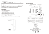
6.3 Board description
The board may appear dierent to that
illustrated.
Depending on the product version, the
board may not be equipped with all
functions.
BOARD DESCRIPTION
Connector Function
J1 Camera power supply (V
OUT)
J2 Heater power supply (V
OUT)
J3 Power supply for the board (V
IN)
J4 Auxiliary output (V
OUT)
J5 Power supply connector/jumper
J6 Fan power supply (V
OUT)
Tab. 1
1
Dierent alternatives are available depending on the
version. VOUT = 12Vdc o VOUT = 24Vac, in relation to the
type of power supply installed (7.2.1 Camera power
supply installation, page9). VOUT = VIN, only for housings
powered in 12Vdc or 24Vac, with jumper inserted (J5).
2
From 100Vac a 240Vac, 24Vac o12Vdc.
3
Same voltage applied to power supply terminal of the
board (J3).
4
To install a power supply in 12Vdc or 24Vac refer to the
relative chapter (7.2.1 Camera power supply installa-
tion, page9).
J1 J4 J2
J3J6 J5
Fig. 3
Nominal section of the cables used: from
0.2mm² up to 2.5mm².
6.4 Connection of the power
supply line
CAUTION! The type of cable used must be
compatible with the planned use. Comply
with the national regulations in force on
electrical installation.
Connect the safety earth to the relative
terminal of the power supply connector.
Earth cable should be about 10mm longer
than the other two, so that it will not be
disconnected accidentally if pulled.
Insert the cables inside the housing using the cable
glands. The cable glands are suitable for conductors
with diameters of between 5mm and 10mm. The
section of the cable inside the housing must be
suciently long to allow connection. Suitably lock
the cable glands.

EN - English - Instruction manual
8 MNVCHTG_1702_EN
6.5 Installation of the version
with double lter for air renewal
During installation pay attention to the
orientation of the air inlet lter ns.
OUT
Fig. 4
To guarantee weatherproof protection, install the
housing on the support following the inclination
limits as shown in the picture.
Depending on the angle of inclination of the housing,
the orientation of the lter ns must prevent water
penetrating in case of rain:
0˚
45°
45°
Fig. 5 Maximum tilt of the transversal axis: 0°.
Maximum tilt of the longitudinal axis: ±45°.
6.6 Desiccant bag
Take the dessicant salt bag out of its pack and insert it
into the product.
6.7 Replacement of the
germanium window
Unscrew the front window fastening screws using the
hexagonal wrench included in the supply. Remove
the window and position the replacement part,
making sure the seal remains in its seat. Replace the
housing and fasten in place using the previously
removed fastening screws.
Fig. 6

Instruction manual - English - EN
9MNVCHTG_1702_EN
7 Accessories
For further details on conguration and
use, refer to the relative manual.
7.1 Heater
7.1.1 Heater installation
At the end of istallation, connect the wiring to the
terminal (heater power supply, 6.3 Board description,
page7).
7.2 Camera power supply
7.2.1 Camera power supply installation
Not usable in housings with wiper device
installed.
Pay attention to the voltage used to power
the circuit. Depending on requirements use
the correct power supply kit.
Usable power supplies:
• IN from 100Vac up to 240Vac, 50/60Hz - OUT
12Vdc, 1.25A
• IN 230Vac, 50Hz - OUT 24Vac, 50Hz, 400mA
Fig. 7 Camera power supply.
After installation, connect the power supply to
the connector (power supply connector, 6.3 Board
description, page7).
8 Maintenance and cleaning
Before doing any technical work on the
device, disconnect the power supply.
8.1 Cleaning
8.1.1 Cleaning the window and plastic
parts
Avoid ethyl alcohol, solvents, hydrogenated
hydrocarbide, strong acid and alkali. Such
products may irreparably damage the
surface.
We recommend using a soft cloth with neutral soap
diluted with water or specic products to clean the
glasses lenses.
9 Disposal of waste
materials
This symbol mark and recycle system
are applied only to EU countries and not
applied to other countries of the world.
Your product is designed and manufactured with
high quality materials and components which can be
recycled and reused.
This symbol means that electrical and electronic
equipment, at their end-of-life, should be disposed of
separately from your household waste.
Please dispose of this equipment at your local
Community waste collection or Recycling centre.
In the European Union there are separate collection
systems for used electrical and electronic products.

EN - English - Instruction manual
10 MNVCHTG_1702_EN
10 Technical data
10.1 General
Die-cast aluminium back and front cover plates
Extruded aluminium body and external slide
Epoxypolyester powder painting, RAL9002 colour
Stainless steel external screws
10.2 Mechanical
Internal usable area (WxH): 134x88mm (5.1x3.5in)
Internal usable length (with or without accessories):
273mm (10.7in)
Cable glands: 3xM16
Unit weight: 4.1kg (9lb)
10.3 Housing's window
Germanium window
• Usable diameter: 55mm (2.1in)
• Thick: 2mm (0.07in)
• External treatment: scratch resistant (Hard Carbon
Coating - DLC), non-reective
• Internal treatment: non-reective
• Spectral range: from 7.5m up to 14m
• Medium transmittance (from 7.5m up to
11.5m): 90%
• Medium transmittance (from 11.5m up to 14m):
77%
10.4 Electrical
Supply voltage/Current consumption (version with
heater, Ton 15°C±3°C (59°F ±5°F), To 22°C±3°C
(72°F±5°F)):
• 12Vdc, 1.6A max
• 24Vac, 0.85A max, 50/60Hz
• 120Vac, 0.35A max, 50/60Hz
• 230Vac, 0.18A max, 50/60Hz
Camera power supply
• IN from 100Vac up to 240Vac, 50/60Hz - OUT
12Vdc, 1.25A
• IN 230Vac, 50Hz - OUT 24Vac, 50Hz, 400mA
10.5 Environment
For installation indoors and outdoors
Operating temperature with heating: from -20°C
(-4°F) up to +60°C (140°F)
10.6 Certications
Electrical safety (CE): EN60065
Electromagnetic compatibility (CE): EN50130-4,
EN61000-6-3
IP protection degree: EN60529 (IP66/IP67, with cable
glands)
EAC certication

Instruction manual - English - EN
11MNVCHTG_1702_EN
11 Technical drawings
The dimensions of the drawings are in millimetres.
153
175 42 32
134
Ø 102
141
168
88
A - A
A
B - B
A
B
B
Ø 55
Ø 72
273
365
493
C - C
C
C
USABLE
AREA
USABLE AREA
FRONT FLANGE
Fig. 8 HTG.

MNVCHTG_1702_EN
Headquarters Italy Videotec S.p.A.
Via Friuli, 6 - I-36015 Schio (VI) - Italy
Tel. +39 0445 697411 - Fax +39 0445 697414
Email: [email protected]
France Videotec France SARL
Immeuble Le Montreal, 19bis Avenue du Québec, ZA de Courtaboeuf
91140 Villebon sur Yvette - France
Tel. +33 1 60491816 - Fax +33 1 69284736
Email: info.fr@videotec.com
Asia Pacic Videotec (HK) Ltd
Flat 8, 19/F. On Dak Industrial Building, No. 2-6 Wah Sing Street
Kwai Chung, New Territories - Hong Kong
Tel. +852 2333 0601 - Fax +852 2311 0026
Email: info.hk@videotec.com
Americas Videotec Security, Inc.
Gateway Industrial Park, 35 Gateway Drive, Suite 100
Plattsburgh, NY 12901 - U.S.A.
Tel. +1 518 825 0020 - Fax +1 518 825 0022
Email: info.usa@videotec.com
www.videotec.com

MNVCHTG_1702_IT
Headquarters Italy Videotec S.p.A.
Via Friuli, 6 - I-36015 Schio (VI) - Italy
Tel. +39 0445 697411 - Fax +39 0445 697414
Email: [email protected]
France Videotec France SARL
Immeuble Le Montreal, 19bis Avenue du Québec, ZA de Courtaboeuf
91140 Villebon sur Yvette - France
Tel. +33 1 60491816 - Fax +33 1 69284736
Email: info.fr@videotec.com
Asia Pacic Videotec (HK) Ltd
Flat 8, 19/F. On Dak Industrial Building, No. 2-6 Wah Sing Street
Kwai Chung, New Territories - Hong Kong
Tel. +852 2333 0601 - Fax +852 2311 0026
Email: info.hk@videotec.com
Americas Videotec Security, Inc.
Gateway Industrial Park, 35 Gateway Drive, Suite 100
Plattsburgh, NY 12901 - U.S.A.
Tel. +1 518 825 0020 - Fax +1 518 825 0022
Email: info.usa@videotec.com
www.videotec.com

MNVCHTG_1702_FR
Headquarters Italy Videotec S.p.A.
Via Friuli, 6 - I-36015 Schio (VI) - Italy
Tel. +39 0445 697411 - Fax +39 0445 697414
Email: [email protected]
France Videotec France SARL
Immeuble Le Montreal, 19bis Avenue du Québec, ZA de Courtaboeuf
91140 Villebon sur Yvette - France
Tel. +33 1 60491816 - Fax +33 1 69284736
Email: info.fr@videotec.com
Asia Pacic Videotec (HK) Ltd
Flat 8, 19/F. On Dak Industrial Building, No. 2-6 Wah Sing Street
Kwai Chung, New Territories - Hong Kong
Tel. +852 2333 0601 - Fax +852 2311 0026
Email: info.hk@videotec.com
Americas Videotec Security, Inc.
Gateway Industrial Park, 35 Gateway Drive, Suite 100
Plattsburgh, NY 12901 - U.S.A.
Tel. +1 518 825 0020 - Fax +1 518 825 0022
Email: info.usa@videotec.com
www.videotec.com

MNVCHTG_1702_DE
Headquarters Italy Videotec S.p.A.
Via Friuli, 6 - I-36015 Schio (VI) - Italy
Tel. +39 0445 697411 - Fax +39 0445 697414
Email: [email protected]
France Videotec France SARL
Immeuble Le Montreal, 19bis Avenue du Québec, ZA de Courtaboeuf
91140 Villebon sur Yvette - France
Tel. +33 1 60491816 - Fax +33 1 69284736
Email: info.fr@videotec.com
Asia Pacic Videotec (HK) Ltd
Flat 8, 19/F. On Dak Industrial Building, No. 2-6 Wah Sing Street
Kwai Chung, New Territories - Hong Kong
Tel. +852 2333 0601 - Fax +852 2311 0026
Email: info.hk@videotec.com
Americas Videotec Security, Inc.
Gateway Industrial Park, 35 Gateway Drive, Suite 100
Plattsburgh, NY 12901 - U.S.A.
Tel. +1 518 825 0020 - Fax +1 518 825 0022
Email: info.usa@videotec.com
www.videotec.com

MNVCHTG_1702_RU
Headquarters Italy Videotec S.p.A.
Via Friuli, 6 - I-36015 Schio (VI) - Italy
Tel. +39 0445 697411 - Fax +39 0445 697414
Email: [email protected]
France Videotec France SARL
Immeuble Le Montreal, 19bis Avenue du Québec, ZA de Courtaboeuf
91140 Villebon sur Yvette - France
.: +33 1 60491816 - : +33 1 69284736
Email: info.fr@videotec.com
Азиатско-Тихоокеанский регион Videotec (HK) Ltd.
Flat 8, 19/F. On Dak Industrial Building, No. 2-6 Wah Sing Street
Kwai Chung, New Territories - Hong Kong
Tel. +852 2333 0601 - Fax +852 2311 0026
Email: info.hk@videotec.com
Americas Videotec Security, Inc.
Gateway Industrial Park, 35 Gateway Drive, Suite 100
Plattsburgh, NY 12901 - U.S.A.
Tel. +1 518 825 0020 - Fax +1 518 825 0022
Email: info.usa@videotec.com
www.videotec.com

MNVCHTG_1702
Headquarters Italy Videotec S.p.A.
Via Friuli, 6 - I-36015 Schio (VI) - Italy
Tel. +39 0445 697411 - Fax +39 0445 697414
Email: [email protected]
France Videotec France SARL
Immeuble Le Montreal, 19bis Avenue du Québec, ZA de Courtaboeuf
91140 Villebon sur Yvette - France
Tel. +33 1 60491816 - Fax +33 1 69284736
Email: info.fr@videotec.com
Asia Pacic Videotec (HK) Ltd
Flat 8, 19/F. On Dak Industrial Building, No. 2-6 Wah Sing Street
Kwai Chung, New Territories - Hong Kong
Tel. +852 2333 0601 - Fax +852 2311 0026
Email: info.hk@videotec.com
Americas Videotec Security, Inc.
Gateway Industrial Park, 35 Gateway Drive, Suite 100
Plattsburgh, NY 12901 - U.S.A.
Tel. +1 518 825 0020 - Fax +1 518 825 0022
Email: info.usa@videotec.com - www.videotec.com
www.videotec.com
/