Page is loading ...

1
DDX 102 Tx/Rx • Setup Guide
This guide provides basic instructions for an experienced installer to set up and operate the DDX 102 Tx/Rx.
NOTES:
• Refer to www.extron.com for the product specifications.
• The DDX 102 extenders are not compatible with any Extron fiber optic products.
• The DDX 102 extenders do not support transmission of HDCP content video signals.
Description
The Extron DDX 102 Tx/Rx are ber optic transmitter and receiver units that can extend Dual Link DVI signals using two
multimode ber cables.
The DDX 102 Tx/Rx units can extend Dual Link DVI video signals (2560x1600 @ 60 Hz) up to 1,640 feet (500 m) using two
mutimode ber optic cables. The units can also extend Single Link DVI signals (1920x1200 @ 60 Hz) up to the same maximum
distances as Dual Link DVI.
The transmitter plugs directly into the source device and the receiver plugs directly into the display device.
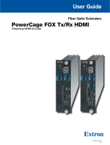
Front Panel and Side Panel Features
A
Power LED — The blue LED on the transmitter and receiver indicates the unit is
receiving power.
B
Status LED — The blue LED on the bottom provides the status of EDID learning
on the transmitter. The Status LED indicates power on the unit simultaneously
with the top Power LED. On the receiver, this is simply an additional power status
LED.
C
EDID Record button (transmitter only) — Iinitiates the EDID recording process.
D
Thumb screws — Two thumb screws, one on each side, fasten the device onto
the DVI connector of a product.
CLASS 1 LASER PRODUCT
5VDC 1 2
STATUS
A
A
A
B
B
B
C
C
C
D
D
D
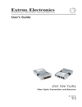
Top Panel Features
E
DVI-D Dual Link connector — The transmitter and receiver both have a DVI-D Dual Link connector.
Bottom Panel Features:
E
E
E
F
Power Input — The transmitter and receiver both have a DC jack for power input on the top left
corner of the bottom panel.
G
LC connectors — The transmitter and receiver both have two LC fiber optic connectors or
receptacles as interconnects for fiber optic cables.
NOTE: Only one fiber optic cable is needed for DVI Single Link video signals.
F
F
FG
G
G
Installation and Operation
NOTE: Perform EDID Learning operation first. After EDID is set up, follow the instructions for Connection.
CAUTION:
• This unit outputs continuous invisible light, which may be harmful to the eyes; use with caution. For additional safety,
plug the attached dust caps into the optical transceivers when the fiber cable is unplugged.
• L’appareil émet une lumière invisible en continu, à utiliser avec précaution. Pour une sécurité renforcée, associez les
bouchons anti-poussière à l’ensemble émetteur/récepteur optique lorsque le câble fibre optique est débranché.

2
DDX 102 Tx/Rx • Setup Guide (Continued)
EDID Learning
The transmitter features the ability of EDID emulation. It has the ability to record and store
EDID from the display. To do so, follow these steps:
1. Turn on the display device.
2. Connect the 5V power supply to the transmitter. The Power LED turns on.
CLASS 1 LASER PRODUCT
5VDC 1 2
STATUS
ATTENTION:
• Always use a power supply provided by or specified by Extron. Use of an unauthorized power supply voids all
regulatory compliance certification and may cause damage to the supply and the end product.
• Utilisez toujours une source d’alimentation fournie ou recommandée par Extron. L’utilisation d’une source
d’alimentation non autorisée annule toute certification de conformité réglementaire, et peut endommager la source
d’alimentation et l’unité.
• Unless otherwise stated, the AC/DC adapters are not suitable for use in air handling spaces or in wall cavities.
The power supply is to be located within the same vicinity as the Extron AV processing equipment in an ordinary
location, Pollution Degree 2, secured to the equipment rack within the dedicated closet, podium or desk.
• Sauf mention contraire, les adaptateurs CA/CC ne conviennent pas à une utilisation dans les espaces d’aération
ou dans les cavités murales. La source d’alimentation doit être placée à proximité de l’équipement de traitement
audiovisuel Extron dans un emplacement ordinaire soumis à un degré de pollution de catégorie II, solidement fixée
au rack d’équipement d’une baie technique, d’un pupitre, ou d’un bureau.
• The installation must always be in accordance with the applicable provisions of National Electrical Code
ANSI/NFPA 70, article 75 and the Canadian Electrical Code part 1, section 16. The power supply shall not be
permanently fixed to building structure or similar structure.
• L’installation doit toujours être conforme aux dispositions applicables du Code américain de l’électricité (National
Electrical Code) ANSI/NFPA 70, article 75, et du Code canadien de l’électricité, partie 1, section 16. La source
d’alimentation ne devra pas être fixée de façon permanente à la structure de bâtiment ou à d’autres structures
similaires.
NOTE: Apply power to the display device and the transmitter every time EDID is stored.
3. With the transmitter disconnected from the display device, press and release the recessed EDID Record button on the left
side of the transmitter with a paper clip or similar tool. The blue Status LED blinks twice and the LED stays on.
4. Connect the transmitter to the display device. The blue Status LED stays
lit for about 8 seconds indicating that the EDID recording is in process.
After EDID is recorded, the blue Status LED stops lighting and remains off.
NOTE: The transmitter must remain connected to the display
device and the power supply for the entire time that the EDID
capture is taking place.
5. Disconnect the transmitter from the display device and connect it to the
DVI output of the source device.
NOTE: If the source provides 5 VDC power via Pin 14 of the DVI
output, the transmiter can be powered without an external power
supply.
CLASS 1 LASER PRODUCT
5VDC 2 1
STATUS
Hi-resolution Displa
y
with DVI-D Input
DDX 102 Rx
CLASS 1 LASER PRODUCT
5VDC
1 2
STATUS
PC with DVI-D Output
DDX 102 Tx

3
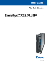
Connection
CLASS 1 LASER PRODUCT
5
V
DC
1 2
STATUS
CLA
SS 1
LAS
E
R PR
ODUC
T
5VDC 2
1
STATUS
Hi-resolution Display
with DVI-D Input
PC with DVI-D Output
Multi Mode Fiber
(2)
Up to 500 m
(1,640’)
DDX 102 Tx DDX 102 Rx
1. Ensure that the source device is off, connect the transmitter to the DVI output of the source, and tighten the thumbscrews.
2. Ensure that the display device is on, connect the receiver to the DVI input of the display, and tighten the thumbscrews.
3. Using two LC fiber optic cables, connect port 1 of the transmitter to port 1 of the receiver and connect port 2 to port 2 as
shown in the image below at the right.
NOTE: If Single Link DVI is used, only fiber line 1 needs to be connected.
4. Using two LC fiber optic cables, connect port 1 of the transmitter to port 1 of
the receiver and connect port 2 to port 2 as shown in the image at right.
NOTE: If Single Link DVI is used, only fiber ine 1 needs to be
connected.
5. Connect the 5V power adapters to the transmitter and the receiver. The
Power LEDs turn on.
NOTE: The power adapter does not need to be connected to the
transmitter if the graphic source provides enough power to operate
the transmitter.
6. Turn on the source device and ensure that the Status LEDs on the
transmitter and receiver are on.
CLASS 1 LASER PRODUCT
5VDC 1 2
STATUS
CLASS 1 LASER PRODUCT
5VDC 2 1
STATUS
Fiber Line 2
Fiber Line 1
Troubleshooting
The display does not show an image
• Ensure that all plugs and jacks used by external power supplies are firmly connected.
• Ensure that the Power and Status LEDs for both the transmitter and receiver are lit.
• Ensure that the DVI ports are firmly plugged into the computer and display.
• Ensure that the transmitter and receiver are plugged properly to the computer and display.
• Ensure that the fiber optic cables are connecting the correct ports. Port 1 of the transmitter must be connected to port 1 of
the receiver. Port 2 of the transmitter must be connected to port 2 of the receiver.
• Ensure that the source device and output device are powered on and have booted up correctly.
• Ensure that the correct EDID information has been stored on the transmitter. When using the DDX 102 Tx/Rx for the first
time or if the display device is changed, it is essential to set up the EDID Minder
™
as described in steps 1 through 5 of EDID
Learning on page2 of this guide.
• Reset the system by unplugging and reconnecting the DVI connectors or the power jacks.
• Reboot the computer.

4
68-2276-50 Rev. B
10 20
For information on safety guidelines, regulatory compliances, EMI/EMF compatibility, accessibility, and related topics, see the
Extron Safety and Regulatory Compliance Guide on the Extron website.
© 2012-2020 Extron — All rights reserved. www.extron.com
All trademarks mentioned are the property of their respective owners.
Worldwide Headquarters: Extron USA West, 1025 E. Ball Road, Anaheim, CA 92805, 800.633.9876
Screen is distorted or displays noise
• Ensure that the cable length does not exceed the specified cable lenghts for multimode or singlemode fiber optic extension.
• Ensure that the cables are high quality fiber optic cable and are terminated with securely fitting plugs.
• Ensure that the resolution is correctly set, using the EDID Minder (see Installation and Operation on page1).
• View the display properties of the source device to check the output resolution.
For Single Link, the resolution and refresh rate should not exceed 1920 x 1200 @ 60 Hz.
For Dual Link, the resolution and refresh rate should not exceed 2560 x 1600 @ 60 Hz.
• Reset the system by unplugging and reconnecting the DVI connectors or the power jacks.
/