Page is loading ...

User Guide
FOX T UWP 302
Fiber Optic Extender
Two Input Fiber Optic Transmitter - Decorator-style Wallplate
68-2092-01 Rev. D
01 19

Safety Instructions
Safety Instructions • English
WARNING: This symbol, , when used on the product, is intended to
alert the user of the presence of uninsulated dangerous voltage within
the product’s enclosure that may present a risk of electric shock.
ATTENTION: This symbol, , when used on the product, is intended
to alert the user of important operating and maintenance (servicing)
instructions in the literature provided with the equipment.
For information on safety guidelines, regulatory compliances, EMI/EMF
compatibility, accessibility, and related topics, see the Extron Safety and
Regulatory Compliance Guide, part number 68-290-01, on the Extron
website, www.extron.com.
Sicherheitsanweisungen • Deutsch
WARNUNG: Dieses Symbol auf dem Produkt soll den Benutzer
darauf aufmerksam machen, dass im Inneren des Gehäuses dieses
Produktes gefährliche Spannungen herrschen, die nicht isoliert sind und
die einen elektrischen Schlag verursachen können.
VORSICHT: Dieses Symbol auf dem Produkt soll dem Benutzer in
der im Lieferumfang enthaltenen Dokumentation besonders wichtige
Hinweise zur Bedienung und Wartung (Instandhaltung) geben.
Weitere Informationen über die Sicherheitsrichtlinien, Produkthandhabung,
EMI/EMF-Kompatibilität, Zugänglichkeit und verwandte Themen finden Sie in
den Extron-Richtlinien für Sicherheit und Handhabung (Artikelnummer
68-290-01) auf der Extron-Website, www.extron.com.
Instrucciones de seguridad • Español
ADVERTENCIA: Este símbolo, , cuando se utiliza en el producto,
avisa al usuario de la presencia de voltaje peligroso sin aislar dentro del
producto, lo que puede representar un riesgo de descarga eléctrica.
ATENCIÓN: Este símbolo, , cuando se utiliza en el producto, avisa
al usuario de la presencia de importantes instrucciones de uso y
mantenimiento recogidas en la documentación proporcionada con el
equipo.
Para obtener información sobre directrices de seguridad, cumplimiento
de normativas, compatibilidad electromagnética, accesibilidad y temas
relacionados, consulte la Guía de cumplimiento de normativas y seguridad
de Extron, referencia 68-290-01, en el sitio Web de Extron, www.extron.com.
Instructions de sécurité • Français
AVERTISSEMENT : Ce pictogramme, , lorsqu’il est utilisé sur le
produit, signale à l’utilisateur la présence à l’intérieur du boîtier du
produit d’une tension électrique dangereuse susceptible de provoquer
un choc électrique.
ATTENTION : Ce pictogramme, , lorsqu’il est utilisé sur le produit,
signale à l’utilisateur des instructions d’utilisation ou de maintenance
importantes qui se trouvent dans la documentation fournie avec le
matériel.
Pour en savoir plus sur les règles de sécurité, la conformité à la
réglementation, la compatibilité EMI/EMF, l’accessibilité, et autres sujets
connexes, lisez les informations de sécurité et de conformité Extron, réf.
68-290-01, sur le site Extron, www.extron.com.
Istruzioni di sicurezza • Italiano
AVVERTENZA: Il simbolo, , se usato sul prodotto, serve ad
avvertire l’utente della presenza di tensione non isolata pericolosa
all’interno del contenitore del prodotto che può costituire un rischio di
scosse elettriche.
ATTENTZIONE: Il simbolo, , se usato sul prodotto, serve ad
avvertire l’utente della presenza di importanti istruzioni di funzionamento
e manutenzione nella documentazione fornita con l’apparecchio.
Per informazioni su parametri di sicurezza, conformità alle normative,
compatibilità EMI/EMF, accessibilità e argomenti simili, fare riferimento
alla Guida alla conformità normativa e di sicurezza di Extron, cod. articolo
68-290-01, sul sito web di Extron, www.extron.com.
Instrukcje bezpieczeństwa • Polska
OSTRZEŻENIE: Ten symbol, , gdy używany na produkt, ma na celu
poinformować użytkownika o obecności izolowanego i niebezpiecznego
napięcia wewnątrz obudowy produktu, który może stanowić zagrożenie
porażenia prądem elektrycznym.
UWAGI: Ten symbol, , gdy używany na produkt, jest przeznaczony do
ostrzegania użytkownika ważne operacyjne oraz instrukcje konserwacji
(obsługi) w literaturze, wyposażone w sprzęt.
Informacji na temat wytycznych w sprawie bezpieczeństwa, regulacji
wzajemnej zgodności, zgodność EMI/EMF, dostępności i Tematy pokrewne,
zobacz Extron bezpieczeństwa i regulacyjnego zgodności przewodnik, część
numer 68-290-01, na stronie internetowej Extron, www.extron.com.
Инструкция по технике безопасности • Русский
ПРЕДУПРЕЖДЕНИЕ: Данный символ, , если указан
на продукте, предупреждает пользователя о наличии
неизолированного опасного напряжения внутри корпуса
продукта, которое может привести к поражению электрическим
током.
ВНИМАНИЕ: Данный символ, , если указан на продукте,
предупреждает пользователя о наличии важных инструкций
по эксплуатации и обслуживанию в руководстве,
прилагаемом к данному оборудованию.
Для получения информации о правилах техники безопасности,
соблюдении нормативных требований, электромагнитной
совместимости (ЭМП/ЭДС), возможности доступа и других
вопросах см. руководство по безопасности и соблюдению
нормативных требований Extron на сайте Extron: ,
www.extron.com, номер по каталогу - 68-290-01.
安全说明 • 简体中文
警告: 产品上的这个标志意在警告用户该产品机壳内有暴露的危险 电压,
有触电危险。
注意: 产品上的这个标志意在提示用户设备随附的用户手册中有
重要的操作和维护(维修)说明。
关于我们产品的安全指南、遵循的规范、EMI/EMF 的兼容性、无障碍
使用的特性等相关内容,敬请访问 Extron 网站 , www.extron.com,参见
Extron 安全规范指南,产品编号 68-290-01
。

안전 지침 • 한국어
경고: 이 기호 가 제품에 사용될 경우, 제품의 인클로저 내에 있는
접지되지 않은 위험한 전류로 인해 사용자가 감전될 위험이 있음을
경고합니다.
주의: 이 기호 가 제품에 사용될 경우, 장비와 함께 제공된 책자에 나와
있는 주요 운영 및 유지보수(정비) 지침을 경고합
니다.
안전 가이드라인, 규제 준수, EMI/EMF 호환성, 접근성, 그리고 관련 항목에
대한 자세한 내용은 Extron 웹 사이트(www.extron.com)의 Extron 안전 및
규제 준수 안내서, 68-290-01 조항을 참조하십시오.
安全記事 • 繁體中文
警告: 若產品上使用此符號,是為了提醒使用者,產品機殼內存在著
可能會導致觸電之風險的未絕緣危險電壓。
注意 若產品上使用此符號,是為了提醒使用者,設備隨附的用戶手冊中有
重要的操作和維護(維修)説明。
有關安全性指導方針、法規遵守、EMI/EMF 相容性、存取範圍和相關主題的詳細資
訊,請瀏覽 Extron 網站:www.extron.com,然後參閱《Extron 安全性與法規
遵守手冊》,準則編號 68-290-01。
安全上のご注意
• 日本語
警告: この記号 が製品上に表示されている場合は、筐体内に絶縁されて
いない高電圧が流れ、感電の危険があることを示しています。
注意:この記号 が製品上に表示されている場合は、本機の取扱説明書に
記載されている重要な操作と保守(整備)の指示についてユーザーの注意
を喚起するものです。
安全上のご注意、法規厳守、EMI/EMF適合性、その他の関連項目に
つ い て は 、エ ク スト ロ ン の ウェ ブ サ イト www.extron.com よ り 『 Extron Safety
and Regulatory Compliance Guide』 ( P/N 68-290-01) をご覧ください。
Copyright
© 2019 Extron Electronics. All rights reserved.
Trademarks
All trademarks mentioned in this guide are the properties of their respective owners.
The following registered trademarks(
®
), registered service marks(
SM
), and trademarks(
TM
) are the property of RGBSystems, Inc. or
ExtronElectronics (see the current list of trademarks on the Terms of Use page at www.extron.com):
Registered Trademarks
(
®
)
Extron, AVTrac, Cable Cubby, ControlScript, CrossPoint, DTP, eBUS, EDID Manager, EDID Minder, Flat Field, FlexOS, Global Configurator,
GlobalScripter, GlobalViewer, Hideaway, Inline, IPIntercom, IPLink, KeyMinder, LinkLicense, LockIt, MediaLink, MediaPort, NetPA,
PlenumVault, PoleVault, PowerCage, PURE3, Quantum, SoundField, SpeedMount, SpeedSwitch, SystemINTEGRATOR, TeamWork,
TouchLink, V-Lock, VersaTools, VN-Matrix, VoiceLift, WallVault, WindoWall, XTP, and XTPSystems
Registered Service Mark
(SM)
: S3 Service Support Solutions
Trademarks
(
™
)
AAP, AFL (Accu-RateFrameLock), ADSP(Advanced Digital Sync Processing), Auto-Image, CableCover, CDRS(ClassD Ripple
Suppression), DDSP(Digital Display Sync Processing), DMI (DynamicMotionInterpolation), DriverConfigurator, DSPConfigurator,
DSVP(Digital Sync Validation Processing), eLink, EQIP, EverLast, FastBite, FOX, FOXBOX, HyperLane, IP Intercom HelpDesk, MAAP,
MicroDigital, Opti-Torque, ProDSP, QS-FPC(QuickSwitch Front Panel Controller), Room Agent, Scope-Trigger, ShareLink, SIS,
SimpleInstructionSet, Skew-Free, SpeedNav, Triple-Action Switching, True4K, Vector™ 4K , WebShare, XTRA, ZipCaddy, and ZipClip

FCC Class A Notice
This equipment has been tested and found to comply with the limits for a Class A digital
device, pursuant to part15 of the FCC rules. The ClassA limits provide reasonable
protection against harmful interference when the equipment is operated in a commercial
environment. This equipment generates, uses, and can radiate radio frequency energy and,
if not installed and used in accordance with the instruction manual, may cause harmful
interference to radio communications. Operation of this equipment in a residential area is
likely to cause interference. This interference must be corrected at the expense of the user.
NOTE: For more information on safety guidelines, regulatory compliances, EMI/
EMF compatibility, accessibility, and related topics, see the “Extron Safety and
Regulatory Compliance Guide” on the Extron website.
Class 1 Laser Product
Any service to this product must be carried out by Extron Electronics and its qualified
service personnel.
CAUTION: Using controls, making adjustments, or performing procedures in a manner
other than what is specified herein may result in hazardous radiation exposure.
NOTE: For more information on safety guidelines, regulatory compliances,
EMI/EMF compatibility, accessibility, and related topics, see the “Extron Safety and
Regulatory Compliance Guide” on the Extron website.
Produit laser de classe1
Si ce produit a besoin d’un quelconque entretient, celui-ci doit être fait par
ExtronElectronics et son personnel qualifié.
ATTENTION : L’utilisation de commandes, la réalisation de réglages, ou l’exécution de
procédures de manière contraire aux dispositions établies dans le présent document,
présente un risque d’exposition dangereuse aux radiations.
Remarque : Pour plus d'informations sur les directives de sécurité, les conformités
de régulation, la compatibilité EMI/EMF, l'accessibilité, et les sujets en lien, consultez le
«Informations de sécurité et de conformité Extron» sur le site internet d'Extron.

Conventions Used in this Guide
Notifications
The following notifications are used in this guide:
WARNING: Potential risk of severe injury or death.
AVERTISSEMENT :
Risque potentiel de blessur
e grave ou de mort.
ATTENTION:
•
Risk of pr
operty damage.
•
Risque de dommages matériels.
NOTE: A note draws attention to important information.
TIP: A tip provides a suggestion to make working with the application easier.
Software Commands
Commands are written in the fonts shown here:
^AR Merge Scene,,0p1 scene 1,1 ^B 51 ^W^C.0
[01]
R
0004
00300
00400
00800
00600
[02]
35
[17] [03]
E X! *X1&* X2)* X2#* X2! CE}
NOTE: For commands and examples of computer or device responses used in this
guide, the character “0” is used for the number zero and “O” is the capital letter
“o.”
Computer responses and directory paths that do not have variables are written in the font
shown here:
Reply from 208.132.180.48: bytes=32 times=2ms TTL=32
C:\Program Files\Extron
Variables are written in slanted form as shown here:
ping xxx.xxx.xxx.xxx —t
SOH R Data STX Command ETB ETX
Selectable items, such as menu names, menu options, buttons, tabs, and field names are
written in the font shown here:
From the File menu, select New.
Click the OK button.
Specifications Availability
Product specifications are available on the Extron website, www.extron.com.
Extron Glossary of Terms
A glossary of terms is available at http://www.extron.com/technology/glossary.
aspx.
This Attention box is for
XTP and DTP ONLY,
delete for all others
Delete this entire NOTE if
the above ATTENTION IS
USED FOR XTP AND DTP
PRODUCTS. DELETE the
FIRST paragraph if NOT
TP. The second paragraph
is required if the Attention
is not used (it is duplicate
information).
Delete this entire section if
the product does not have
a battery.


viiFOX T UWP 302 Wallplate Transmitter • Contents
Contents
Introduction............................................................ 1
About this Guide ................................................. 1
About the FOX T UWP 302 ................................. 1
System Compatibility ...................................... 2
Cable Transmission Modes ............................. 3
Key Features ...................................................... 3
Installation and Operation .................................. 5
Installation Overview ........................................... 5
Rear Panel Features ........................................... 6
Front Panel Features ........................................... 8
Outside-the-Faceplate Features ...................... 8
Inside-the-Faceplate Features ......................... 9
Mounting and Making Connections .................. 10
Mounting ...................................................... 10
Connecting the HDMI Connector .................. 11
Wiring for Remote RS-232 and Alarm
Communication ........................................... 11
Wiring the Power Supply .............................. 12
Operation ......................................................... 13
Initial Power Up............................................. 13
System Reset ............................................... 14
SIS Configuration and Control ........................ 15
Simple Instruction Set Control .......................... 15
SIS Programming Guide ............................... 15
Using the Command and Response Tables
for SIS Commands ...................................... 16
Symbol Definitions ........................................ 16
Command and Response Tables for SIS
Commands ..................................................... 18
Input Switching Commands .......................... 18
Audio Configuration Commands ................... 18
Picture Adjustment Commands
(Analog Only) ............................................... 19
EDID Commands .......................................... 19
Advanced Configuration Commands ............ 20
FOX Extenders Control Program .................... 23
Installing the Software ....................................... 23
Starting the Software ........................................ 24
Using the Software ........................................... 24
Menu Bar ..................................................... 25
Main Screen ................................................. 32
Reference Information ...................................... 41
Firmware Loader .............................................. 41
Downloading Extron Firmware Loader .......... 41
Installing FIrmware Loader ............................ 42
Firmware Updates ............................................ 43
Downloading Firmware ................................. 43
Installing Firmware with Firmware Loader ...... 44

FOX T UWP 302 Wallplate Transmitter • Contents viii

FOX T UWP 302 Wallplate Transmitter • Introduction 1
Introduction
This section contains general information about this guide, the FOX T UWP 302 Universal
Wallplate Transmitter, and selected device features. Topics in this section include:
• About this Guide
• About the FOX T UWP 302
• Key Features
About this Guide
This guide describes installation, operation, and control procedures, and reference
information for the FOX T UWP 302 Universal Wallplate Transmitter. In this guide,
“FOX T UWP 302” refers to the FOX T UWP 302 Universal Wallplate Transmitter in
singlemode or multimode.
About the FOX T UWP 302
The Extron FOX T UWP 302 is a three-gang universal wallplate transmitter with a two input
integrated switcher that provides long haul transmission of HDCP-compliant HDMI, RGBHV,
or HD component video; stereo audio; and RS-232 signals over fiber optic cabling. It
delivers pixel-for-pixel transmission of images up to 1920x1200 and 2K, including HDTV
1080p @ 60 Hz.
To configure and control the FOX T UWP 302, connect a host device, such as a computer,
and enter Simple Instruction Set (SIS) commands (see SIS Configuration and Control
on page 15) or use the FOX Extenders Control Program (see FOX Extenders Control
Program on page 23).
WARNING: Potential risk of severe injury. The FOX T UWP 302 outputs continuous
invisible light, which may be harmful to the eyes; use with caution.
AVERTISSEMENT: Risque potentiel de blessure grave ou de mort. Le
FOX T UWP 302 émet une lumière invisible en continu qui peut être dangereux pour
les yeux, à utiliser avec précaution.
• Do not look into the rear panel fiber optic cable connectors or into the fiber optic
cables themselves.
•
Ne r
egardez pas dans les connecteurs de câble fibre optique sur le panneau arrière
ou dans les câbles fibre optique eux-mêmes.
•
Plug the attached dust caps into the optical transceivers when the fiber cable is
unplugged.
•
Branchez les protections contre la poussière dans l’ensemble émetteur/récepteur
lorsque le câble fibre optique est débranché.

FOX T UWP 302 Wallplate Transmitter • Introduction 2
12V
1.0A MAX
FOX SR HDMI
POWER
LINK
LINK
OPTICAL
RxTx
HDMI AUDIO
HDMI
AUDIO
OUTPUTS
ON
OFF
REMOTE
RS-232
Tx Rx
RS-232
OVER FIBER
ALARM
Tx Rx
1 2
L
R
POWER
PC
HDMI
HDCP
AUD
IO INPUT
HDMI INPUT
COMPUTE
R INP
UT
AUDIO
STANDBY
CLASS 2 WIRING
1
2
XPA 1002
LEVEL
1
1
2
1
2
LIMITER/
PROTECT
SIGNAL
2
INPUTS
OUTPUT
REMOTE
0
0
VOL/MUTE
10V 50 mA
100-240V 1.3A, 50-60Hz
Extron
XPA 1002
Power
Amplier
Extron
SI 28
Surface-
mount
Speakers
Extron
FOX T UWP 302
Fiber Optic
Transmitter
Laptop
with HDMI
Output
Flat Panel
Display
HDMI + Audio
HDMI
Up to 30 km (18.75 miles)
Singlemode Fiber
SM Model
Audio
Audio
VGA
Laptop
with VGA
Output
Ext
ron
FO
XBOX SR HDMI
Fi
ber Optic Receiver
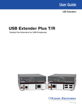
Figure 1. Typical FOX T UWP 302 Application
System Compatibility
The FOX T UWP 302 supports Plus or Non-Plus mode transmission for compatibility with
FOX receivers. Devices in Plus mode are only compatible with other devices in Plus mode.
Use SIS commands (see Plus mode transmission on page 20) or the FOX Extenders
Control Program (see Plus Mode Transmission panel on page 36) to change the mode.
• Non-Plus — Supports resolutions from 640x480 up to 1600x1200 @ 60 Hz, including
480p up to 1080p @ 60 Hz. Embedded audio is not supported, but analog audio is
supported and HDCP compliant.
• Plus — Supports all resolutions supported in non-plus mode, plus 1920x1200 and
2K (2048x1080) @ 60 Hz. Embedded audio and analog audio are supported and are
both HDCP compliant.
Supported Receivers
Plus Mode Non-Plus Mode
FOXBOX Rx DVI Plus FOX II R DP FOXBOX Rx VGA
FOXBOX Rx HDMI FOX II R DP 4K FOXBOX Rx DVI
FOXBOX SR HDMI PowerCage 401 DR HD FOX 500 DVI Rx
PowerCage FOX Rx DVI Plus FOX 500 Rx
PowerCage FOX Rx HDMI PowerCage FOX Rx VGA
PowerCage FOX SR HDMI PowerCage FOX Rx DVI

FOX T UWP 302 Wallplate Transmitter • Introduction 3
Cable Transmission Modes
The transmitter is categorized by the type of fiber optic cable, multimode
(FOX T UWP 302 MM) or singlemode (FOX T UWP 302 SM), which define the effective
range of transmission:
• Multimode — Long distance, up to 2 km (6,560 feet) (depending on the fiber cable)
• Singlemode — Very long distance, up to 30 km (18.75 miles)
Key Features
High reliability and maximum performance transmission over long distance fiber
optic cabling — Transmits HDMI or analog video and stereo audio signals over very long
distances using fiber optic cabling.
Inputs — Include a female HDMI type A connector; 15-pin HD connector for RGBHV,
RGBS, or HD component video; and a 3.5 mm stereo mini-jack for unbalanced stereo
audio.
All digital technology — Delivers pixel-for-pixel transmission of video signals to ensure
optimal image quality at resolutions up to 1920x1200 and 2K, including HDTV 1080p
@ 60 Hz.
Digital conversion of analog video — Analog signals are digitized, ensuring that a
reliable, high quality digital video signal is sent to the output destination.
Auto-input switching — Automatically switches to the lowest or highest priority input with
an active video signal for simplified operation.
HDCP-compliance
Key Minder — Authenticates and maintains continuous HDCP encryption between input
and output devices to ensure quick and reliable switching in professional AV environments,
while enabling simultaneous distribution of a single source signal to one or more displays.
EDID Minder — Automatically manages EDID communication between connected devices
to ensure that all sources properly power up and reliably display content.
Audio embedding — Converts analog stereo audio signals to digital HDMI audio when the
analog input is selected.
Audio gain and attenuation adjustment capability
LED indicators for signal presence, HDCP, and power — Provides a visual indication of
system status for real-time feedback and monitoring of key performance parameters.
Multimode and singlemode availability — Available as an 850 nm multimode model for
long-range transmissions up to 2 km (6,560 feet), and a 1310 nm singlemode model for
extreme distances up to 30 km (18.75 miles).
Industry standard LC connectors — Provide reliable physical connectivity and precise
fiber core alignment.
Compatibility with the following Extron FOX series products:
•
Matrix switchers
— Creates HDCP-compliant signal distribution systems up to
1000x1000 and larger.
•
DisplayPort, HDMI, DVI Plus, DVI, and VGA receivers — Compatible with FOX
series DisplayPort, HDMI, and DVI Plus receivers up to 1920x1200 and 2K, including
HDTV 1080p/60. Compatible with FOX series DVI and VGA receivers up to 1600x1200,
including HDTV 1080p/60.
NOTE: The FOX T UWP 302 is not compatible with the FOX 3G HD-SDI, FOX 3G DVC,
or FOX AV models.

FOX T UWP 302 Wallplate Transmitter • Introduction 4
Front panel USB configuration port
Mounts in an included three-gang decorator-style wallplate — Includes a black or
white three-gang decorator-style wallplate to blend with a wide range of environments.
Includes LockIt HDMI cable lacing bracket
Energy-efficient external universal power supply included — Provides worldwide
compatibility, low power consumption, and reduced operating costs.

FOX T UWP 302 Wallplate Transmitter • Installation and Operation 5
Installation and
Operation
This section describes procedures to cable, connect, and manually operate the
FOX T UWP 302. Topics in this section include:
• Installation Overview
• Rear Panel Features
• Front Panel Features
•
Mounting and Making Connections
•
Operation
Installation Overview
Install the FOX T UWP 302 into an electrical UL Listed junction box.
CAUTION: Risk of personal injury. Failure to check the items listed below may result
in personal injury.
ATTENTION :
Risque de blessur
e. La non-vérification des éléments listés ci-dessous
peut provoquer des blessures.
ATTENTION: Failure to check the items listed below may result in property damage.
ATTENTION :
La non-vérification des éléments listés ci-dessous peut pr
ovoquer des
dommages matériels.
1.
Pr
epare the mounting surface
• Ensure there are no utility cables or pipes at the intended location that might be
damaged or cause injury when installing the device.
• Check that the installation meets building, electrical, and safety codes.
• Ensure there is sufficient space behind the device.
• Choose a location that will allow cable runs without interference.
NOTES:
• Cables may need to be installed in the wall or conduits before installation.
• For junction boxes, refer to the manufacturer for more installation
requirements.
2. Cut a hole in the mounting surface.
3. Install the junction box according to the junction box installation instructions.
4. Prepare and pull the cables through the junction box.
TIP: Secure cables with clamps or ties to provide strain relief.

FOX T UWP 302 Wallplate Transmitter • Installation and Operation 6
5. Trim back and insulate shields with heat shrink.
ATTENTION:
•
T
o prevent short circuits, the outer foil shield can be cut back to the point
where the cable exits the cable clamp. Both braided and foil shields should be
connected to an equipment ground at the other end of the cable.
•
Afin d’éviter les court cir
cuits, le blindage en aluminium extérieur peut être
réduit jusqu’à ce que le câble sorte de la cosse de câble. Le blindage tressé et
le blindage en aluminium devraient être connectés à la masse d’un équipement
à l’autre bout du câble.
6.
Connect cables to the r
ear panel connectors (see Rear Panel Features on page 6).
7.
Mount the FOX T UWP 302 enclosur
e into the junction box (see Mounting on page 10).
8.
Configur
e the FOX T UWP 302 with SIS commands (see SIS Configuration and
Control on page 15) or the FOX Extenders control program (see FOX Extenders
Control Program on page 23).
9.
Install the faceplate (see
Mounting on page 10).
Rear Panel Features
Tx
Rx
Rx
Tx
1
2
G
+
REMOTE
RS-232
ALARM
POWER
12V
0.6A MAX
-
RearRight Side
A
B
C
A
Fiber connector (see page 7)
B
Remote RS-232 and Alarm connector (see page 7)
C
Power connector (see page 7)
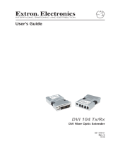
Figure 2. FOX T UWP 302 Rear Connectors from the Side and Rear Panels

FOX T UWP 302 Wallplate Transmitter • Installation and Operation 7
A
Fiber connector — For one-way video, audio, and serial communication from the
FOX T UWP 302 to a receiver, connect a fiber optic cable between the Tx port on the
FOX T UWP 302 and the Rx port on a compatible receiver.
To return serial data from a receiver to the FOX T UWP 302 (such as responses from a
controlled device) or for HDCP-compliance, connect a fiber optic cable between the Rx
port on the transmitter and the Tx port on the receiver.
WARNING: Potential risk of severe injury. The
FOX T UWP 302 outputs continuous invisible light, which may
be harmful to the eyes; use with caution.
AVERTISSEMENT: Risque potentiel de blessure grave ou
de mort. Le FOX T UWP 302 émet une lumière invisible en
continu qui peut être dangereux pour les yeux, à utiliser avec
précaution.
•
Do not look into the r
ear panel fiber optic cable connectors
or into the fiber optic cables themselves.
•
Ne r
egardez pas dans les connecteurs de câble fibre
optique sur le panneau arrière ou dans les câbles fibre
optique eux-mêmes.
•
Plug the attached dust caps into the optical transceivers
when the fiber cable is unplugged.
•
Branchez les pr
otections contre la poussière dans
l’ensemble émetteur/récepteur lorsque le câble fibre optique
est débranché.
NOTES:
• Ensure that you use the proper fiber optic cable. Typically, singlemode fiber
optic cable has a yellow jacket and multimode fiber optic cable has an orange
or aqua jacket.
•
Only one fiber optic cable, transmitter
-Tx-to-receiver-Rx, is required for video,
audio, and serial command transmission, but the HDMI signal output on the
receiver will not be HDCP-compliant and the FOX T UWP 302 will not receive
RS-232 reports from the controlled device.
B
Remote RS-232 port — For serial RS-232 control, connect a host device
to the transmitter via the leftmost poles (Tx, Rx, and G) of this 5-pole
captive screw connector (see Wiring for Remote RS-232 and Alarm
Communication on page 11 for wiring configuration).
Alarm output port — For remote monitoring of the status of fiber optic
link 2, connect a custom or furnished monitoring device to the transmitter
via the rightmost poles (1 and 2) of this 5-pole captive screw connector (see
Wiring for Remote RS-232 and Alarm Communication on page 11).
NOTE: Pins 1 and 2 short when link 2 does not detect any connection.
C
Power connector — Connect the provided external 12 VDC power supply
to this 3.5 mm, 2-pole captive screw connector (see Wiring the Power
Supply on page 12).
ALARM
Tx Rx 1 2
RS-232
OVER FIBER
RS-232
O
VER FIBER
Tx Rx
12V
1.0A MAX
POWER
Transmitter
to
Receiver
OPTICAL
Rx
Tx
LINK
LINK
OPTICAL
Rx
Tx

FOX T UWP 302 Wallplate Transmitter • Installation and Operation 8
Front Panel Features
Outside-the-Faceplate Features
POWER
PC
HDMI
HDCP
AUDIO INPUT
HDMI INPUT
COMPUTER INPUT
AUDIO
B
C
D
A
Figure 3. FOX T UWP 302 Outside-the-Faceplate Features
A
LED indicators
Power LED — Lights when the device receives 12 V from an external power supply.
PC LED — Lights when a computer input is detected.
HDMI LED — Lights when an HDMI input is detected.
HDCP LED — Lights if the HDMI input signal is HDCP encrypted.
Audio LED — Lights in one of the following ways when the transmitter detects audio
on the selected input:
• Lights when an analog audio signal remains above -44 dBV but turns off after the
audio signal level drops below the threshold continuously for 10 seconds.
• Lights when the transmitter detects digital embedded audio.
B
Audio Input connector — Connect an audio source to the 3.5 mm tip-ring-sleeve
(TRS) connector.
Tip (+)
Sleeve ( )
Sleeve ( )
Ring (
-
)
Tip (+)
Audio Plugs.eps
RCA Connector
3.5 mm Stereo Plug Connector
(balanced)
Sleeve ( )
Ring (R)
Tip (L)
3.5 mm Stereo Plug Connector
(unbalanced)
Figure 4. Wiring for Unbalanced Stereo Audio
C
Computer Input connector — Connect a video source to the female 15-pin HD
connector.
D
HDMI input connector — Connect a source device to the HDMI connector. This
connector can accept HDMI, DVI, or dual mode DisplayPort video signals.

FOX T UWP 302 Wallplate Transmitter • Installation and Operation 9
Inside-the-Faceplate Features
LINK 1
LINK 2
HDMI INPUT
AUDIO INPUT
COMPUTER INPUT
POWER
RESET
CONFIG
PC
HDMI
HDCP
AUDIO
A
B
C
Figure 5. FOX T UWP 302 Under-the-Faceplate Features
A
Link 1 and Link 2 LED indicators — Light when there is light present on the
corresponding fiber optic port.
B
Reset button — Press the Reset button to return device settings or firmware to the
factory default settings (see System Reset on page 14).
C
Config port — Connect a host device, such as a PC, to the USB mini-B configuration
port for RS-232 protocol control of all FOX T UWP 302 functions. Configure the
FOX T UWP 302 with SIS commands (see SIS Configuration and Control on
page 15) or the FOX Extenders control program (see FOX Extenders Control
Program on page 23).

FOX T UWP 302 Wallplate Transmitter • Installation and Operation 10
Mounting and Making Connections
Mounting
Before mounting an electrical UL Listed junction box, consider the mounting location and
prepare the surface as necessary.
Flush with
Wall Surface
Screws or Nails
Wall Stud
Junction Box
Mounting
Scr
ews
(6 Plcs)
Extron
FOX T UWP 302
Universal Wallplate
Transmitter
1
2
3
Figure 6. Mounting the FOX T UWP 302 Into a Junction Box
1. Mount the junction box in the wall or floor, following the directions provided with the
box.
2. Run the cables through the junction box (see figure 6,
1
).
ATTENTION:
• To prevent short circuits, the outer foil shield can be cut back to the point
where the cable exits the cable clamp. Both braided and foil shields should be
connected to an equipment ground at the other end of the cable.
• Afin d’éviter les court circuits, le blindage en aluminium extérieur peut être
réduit jusqu’à ce que le câble sorte de la cosse de câble. Le blindage tressé et
le blindage en aluminium devraient être connectés à la masse d’un équipement
à l’autre bout du câble.
TIP: Secure cables with clamps or ties to provide strain relief.
3. Disconnect power from all devices at the source.

FOX T UWP 302 Wallplate Transmitter • Installation and Operation 11
4. Connect all cables to the FOX T UWP 302 rear panel connectors.
5. Secure the FOX T UWP 302 enclosure to the box using three of the provided screws
into the slots at the top and bottom of the device (see figure 6,
2
on the previous
page).
6. Fasten the decorator-style wallplate onto the enclosure using six of the provided screws
in the holes at the top and bottom (see figure 6,
3
).
Connecting the HDMI Connector
Use an Extron LockIt lacing bracket to secure an HDMI cable to each device.
1. Plug the HDMI cables into the panel connection
(see
1
of the image to the right).
2. Loosen the side HDMI connection mounting screw from
the panel enough to allow the LockIt lacing bracket to
be placed over it (
2
). The screw does not have to be
removed.
3.
Place the LockIt lacing bracket on the scr
ew and against
the HDMI connector, then tighten the screw to secure
the bracket (
3
).
ATTENTION: Do not overtighten the HDMI
connector mounting screw. The shield to which it is
fastened is very thin and can easily be stripped.
ATTENTION : Ne serrez pas trop la vis de montage
du connecteur HDMI. Le blindage auquel elle
est attachée est très fin et peut facilement être
dénudé.
4. Loosely place the included tie wrap around the HDMI connector and the LockIt lacing
bracket (
4
).
5. While holding the connector securely against the lacing bracket, use pliers or a similar
tool to tighten the tie wrap, then remove any excess length.
Wiring for Remote RS-232 and Alarm Communication
The Remote RS-232 and Alarm connector is for RS-232 control (such as updating firmware,
status queries, and various control functions) and the alarm feature. Wire the connector as
shown in figure 7 below.
RxTx
Alarm Device
RS-232 Device
G
REMOTE
RS-232 ALARM
Tx Rx G1 2
12
Figure 7. Wiring the Remote RS-232 and Alarm Connector
1
2
3
4

FOX T UWP 302 Wallplate Transmitter • Installation and Operation 12
ATTENTION:
•
The length of exposed wir
es in the stripping process is critical. The ideal length is
3/16 inch (5 mm).
• La longueur des câbles exposés est primordiale lorsque l’on entreprend de les
dénuder. La longueur idéale est de 5mm (3/16inches).
• Any longer and the exposed wires may touch, causing a short circuit between
them.
•
S’ils sont un peu plus longs, les câbles exposés pourraient se toucher et pr
ovoquer
un court circuit.
• Any shorter and the wires can be easily pulled out even if tightly fastened by the
captive screws.
•
S’ils sont un peu plus courts, ils pourraient sortir
, même s’ils sont attachés par les
vis captives.
For RS-232 over fiber connection, cross the Tx and Rx lines once between the source and
the target.
The alarm pins do not produce any discrete on or off or voltage signals. It is an internal relay
to connect or disconnect a custom alarm circuit.
NOTE: If power is lost or if link 2 optical light is disconnected, lost, or broken, alarm
pins 1 and 2 internally short.
Wiring the Power Supply
Connect 12 VDC power supply to the 3.5 mm, 2-pole captive screw connector.
SECTION A–A
AA
Power Supply
Output Cord
2-Pole Captive Screw
Connector
Ridges
Smooth
Tie
Wrap
3/16”
(5 mm) Max.
Figure 8. Power Connector Wiring
CAUTION: Electric shock hazard. The wires must be kept separate while the power
supply is plugged in. Remove power before wiring.
ATTENTION: Risque de choc électrique: Les deux cordons d’alimentation doivent
être tenus à l’écart l’un de l’autre quand l’alimentation est branchée. Couper
l’alimentation avant de faire l’installation électrique.
/