Holtek Bestcomm RFs BCE-GENTrxN-00z User guide
- Type
- User guide
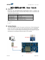
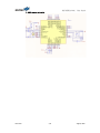
Holtek Bestcomm RFs BCE-GENTrxN-00z allows users to evaluate and develop wireless products via its three types of development boards: BCE-GENTrx0-00z without MCU, BCE-GENTRX8-00z with HT8 MCU (8-bit), and BCE-GENTRX32-00z with HT32 MCU (32-bit). It features a system architecture with ht66f2370 as the main control chip, programmable and supported by e-Link (8-bit MCU) development tools.
Holtek Bestcomm RFs BCE-GENTrxN-00z allows users to evaluate and develop wireless products via its three types of development boards: BCE-GENTrx0-00z without MCU, BCE-GENTRX8-00z with HT8 MCU (8-bit), and BCE-GENTRX32-00z with HT32 MCU (32-bit). It features a system architecture with ht66f2370 as the main control chip, programmable and supported by e-Link (8-bit MCU) development tools.


-
 1
1
-
 2
2
-
 3
3
-
 4
4
-
 5
5


Holtek Bestcomm RFs BCE-GENTrxN-00z User guide
- Type
- User guide
Holtek Bestcomm RFs BCE-GENTrxN-00z allows users to evaluate and develop wireless products via its three types of development boards: BCE-GENTrx0-00z without MCU, BCE-GENTRX8-00z with HT8 MCU (8-bit), and BCE-GENTRX32-00z with HT32 MCU (32-bit). It features a system architecture with ht66f2370 as the main control chip, programmable and supported by e-Link (8-bit MCU) development tools.
Ask a question and I''ll find the answer in the document
Finding information in a document is now easier with AI
Related papers
Other documents
-
Renesas H8S/2378F User manual
-
Trinamic TMCM-0930-TMCL Owner's manual
-
Panasonic MN103001G/F01K User manual
-
TRINAMIC / ANALOG DEVICES TMC4671+TMC6100-TOSV-REF Operating instructions
-
-
 YORKVILLE Audiopro 3400 User manual
-
-
NXP MWCT101xS Reference guide
-
 onsemi RSL10-002GEVB Operating instructions
-
Microchip Technology BM71-XPro User manual

