
IS4100 ScanQuest
®
Series
Laser Scan Engine
Installation and User’s Guide

Disclaimer
Honeywell International Inc. (“HII”) reserves the right to make changes in
specifications and other information contained in this document without prior notice,
and the reader should in all cases consult HII to determine whether any such
changes have been made. The information in this publication does not represent a
commitment on the part of HII.
HII shall not be liable for technical or editorial errors or omissions contained herein:
nor for incidental or consequential damages resulting from the furnishing,
performance, or use of this manual.
This document contains propriety information that is protected by copyright. All
rights reserved. No part of this document may be photocopied, reproduced, or
translated into another language without the prior written consent of HII.
© 1998 - 2010 Honeywell International Inc. All rights reserved.
Web Address: www.honeywellaidc.com
Trademarks
Metrologic is a registered trademark of Metrologic Instruments, Inc. or Honeywell
International Inc.
Other product names mentioned in this manual may be trademarks or registered
trademarks of their respective companies and are the property of their respective
owners.

TABLE OF CONTENTS
Introduction
Theory of Operation...............................................................................1
Accessories ...........................................................................................2
Components of the ScanQuest Engine .................................................3
Label Locations .....................................................................................4
Maintenance ..........................................................................................4
Automatic Scan Activation ........................................................................5
Applications and Protocols........................................................................5
Design Specifications
Operational ............................................................................................6
Maintenance ..........................................................................................6
Mechanical ............................................................................................7
Electrical ................................................................................................7
Environmental........................................................................................8
Compliance............................................................................................8
IS4125 Depth of Field ...............................................................................9
IS4125 Object Detection .........................................................................10
Design Specifications
Specifications for the Supplemental Window ......................................11
Default Settings
IS4125 Communication Parameters ...................................................12
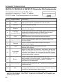
Scanner Terminations
IS4125-47 Connector Pin Assignments ..............................................18
IS4125-38 Connector Pin Assignments ..............................................19
IS4125-41, IS4125-63 & IS4125-76 Connector Pin Assignments ......20
IS4125-163 Connector Pin Assignments ............................................21
IS4110 Connector Pin Assignments....................................................22
iii

iv
TABLE OF CONTENTS
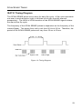
Scan Sense Timing
IS4110 Timing Diagram.......................................................................23
Regulatory Requirements and Warnings
Regulatory Requirements....................................................................24
Europe .................................................................................................25
United States .......................................................................................26
Canada ................................................................................................27
Warnings..............................................................................................27
Limited Warranty .....................................................................................28
Patents ....................................................................................................29
Index........................................................................................................30
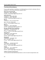
Customer Support ...................................................................................32
Technical Assistance...........................................................................32
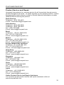
Product Service and Repair.................................................................33

1
INTRODUCTION
Honeywell’s IS4125 ScanQuest
®
Engines are compact laser bar code scanners
designed to be integrated with OEM devices. The ScanQuest series provides
fast, accurate, reliable scanning in a compact, lightweight package.
The IS4125 has built-in decoding for versatile OEM operations. The IS4125 has
flash upgradeable firmware. The IS4110 non-decode engine is also available to
be integrated with decode equipped OEM devices.
Note: The manufacturer of the end equipment must register with agencies
such as the Food and Drug Administration (FDA). The specifications
required for registration are not obtainable until the OEM manufacturer
uses the ScanQuest Engine in its final configuration. Therefore, it
becomes the responsibility of the manufacturer who incorporates the
scan engine into their product to comply with all federal laser safety
regulations. The manufacturer must submit a Laser Product Report for
the FDA in the US or similar forms as required by other countries.
Honeywell will assist its customers in complying with the necessary
procedures.
Theory of Operation
An object detection device is located behind the scanner window initiates the
scanning process. The detection device is active as long as the unit is being
powered. When the laser decodes a bar code, the scan engine transmits the
data to the host system.
If the same bar code stays in the field after successfully scanning, the laser stays
on for approximately four seconds and then turns off. This prevents unintentional
reads of the same bar code. To read the same symbol more than once, remove
the object from the scan field for approximately one second and then present the
symbol again.
If the bar code and object is removed from the field during the scanning process,
the laser turns off. In this stage, the scan engine’s computer remains on
“standby”.
However, if the object stays in the field, the laser remains on for up to
2.5 seconds trying to detect the bar code. To reactivate the scanning sequence,
remove the object.
The RS232 interface unit can be activated to scan by a command from the host.
When the unit is configured this way, the object detection is disabled
automatically.

2
INTRODUCTION
Accessories
The following are available:
IS4125 Decoded Scan Engine Part Numbers
PN DESCRIPTION MANUFACTURE/PART NO.
19-07092 Flex Ribbon 12 Pos x 70mm Burndy BFC12X70A4
M-07102 Thru Hole 12 Pos ZIF Connector Burndy FLWSLW125-1C7
M-07103 Flex Ribbon 12 Pos x 130mm Burndy BFC12X30A4
IS4110 Non-Decoded Scan Engine Part Numbers
PN DESCRIPTION MANUFACTURE/PART NO.
M-07104 Flex Ribbon 10 POS x 130mm Burndy BFC10X130A4

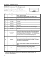
INTRODUCTION
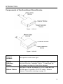
Components of the ScanQuest Scan Engine
Figure 1: IS4110
Figure 2: IS4125
Scanner
window:
This aperture emits laser light.
Object
Detection
Device:
When a specified time has elapsed without any scanning,
the unit will enter a “standby” mode. To reactivate the
unit, present an object in front of the window.
Ribbon Cables:
This IS4110 has a 10-position FFC/FPC cable and the
IS4125 has a 12-position FFC/FPC cable. Refer to
Scanner Termination starting on page 18.
3

INTRODUCTION
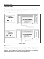
Label Locations
The serial number label is located on the bottom of the unit. On the top of the
unit is the “avoid exposure” and model number label.
The following are examples of these labels:
Figure 3: Labels
Maintenance
Smudges and dirt on the unit’s window can interfere with the unit’s performance.
If the window requires cleaning, use only a mild glass cleaner containing no
ammonia. When cleaning the window, spray the cleaner onto a lint free, non-
abrasive cleaning cloth then gently wipe the window clean.
4

5
AUTOMATIC SCAN ACTIVATION
An object detection device is located behind the scanner window initiates the
scanning process. In short range mode the signal projects approximately
101.61 mm – 177.84 mm (4" – 7") beyond the output window. In long range
mode the signal projects approximately 228.61 mm – 330.21 mm (9" – 13")
beyond the output window. The object detection device remains active as long
as the unit is powered.
When the unit remains dormant for a time, the laser will turn off. In this stage, the
scan engine’s computer is on “standby”. To reactivate the unit, present an object
within the scan field.
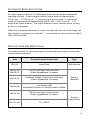
APPLICATIONS AND PROTOCOLS
The model number on each scan engine includes the scan engine number and
communications protocol.
Unit Communication Protocol(s) Type
IS4110 Laser Data Non-decode
IS4125-41
IS4125-76
RS232 and Light Pen Emulation
(Flash Upgradeable Firmware)
IS4125-47
Keyboard Wedge, Stand Alone Keyboard
(Flash Upgradeable Firmware)
IS4125-38
Low Speed USB
Keyboard Emulation or Serial Emulation Mode
Decode
Standard
IS4125-63
RS232 and Light Pen Emulation
(Flash Upgradeable Firmware)
IS4125-163 TTL, RS232
Decode
High-Density

6
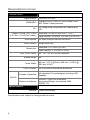
DESIGN SPECIFICATIONS
OPERATIONAL
Light Source: VLD 650 ± 10 nm
CDRH/IEC:
Designed to be used in CDRH Class II and
IEC Class 2 laser products
UL:
UL recognized component for Canada and
US
Standard: 25 mm to 200 mm (1" to 8")
Depth of Field, UPC 100%
(0.33 mm (13 mil) bar codes):
High Density: 10 mm to 175 mm (0.4" to 6.9")
Scan Speed: 52 scan lines per second minimum
Scan Pattern: Single scan line
Standard: 0.173 mm (6.8 mil)
Resolution:
High Density: 0.132 mm (5.2 mil)
Roll, Pitch, Skew: 30°, 56°, 58° at 100 mm distance
Sweep Angle: 60°
Scan Width:
40 mm (1.57") @ Face; 280 mm (11.00") @
200 mm (8.00")
Print Contrast: 35% minimum reflectance difference
Decode Capability:
All standard 1D symbologies including GS1
DataBar
IS4125
System Interfaces:
RS232C, Light Pen Emulation,
Keyboard Wedge, Low Speed USB,
RS232 TTL
MAINTENANCE
Window: Clean Periodically
Specifications are subject to change without notice.

7
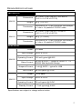
DESIGN SPECIFICATIONS
MECHANICAL
Dimensions:
45.7 mm L x 40.6 mm W x 18.5 mm D
(1.8" L x 1.6" W x 0.73" D)
Weight: 53 g. (1.87 oz.)
IS4125
Termination:
Low profile ZIF 12-pin connector that accepts
a 1 mm x 12 position FFC/FPC cable
Dimensions:
45.7 mm L x 40.6 mm W x 14 mm D
(1.8" L x 1.6" W x 0.55" D)
Weight: 45 g. (1.774 oz.)
IS4110
Termination:
Low profile ZIF 10-pin connector that accepts
a 1 mm x 12 position FFC/FPC cable
ELECTRICAL
Power: 0.6 watts
Input Voltage: 5VDC ± 0.25V
Operating Current: 120 mA typical @5VDC
Sleep Current:
22 mA @ 5VDC – typical for RS232 C, TTL
RS232 and Keyboard Wedge
Suspend Current: 1 mA @ 5VDC – typical for USB
IS4125
Idle Current: 58 mA typical @ 5VDC
Power: 0.375 watts
Input Voltage: 5VDC ± 0.25V
Operating Current: 75 mA typical @ 5VDC
IS4110
Standby Current: 1.7 mA typical @ 5VDC
Specifications are subject to change without notice.

8
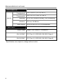
DESIGN SPECIFICATIONS
ENVIRONMENTAL
Operating
Temperature:
-20°C to 50°C (-4°F to 122°F)
Storage
Temperature:
-40°C to 70°C (-40°F to 158°F)
Humidity: 5% to 95% relative humidity, non-condensing
Vibration: 7G over 10-500 Hz
IS4125
Light Levels: Up to 60,000 Lux (5,574 footcandles)
COMPLIANCE
Laser Class: Class 2; IEC 60825-1, EN 60825-1
IS4110 EMC: FCC Part 15, ICES-003, EN 5022 Class A
IS4125 EMC: FCC Part 15, ICES-003, EN 5022 Class B
Specifications are subject to change without notice.

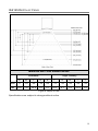
IS4125 DEPTH OF FIELD
Minimum Bar Code Element Width
Standard High Density
A B C D E F G H I J
mm .17 .19 .25 .33 .53 .13 .16 .18 .25 .33
mil 6.8 7.5 10.4 13 21 5.2 6.1 7.2 10.4 13
Figure 4. Depth of Field
Specifications are subject to change without notice.
9

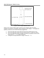
IS4125 OBJECT DETECTION
Figure 5. IS4125 Object Detection Field
Please note certain ambient light conditions may interfere with the object
detection mechanism, resulting in false activation of the engine. To mitigate the
problem, please try one of the following suggestions:
1. Avoid mounting the engine directly facing the ambient light source.
2. Avoid mounting the engine facing a light-colored or reflective surface.
3. Avoid mounting the engine towards a surface at a distance close to the
long range (9" – 11") of object detection
4. Configure the object detection range to short (4" – 7").
10

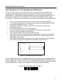
DESIGN SPECIFICATIONS
Specifications for the Supplemental Window
In applications where a secondary window is installed with the IS4125, the
following recommendations should be followed in order to achieve the best
performance. While these recommendations provide general guidelines for a
successful integration and installation, it will take some testing to find exact
parameters to optimize scan performance and auto detection in each application.
The window should be tempered or chemically strengthened glass.
The window should be of optical quality and have a transmission of 98%
or greater between 600 nm – 700 nm.
The window should be optically flat, clear, and free of inclusions,
scratches and pits.
The window should not have birefringence.
The window should have an anti-reflective coating on both sides to
minimize "ghost" images or reflections.
The window should not be thicker than 2.0 mm.
The window and the engine should be mounted in a way to avoid direct
reflections of both the laser beam and LED of the object detection from
hitting the scan engine.
The angle between the window and the engine should be approximately
15° to 20°, but should be adjusted as needed. See Figure 6.
Figure 6. Supplemental Window Angle
In rare instances where a supplemental window was previously installed and the
factory default long range is enabled, the new object detection mechanism may
behave differently. If this occurs, scan the Enable Short Range Object Detection
bar code below to configure the engine to short range object detection.
Enable Short Range Object Detection
³118711
11

12
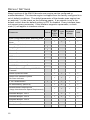
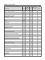
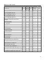
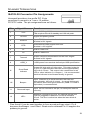
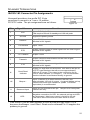
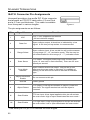
DEFAULT SETTINGS
Many functions of the IS4125 decode scan engine can be configured or
enabled/disabled. The decode engine is shipped from the factory configured to a
set of default conditions. The default parameter of the decode scan engine has
an asterisk (*) in the charts on the following pages. If an asterisk is not in the
default column then the default setting is OFF or disabled. Every interface does
not support every parameter. If the interface supports a parameter, a check
mark (
) will appear in interface column.
Parameter Default
RS232
OR
RS232
TTL
Light
Pen
Keyboard
Wedge
USB
Enter Configuration Mode, After Any Scan
*
Enter Configuration Mode, Only on First
Scan
Short Range Activation
Long Range Activation
*
Normal Scan
*
Custom Scan
DTR Activation
DC2 Activation
Address Based Activation
“NOREAD” message Transmission
Turn on Green LED during “NOREAD”
Transmit
*
Same Symbol Re-scan
*
Green LED Identical Symbol
Re-Scan Indicator
1 Vs 2 Scan Buffers 1
2X Redundancy (MECCA)
Double Border Requirement
(Large Intercharacter Space Requirement)
Alternate Beeper Tone 1
Alternate Beeper Tone 2
*
Alternate Beeper Tone 3
No Beeper tone
Two Second Timeout

13
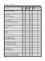
DEFAULT SETTINGS
Parameter Default
RS232
OR
RS232
TTL
Light
Pen
Keyboard
Wedge
USB
No Two Second Timeout
*
Razzberry Tone on Timeout
No Tone on Timeout
*
Three Beeps on Timeout
Beep Before Transmit
*
Beep After Transmit
Baud Rate 9600
Parity Space
8 Data Bits
7 Data Bits
*
RTS/CTS
Character RTS/CTS
*
Message RTS/CTS
ACK/NAK
XON/XOFF
*
No Intercharacter Delay
1 Millisecond Intercharacter Delay
5 Millisecond Intercharacter Delay
10 Millisecond Intercharacter Delay
25 Millisecond Intercharacter Delay
100 Millisecond Intercharacter Delay
DTR Input
DTR Scan Disable
“DE” Disable Command
LRC Calc+ Transmit RS232
Start LRC on first RS232 Byte
Start LRC on Second RS232 Byte
*
Carriage Return
*
Line Feed
*
STX Prefix
ETX Suffix
Tab Prefix
Tab Suffix

14
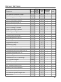
DEFAULT SETTINGS
Parameter Default
RS232
OR
RS232
TTL
Light
Pen
Keyboard
Wedge
USB
Prefix ID for UPC/EAN
Suffix ID for UPC/EAN
Bars High
*
Spaces High
Transmit as Scanned
*
Transmit as code 39
Poll Light Pen 5 volts
No Poll Light Pen
*
Reverse Polarity Idle for Light Pen
UPC
*
EAN
*
Full ASCII code 39
Code 39
*
Codabar
Code 128
*
Code 93
*
Code 11
GS1 DataBar Enable
GS1 DataBar ID “]e0”
*
GS1 DataBar App ID “01”
*
GS1 DataBar Check Digit
*
GS1 DataBar Expanded Enable
Expanded ID “]e0”
*
GS1 DataBar Limited Enable
GS1 DataBar Limited ID “]e0”
*
GS1 DataBar Limited App ID “01”
*
GS1 DataBar Limited Check Digit
*
Interleaved 2 of 5
*
Hong Kong Matrix 2 of 5
Airline 2 of 5
Minimum 1 Character Code Length
Minimum 3 Character Code Length
*
Minimum 6 character Code Length

15
DEFAULT SETTINGS
Parameter Default
RS232
OR
RS232
TTL
Light
Pen
Keyboard
Wedge
USB
Set Minimum Character Length
Set Character Lock Length
Transmit UPC-A Number Sys
*
UPC-A Check Digit Transmit
*
Convert UPC-A to EAN-13
Expand UPC-E
UPC-E Check Digit Transmit
UPC-E Leading 0 Transmit
EAN-8 Check Digit Transmit
*
EAN-13 Check Digit Transmit
Convert EAN-8 to EAN-13
“$” Prefix ID for UPC/EAN
2 Digit Supplements (Scan)
5 Digit Supplements (Scan)
Bookland (Scan)
Supplement Required
Bookland to ISNB
Transmit ISBN CD
Mod 43 Check digit-Code 39
Transmit Mod 43 Check Digit Code 39
*
Transmit Start/Stop-Code 39
CLSI Editing (Enable)
ITF Check Digit
Transmit Mod 10 ITF Check Digit
2 of 5 Symbol Lengths Variable
ISBN Reformatting
Coupon Code 128
]C1 Transmit Coupon C128
Coupon 128 Group Separator
Italian Pharmaceutical
Codabar Start & Stop Class
ITF Minimum Symbol Length Test
Matrix 2 of 5

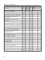
16
DEFAULT SETTINGS
Parameter Default
RS232
OR
RS232
TTL
Light
Pen
Keyboard
Wedge
USB
Matrix 2 of 5 Check Digit
Hong Kong Matrix 2 of 5
MSI-Plessy Test of Check Digit
*
Enable MSI-Plessy Mod 10 Check Digit
Enable MSI-Plessy Mod 10/10
Check Digit
Transmit MSI-Plessy Check Digit
*
UK Plessy
UK Plessey Check Digit
UK Plessey Special Format
A to X conversion (UK)
Scan Count Test Mode
Scanability Test Mode
Normal Scan/Operating Test Mode
Default to ScanPal Communication
parameters Code ID
Code ID
Sanyo 635 ECR Protocol
Post Software ID characters
“Newcode” Mode A
“Newcode” Mode B
SNI Beetle Mode
BIO DATA Mode
Enable Sineko Mode
Enable Caps Lock Mode
(for MI951 external wedge)
Rochford Thompson Mode
RTS Counter Toggle
Beep on BEL RS232
Page is loading ...
Page is loading ...
Page is loading ...
Page is loading ...
Page is loading ...
Page is loading ...
Page is loading ...
Page is loading ...
Page is loading ...
Page is loading ...
Page is loading ...
Page is loading ...
Page is loading ...
Page is loading ...
Page is loading ...
Page is loading ...
Page is loading ...
Page is loading ...
Page is loading ...
Page is loading ...
-
 1
1
-
 2
2
-
 3
3
-
 4
4
-
 5
5
-
 6
6
-
 7
7
-
 8
8
-
 9
9
-
 10
10
-
 11
11
-
 12
12
-
 13
13
-
 14
14
-
 15
15
-
 16
16
-
 17
17
-
 18
18
-
 19
19
-
 20
20
-
 21
21
-
 22
22
-
 23
23
-
 24
24
-
 25
25
-
 26
26
-
 27
27
-
 28
28
-
 29
29
-
 30
30
-
 31
31
-
 32
32
-
 33
33
-
 34
34
-
 35
35
-
 36
36
-
 37
37
-
 38
38
-
 39
39
-
 40
40


Ask a question and I''ll find the answer in the document
Finding information in a document is now easier with AI
Related papers
-
Metrologic ScanQuest IS4110 User manual
-
Honeywell 7820 User manual
-
-
-
Metrologic MS3780 User manual
-
Metrologic Orbit MS7120-38 User manual
-
-
Metrologic Orbit MS7120 User guide
-
-
Metrologic 7600 User manual