Page is loading ...

Centrometal d.o.o. - Glavna 12, 40306 Macinec, Croatia, tel: +385 40 372 600, fax: +385 40 372 611
HEATING TECHNIQUE
Technical instructions
using of REGULATION
hot water boiler PelTec / PelTec-lambda
THE FIRST START-UP MUST BE DONE BY AUTHORIZED PERSON
OTHERWISE PRODUCT WARRANTY IS NOT VALID
O2=8%
PelTec 12-48
PelTec-lambda 12-96
80°C
120°C
0%
1700
15k
30%
60°C
70°C
50°C
55°C
READY
TU-RPLT/PLT-L-02-2020-v2.86i-ENG
ENG

Technical instructions REGULATION PelTec / PelTec-lambda
2
Screen
After turning on the main switch, screen will display language selection menu and software version.
You can choose between 12 languages, Croatian, French, Portuguese, English, Slovenian, Italian,
Serbian, German, Czech,Hungarian, Slovakian and Spanish. To select the language, press the flag
of language you want.
Software version
Language selection
SWITCHING ON
If the language selection is "disabled" (display -> language sel -> disabled), initial message wil
appear in the screen as long as the set in the menu "Welcome time" (display -> welcome time).
Button’’OK’’
Initial message duration
(countdown)
Software version
Boiler power
(12, 18, 24, 36, 48, 69, 96 kW)
Boiler power
(12, 18, 24, 36, 48, 69, 96 kW)
When turning the main switch the screen should not be pressed (by finger ...). If
the screen when you turn the main switch is pressed (on the screen labeled
"Firmware update ') regulation is in ”software update“ that can be used by
authorized personnel only. If this happens, it is necessary to turn off the main
switch and restarted without any pressure on the display.
Possibility of online boiler
monitoring and online boiler
management.
(Additional equipment- it is
necessary to order a Wi-Fi module.)

Start/stop boiler
State of the current
boiler status
BUTTONS
Button ’’START’’/’’STOP’’
Technical instructions REGULATION PelTec / PelTec-lambda
3
Main Menu, Buttons
MAIN MENU
Time
Button ’’ON / OFF’’
options: on / off boiler operation
Button ’’DISPLAY SELECTION’’
options: main menu / work
Button ’’BOILER OPERATION DISPLAY’’
options: graphic / numeric /
additional equipment
Button ’’ENTER’’
Button ’’BACK’’
Button ’’PREVIOUS SCREEN’’
Button ’’NEXT SCREEN’’
Button ’’OK’’
Navigation buttons:
’’LEFT’’, ’’RIGHT’’, ’’UP’’, ’’DOWN’’
Button ’’DELETE’’
Button ’’FACTORY SETTINGS’’
Button ’’INFORMATION’’
Button ’’COPY’’ Button ’’PASTE’’
Display selection:
Main menu / work
Boiler operation display :
graphic/numeric
additional equipment
The main menu is used to select the desired submenu. To select a specific menu you must press the
appropriate icon on the screen. To switch between the ’’Main menu’’ and ’’Boiler working display’’
press the button ’’Display selection’’. To switch between graphic and numeric display of the boiler
using press ’’Boiler operation display’’.
Date

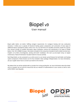
Screen, Symbols
SYMBOLS
1 - Boiler
2 - Pellet tank
3 - Pellet feeding screw
4 - 4-way mixing valve with motor device
(when working, left/right arrow will be shown)
5 - Symbol of fan operation
(when working, symbol is turning)
6 - Fan speed (rpm)
7 - Symbol of flue gas channel cleaner
(when working, symbol is moving)
8 - Symbol of electric heater
(when working, symbol changes color)
9 - Symbol of pellet feeding screw
(when working, symbol is moving)
10 - Symbol of mechanism for grate cleaning
(when working, symbol moves left/right)
11 - Current position of burner grate
(0% - closed, 100% - open)
12 - Pellet level in the tank (3 levels)
13 - Boiler temperature sensor
14 - Flue gas sensor
15 - Flow temperature sensor
16 - Resistance of photocell (luminous intensity
of flame)
17 - Flame (symbol appears when there is the flame)
18 - Symbol of microswitch in mechanism for
grate cleaning
19 - Percentage of openes of the 4-way mixing
valve with motor device
(0% - closed, 100% - open)
20 - The percentage of oxygen in the flue gases
21 - The symbols in this section depend on the
selected configuration
22 - External control symbol (see point 13.1)
23 - Suction system symbol (off, pause, on)
24 - Outdoor temperature sensor
25 - Ash screw (only 69/96) (additional equipment)
26 - Rotary valve (additional equipment)
27 - Screw refill (additional equipment)
28 - Percentage of fuel level (if FUEL LEVEL is ON)
29 - Fuel level percentage reset button
(if FUEL LEVEL is ON)
4
*
*
***
**Displaying these symbols depends on the configuration set up by an authorized service
***For more informations about this symbol see ”Technical instructions for vacuum wood pellet feeding system“.
Technical instructions REGULATION PelTec / PelTec-lambda
*
*
*
*Only on PelTec-lambda
**
**
**
80°C
120°C
14
4
5
6
7
16
1011
9
2
21
17
1
18
30%
60°C
3
13
22
*
*
12
23
*
O2=8%
20
*
**
**
10°C
19
24
8
25
15
26
9
27
**
**
**
28
29

0% 0%
Feeding
screw
80°C
0%
1700
>1M
80°C
0%
1700
15k
Pellets
falling
60°C 60°C 60°C
Screen, Symbols
SYMBOLS
4-way mixing valve with actuator
Actuator doesn’t work Actuator is closing
the valve
Actuator is opening
the valve
Pellet feeding screw
Pellet feeding screw doesn’t work
Pellet feeding screw is working
(pellets are falling and screw is moving)
Flame symbol
There is no flame
There is a flame
Technical instructions REGULATION PelTec / PelTec-lambda
5

Symbols, Configuration symbols
CONFIGURATION SYMBOLS
80°C
120°C
0%
1700
15k
30%
60°C
The following symbols are shown on the display configuration
(page 4, mark 20 in the figure)
The pump has a request for work (next to the pump symbol bright yellow square when
the consumer given the demand for work the pump, the pump does not work if you have
not met all the conditions for work, for example. low temp. in the boiler, otherwise the
pump normally works)
20
Pump (when pump is working symbol is rotating, otherwise idle)
Pellet level in the tank (3 levels)
Empty
- error
Half-empty
- warning
Full
0%
100%
Position of burner grate
Closed
(ready to work)
Open
(cleaning)
6
Technical instructions REGULATION PelTec / PelTec-lambda
O2=8%
05:08
OFF

Configuration symbols
Accumulation tank with current
temperature at top of the tank and
at the bottom of the tank.
Hydraulic crossover with the
current temperature
Domestic hot water tank
with current temperature
Heating circuit
Room thermostat
Next to the room thermostat
symbol bright blue circle (the
room thermostat has requested
for operating the pump, the pump
does not work if you have not met
all the conditions for its operation,
for example. low temp. in the
boiler, otherwise normally works)
Boiler flow temperature
3-way diverter valve (showing the
open and closed pipe)
55°C
70°C
70°C
50°C
60°C
’’Chimney sweeper’’ option
enabled
Technical instructions REGULATION PelTec / PelTec-lambda
7
Heating + DHW mode
Working modes
Only DHW mode
Only Heating mode
Automatic mode
(automatic switch between
working modes Heating+DHW and
only DHW mode)
Freeze guard enabled
Freeze guard active
Boiler is started because
of freeze guard option
D6
% of grate opening (0%=closed)
when grate is at 0% red symbol
must be shown
% of grate opening (100%=open)
when grate is at 100% red
symbol must be shown
0%
100%
symbols for opening/closing the
grate ( =closing / =opening)

Maintenance, Cleaning the boiler
1.0. MAINTENANCE
1.1. CLEANING THE BOILER
2
3
1
4
5
Cleaning the boiler - By pressing the button ’’START’’ (1) fan will begin work (2), an burner grate (3)
will move into the open position (100%) (4), (button ’’START’’ will become a button’’STOP’’).
This option enables you to during cleaning of combustion chamber, boiler ash does not come out of
the boiler, and since the burner grate is open ash falls into the ash box. After cleaning, it is necessary
to press the ''STOP'' to shut off the fan and burner grate move back to the closed position (0%) (4)
(same thing will happen if you press the button ''BACK'' (5)) . After cleaning, it is necessary to empty
the ashtray.
8
Technical instructions REGULATION PelTec / PelTec-lambda

Filling at start, System airvent
1.2. FILLING AT START
Filling at start - by pressing ''START'' (1) pellet feeding screw starts to operate (2) (works 25 min),
and the burner grate (3) moves to the open position (100%) (4) to make pellets fell down in ashtray
After this process is complete pellet feeding screw stops working, the burner grate is returned to the
closed position (0%) (4). After completion of the initial filling of pellets ashtrays need to put in pellet
tank. For the duration of this process, the display shows the countdown process duration (5). Before
starting this process, it is necessary to fill the pellet tank. The process may be interrupted by pressing
button ''STOP'' or ''BACK'' (6).
1.3. SYSTEM AIRVENT
System airvent - entering the above menu, the motor device of 4-way mixing valve opens the valve
to 50%(1). By pressing START'' next to a particular pump symbol, the pump starts to work (2, 3, 4)
(button ’’START’’ become button ’’STOP’’). By pressing the button ''STOP'' the pump stops working.
In this option is possible to work 2 or 3 pumps at the same time.
1
2
3
4
Technical instructions REGULATION PelTec / PelTec-lambda
9
3
2
5
1
6
4

Temperatures
2.0. TEMPERATURE
Temperatures choice depends on the configuration of heating. Below are shown all types of
installation and configuration.
CONFIGURATION 1 - DOMESTIC HOT WATER (DHW)
Scheme of configuration
On the screen
10
Technical instructions REGULATION PelTec / PelTec-lambda
1 - Boiler PelTec / PelTec-lambda
2 - Air self-venting group 2,5 bar
3 - Motor 4-ways mixing valve
4 - Closed type expansion vessel
5 - Return flow sensor
6 - DHW tank
7 - DHW sensor
8 - Outdoor sensor
3
M
bar
2
4
5
CW
P1
6
1
7
Required sensors: - return flow temp. sensor
- DHW sensor
Scheme 1. Configuration DHW
8

Temperatures (DHW)
2. TEMPERATURES (CONFIGURATION DHW)
2.1 / 2.3 DHW TEMP.
2.2 / 2.4 DIFFERENTIAL OF DHW
default: 50°C
Minimum: 40°C
Maximum: 80°C
Temperature setting options of DHW (domestic hot water).
Possible selection:
default: 5°C
Minimum: 4°C
Maximum: 40°C
The possibility of setting domestic hot water diference.
Possible selection:
Technical instructions REGULATION PelTec / PelTec-lambda
11
12-48
69/96
2.1 MAX. BOILER TEMP. (ONLY 69/96)
default: 75°C
Minimum: 75°C
Maximum: 80°C
The possibility of setting maximum boiler temperature.
Possible selection:
2.2 DIFF. BOILER (ONLY 69/96)
default: 8°C
The view of boiler difference setting (not possible to change).
Possible selection:

Temperatures (DHC)
CONFIGURATION 2 - DIRECT HEATING CIRCUIT (DHC)
Scheme of configuration
On the screen
12
Technical instructions REGULATION PelTec / PelTec-lambda
3
6
bar
2
4
5
1 - Boiler PelTec / PelTec-lambda
2 - Air self-venting group 2,5 bar
3 - Motor 4-ways mixing valve
4 - Closed type expansion vessel
5 - Return flow sensor
6 - Flow temperature sensor
7 - Heating circuit
8 - Room thermostat
9 - Outdoor sensor
P1
1
M
P2
7
8
Required sensors: - return flow temp. sensor
- flow temperature sensor
Scheme 2. Configuration DHC
9

Temperatures (DHC)
2. TEMPERATURE (CONFIGURATION DHC)
default: 60°C
Minimum: 30°C
Maximum: 90°C
The possibility of setting main flow temperature.
2.1 / 2.3 MAIN FLOW TEMP.
Possible selection:
Technical instructions REGULATION PelTec / PelTec-lambda
13
12-48
69/96
2.1 MAX. BOILER TEMP. (ONLY 69/96)
default: 75°C
Minimum: 75°C
Maximum: 80°C
The possibility of setting maximum boiler temperature.
Possible selection:
2.2 DIFF. BOILER (ONLY 69/96)
default: 8°C
The view of boiler difference setting (not possible to change).
Possible selection:

Temperatures (DHC II DHW)
CONFIGURATION 3 - DHC || DHW
Scheme of configuration
On the screen
14
Technical instructions REGULATION PelTec / PelTec-lambda
1 - Boiler PelTec / PelTec-lambda
2 - Air self-venting group 2,5 bar
3 - Motor 4-ways mixing valve
4 - Closed type expansion vessel
5 - Return flow sensor
6 - Flow sensor
7 - DHW tank
8 - DHW tank sensor
9 - Heating circuit
10 - 3-way diverter valve
11 - Room thermostat
12 - Outdoor sensor
3
M
6
bar
2
4
5
CW
P2
P1
7
1
9
P
P3
10
8
11
Required sensors: - return flow temp. sensor
- flow temperature sensor
- DHW sensor
Scheme 3. Configuration DHC || DHW
12

2. TEMPERATURE (CONFIGURATION DHW || DHC)
2.1 / 2.3 DHW TEMP.
2.2 / 2.4 DIFFERENTIAL OF DHW
default: 50°C
Minimum: 40°C
Maximum: 80°C
Temperature setting options of DHW (domestic hot water).
Possible selection:
default: 5°C
Minimum: 4°C
Maximum: 40°C
The possibility of setting differential of DHW.
Possible selection:
default: 60°C
Minimum: 30°C
Maximum: 90°C
The possibility of setting main flow temperature
2.3 / 2.5 MAIN FLOW TEMP.
Possible selection:
Technical instructions REGULATION PelTec / PelTec-lambda
15
2.1 MAX. BOILER TEMP. (ONLY 69/96)
default: 75°C
Minimum: 75°C
Maximum: 80°C
The possibility of setting maximum boiler temperature.
Possible selection:
2.2 DIFF. BOILER (ONLY 69/96)
default: 8°C
The view of boiler difference setting (not possible to change).
Possible selection:
12-48
69/96
Temperatures (DHC II DHW)

Temperatures (BUF)
CONFIGURATION 4 - ACCUMULATION TANK
Scheme of configuration
On the screen
16
Technical instructions REGULATION PelTec / PelTec-lambda
1 - Boiler PelTec / PelTec-lambda
2 - Air self-venting group 2,5 bar
3 - Motor 4-ways mixing valve
4 - Closed type expansion vessel
5 - Back flow sensor
6 - Accumulation tank CAS
7 - Accumulation tank sensor CAS 1 (upper)
8 - Accumulation tank sensor CAS 2 (lower)
9 - Outdoor sensor
3
bar
2
4
5
P1
6
7
8
1
M
Required sensors: - return flow temp. sensor
- accumulation tank sensor (upper)
- accumulation tank sensor (lower)
Scheme 4. Configuration BUF
NOTES:
- In this configuration is possible to upgrade up to 4 unit "CM2K module for regulation 2 heating circuits“.
- In this configuration is possible to connect external control (external start)
9

2. TEMPERATURE (CONFIGURATION BUF)
default: 80°C
Minimum: 40°C
Maximum: 85°C
The possibility of setting the desired temperature of the accumulation tank.
2.1 / 2.3 BUFFER TANK TEMP.
default: 20°C
Minimum: 5°C
Maximum: 64°C
The possibility of setting the minimum temperature of the accumulation tank. When minimum temperature of
accumulation tank (upper sensor) is reached, all heat pumps connected to the boiler control will be shut down.
The minimum accumulation tank temperature does not affect the operation of the DHW pump.
2.2 / 2.4 MIN. BUF. TANK TEMP.
default: 10°C
Minimum: 5°C
Maximum: 30°C
The possibility of setting the accumulation tank start difference.
2.3 / 2.5 DIFF. BUF. TANK TEMP.
Possible selection:
Possible selection:
Possible selection:
Technical instructions REGULATION PelTec / PelTec-lambda
17
default: 5°C
Minimum: 3°C
Maximum: 30°C
The possibility of setting the accumulation tank stop difference.
2.4 / 2.6 DIFF. STOP BUF. TANK
Possible selection:
12-48
69/96
2.1 MAX. BOILER TEMP. (ONLY 69/96)
default: 85°C
Minimum: 80°C
Maximum: 90°C
The possibility of setting maximum boiler temperature.
Possible selection:
Temperatures (BUF)

18
Technical instructions REGULATION PelTec / PelTec-lambda
2.2 DIFF. BOILER (ONLY 69/96)
default: 8°C
The view of boiler difference setting (not possible to change).
Possible selection:
Description of work:
The regulation reads on the upper sensor accumulation tank temperature, minimum accumulation tank
temperature and accumulation tank difference. At the bottom sensor, regulation reads the accumulation tank
shutdown difference that can be set in the installation menu (under PIN). When the boiler is switched on, it
works until the temperature on the lower sensor (T accumulation tank - T accumulation tank shutdown
difference) is reached. The boiler will turn ON again when accumulation tank upper temperature (upper
sensor) reach the (T accumulation tank - T accumulation tank difference).
Temperatures (BUF)

1 - Boiler PelTec / PelTec-lambda
2 - Air self-venting group 2,5 bar
3 - Motor 4-ways mixing valve
4 - Closed type expansion vessel
5 - Return flow sensor
6 - DHV tank
7 - DHW tank sensor
8 - Accumulation tank CAS
9 - Accumulation tank sensor CAS 1 (upper)
10 - Accumulation tank sensor CAS 2 (lower)
11 - 3-way diverter valve
12 - Outdoor sensor
3
M
bar
2
4
5
CW
P1
1
P
P3
11
7
8
9
10
6
Required sensors: - return flow temp. sensor
- DHW tank sensor
- accumulation tank sensor (upper)
- accumulation tank sensor (lower)
Scheme 5. Configuration DHW || BUF
NOTE:
In this configuration is possible to upgrade up to 4 unit "CM2K module for regulation 2 heating circuits“.
12
Temperatures (DHW II BUF)
CONFIGURATION 5 - DHW||BUF
Scheme of configuration
On the screen
Technical instructions REGULATION PelTec / PelTec-lambda
19

default: 10°C
Minimum: 5°C
Maximum: 30°C
The possibility of setting the accumulation tank start difference.
2. TEMPERATURE (CONFIGURATION DHW || BUF)
default: 80°C
Minimum: 40°C
Maximum: 85°C
The possibility of setting the desired temperature of the accumulation tank.
2.1 / 2.4 BUFFER TANK TEMP.
default: 20°C
Minimum: 5°C
Maximum: 64°C
The possibility of setting the minimum temperature of the accumulation tank.
2.2 / 2.5 MIN. BUF. TANK TEMP.
2.3 / 2.6 DIF. BUF. TANK TEMP.
Possible selection:
Possible selection:
Possible selection:
20
Technical instructions REGULATION PelTec / PelTec-lambda
12-48
69/96
default: 10°C
Minimum: 5°C
Maximum: 30°C
The possibility of setting the accumulation tank stop difference.
2.4 / 2.7 DIF. STOP BUFF. TANK TEMP.
Possible selection:
Temperatures (DHW II BUF)
/