Page is loading ...

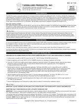
*) Low voltage line, lay separately from power cables!
W1: Power supply
W2: Control signal for fan and actuators
W3:Collectivefaultmessage,onlywith2-pipeunits,non-floating,24VDC/max.0.5A
The number of connecting wires required including fuses is given on the individual control units. Electrical
supply: Observe the technical connection requirements laid down by the utility companies!
3
W1
GND
GND
1
Uc1
0-
10V
2
3
3
W2
GND
GND
3
Uc2
0-
10V
4
GND
AI2
1
2
N
PE
L
1
2
3
GND
AI3
3
4
GGNNDD
VV11
GGNNDD
VV22
GND
V+
Tx
Tx
GND
AI1
GND
AI2
1
2
N
PE
L
1
2
3
GND
AI3
3
4
GND
V+
Tx
Tx
GND
AI1
GGNNDD
VV11
GGNNDD
VV22
44**
44**
44**
GGNNDD
VV22
GGNNDD
VV22
111
222
111
222
222
WWW333
222
WWW333
242424VVVDDDCCC111
222
GGGNNNDDD
242424VVVDDDCCC111
222
GGGNNNDDD
Cabling – KaControl actuation BMS, KaControl
Mains power
230 V AC/50 Hz
Fuse by others
max. 16 A
KaCool D AF
EC fan
Unit 1
230 V AC/50 Hz
KaControl
KaCool D AF
EC fan
Unit n
230 V AC/50 Hz
KaControl
AI: Ri = 20 kOhm AI: Ri = 20 kOhm
- Optional -
Cooling
actuator
- Optional -
Cooling
actuator
Heating/Cooling
actuator
Heating/Cooling
actuator
24 V DC/
max. 0.5 A
24 V DC/
max. 0.5 A
2-pipe: Uc1 = Heating/Cooling (0..10 V DC)
Uc2 = ---
4-pipe: Uc1 = Cooling (0..10 V DC)
Uc2 = Heating (0..10 V DC)
Collective fault
message
Unit 1 only with
2-pipe
Collective fault
message
Unit n only with
2-pipe
Automation station
KaCool D

Stand-alone unit, KaControl
*) Lay shielded cable e.g. B. J-Y(St)Y, 0.8 mm separately from power cables.
**) Lay shielded data cable, twisted pairs, e.g. UNITRONIC® BUS LD 2 x 2 x 0.22 mm² or similar, linear but separate from power lines.
W1: Power supply
W2:AnalogueinputAI1(optionallyconnectible),max.cablelength10m,from1mm²30m,disconnectfactory-fittedintakesensor.
W3: Digital input DI1 (optionally connectible), max. cable length 30 m, from 1 mm² 100 m
W4: Bus signal (tLan), max. cable length 30 m
W5: Analogue input A1 (optionally connectible), max. cable length 10 m, from 1 mm² 30 m
3
W1
DI
COM
1
2
2* W3
3**
GND
3
GND
24V
24V
1
Tx+
Tx+
2
3
W4
GN D
AI2
1
2
N
PE
L
1
2
3
GN D
AI3
GN D
V+
3
2
T x
T x
1
GN D
AI1
GN D
V1
GN D
V1
GN D
V2
GN D
V2
DI 2
GN D
1
2
1
2
1
2
1
2
1
2
1
2
3**
GND
3
GND
24V
24V
1
Tx+
Tx+
2
3
W4
GN D
AI2
1
2
N
PE
L
1
2
3
GN D
AI3
GN D
V+
3
2
T x
T x
1
GN D
AI1
GN D
V1
GN D
V2
DI 2
GN D
1
2
1
2
1
2
1
2
1
2
1
2
1
2
1
2
1
2
W2
2*2*
W2
2*
1
2
1
2
W2
2*
1
2
1
2
1
2
1
2
1
2
1
2
W5
2*2*
W5
2*
1
2
1
2
W5
2*
1
2
1
2
1
2
1
2
1
2
1
2
W5
2*2*
W5
2*
1
2
1
2
W5
2*
KaController 24 V
3210021,
3210022
or
3210026
Mains power
230 V AC/50 Hz
Fuse by others
max. 16 A
- Optional -
Room sensor
Type 3250110
vertical installation,
e.g. on a wall in the
temperature zone
- Optional -
External contact
On/Off
Parametrisable
function,
e.g. ON/OFF
changeover
KaCool D AF
230 V AC/50 Hz
KaControl
- Optional -
Cooling
actuator
Heating/Cooling
actuator
- Optional -
Clip-on sensor
Type 3250115
for H/C changeover with
2-pipe systems.
Only in conjunction with a
3-way valve
- Optional -
Clip-on sensor
Type 3250115
with 4-pipe systems
Only in conjunction with a
3-way valve
AI: Ri = 20 kOhm
KaCool D

KaControl group formation max. 6 units or 30 units with CAN bus card
*) Lay shielded cable e.g. B. J-Y(St)Y, 0.8 mm separately from power cables.
**) Lay shielded data cable, twisted pairs, e.g. UNITRONIC® BUS LD 2 x 2 x 0.22 mm² or similar, linear but separate from power lines.
W1: Power supply
W2:AnalogueinputAI1(optionallyconnectible),max.cablelength10m,from1mm²30m,disconnectfactory-fittedintakesensor
W3: Digital input DI1 (optionally connectible), max. cable length 30 m, from 1 mm² 100 m
W4, W6: Bus signal (tLan), max. cable length in each case 30 m
W5: Bus signal (CAN bus)
3**
W6
2**
3
W1
GND
3
GND
24V
24V
1
Tx+
Tx+
2
1
2
1
2
2*
DI
COM
1
2
W6
W5
2* 3 2**
33
W2
W3
W1
3**
W5
3**
Einkreisregelung bis 6 Geräte:
Leitung W6 erforderlich, gesamte maximale Leitungslänge 30 m.
Leitung W5 enällt.
Einkreisregelung bis 30 Geräte:
CANbus-Karte und Leitung W5 erforderlich, gesamte maximale Leitungslänge 500 m.
Leitung W6 enällt.
W4
GN D
AI2
N
PE
L
1
2
3
GN D
AI3
GN D
V+
2
T x
T x
1
1
+
-
GND
3
1
2
GN D
AI2
GN D
AI1
1
2
N
PE
L
1
2
3
GN D
AI3
GN D
V+
3
2
T x
T x
1
1
+
-
GND
GN D
DI 2
1
2
GN D
AI2
N
PE
L
1
2
3
GN D
AI3
GN D
V+
T x
T x
1
+
-
GND
3
1
2
GN D
AI2
W1
GN D
V1
GN D
V1
GN D
V2
GN D
V2
GN D
V1
GN D
V1
GN D
V2
GN D
V2
GN D
V1
GN D
V1
GN D
V2
GN D
V2
KaController 24 V
3210021,
3210022
or
3210026
Mains power
230 V AC/50 Hz
Fuse by others
max. 16 A
- Optional -
Room sensor
Type 3250110
vertical installation,
e.g. on a wall in the
temperature zone
KaCool D AF
Unit 1
230 V AC/50 Hz
KaControl
KaCool D AF
Unit 2
230 V AC/50 Hz
KaControl
KaCool D AF
Unit n
230 V AC/50 Hz
KaControl
- Optional -
Cooling
actuator
- Optional -
Cooling
actuator
- Optional -
Cooling
actuator
CAN bus card
Type 3260301 CAN bus card
Type 3260301 CAN bus card
Type 3260301
120 Ohm
Heating/
Cooling
actuator
Heating/
Cooling
actuator
Heating/
Cooling
actuator
AI: Ri = 20 kOhm AI: Ri = 20 kOhm AI: Ri = 20 kOhm
- Optional -
External
contact
On/Off
Parametrisable
function, e.g.
ON/OFF
changeover
Single-circuit control of up to 6 units:
Cable W6 required, total maximum cable length 30 m.
Cable W5 redundant
Single-circuit control of up to 30 units:
CAN bus card and W5 cable needed, total maximum cable length 500 m.
Cable W6 redundant
120 Ohm
KaCool D

Electrical cabling – actuation via KaControl SEL control panel, max. 24 units with Modbus card
*) Lay shielded cables e.g. B. J-Y(St)Y, 0.8 mm separately from power cables.
**) Lay shielded data cable, twisted pairs, e.g. UNITRONIC® BUS LD 2 x 2 x 0.22 mm² or similar, linear but separate from power lines.
W1: Power supply
W2:AnalogueinputAI1(optionallyconnectible),max.cablelength10m,from1mm²30m,disconnectfactory-fittedintakesensor
W3: Digital input DI1 (optionally connectible), max. cable length 30 m, from 1 mm² 100 m
W4, W6: Bus signal (tLan), max. cable length in each case 30 m
W5: Bus signal (Modbus)
3**
W4
2**
3
W1
1
2
1
2
2*
DI
COM
1
2
W6
W5
2* 33**
33
W2
W3
W1
3**
W5
3**
W4
GN D
AI2
N
PE
L
1
2
3
GN D
AI3
GN D
V+
2
Tx
Tx
1
+
-
GND
3
1
2
GN D
AI2
GN D
AI1
1
2
N
PE
L
1
2
3
GN D
AI3
GN D
V+
3
2
Tx
Tx
1
1
+
-
GND
GN D
DI 2
1
2
GN D
AI2
N
PE
L
1
2
3
GN D
AI3
GN D
V+
Tx
Tx
1
+
-
GND
3
1
2
GN D
AI2
2
W1
GND
3
GND
24V
24V
1
Tx+
Tx+
2
-
3
GNX
1
+
2
N
3
PE
1
L
2
GND
3
GND
24V
24V
1
Tx+
Tx+
2
W1
3
1
2
3**
W5
3
GN D
V1
GN D
V1
GN D
V2
GN D
V2
GN D
V1
GN D
V1
GN D
V2
GN D
V2
GN D
V1
GN D
V1
GN D
V2
GN D
V2
3
2
KaController
Control circuit 2
Type 3210021,
Type 3210022
or
Type 3210026
KaController
Control circuit 1
Type 3210021,
Type 3210022
or
Type 3210026
120 Ohm
120 Ohm
Mains power
230 V AC/50 Hz
Fuse by others
max. 16 A
Mains power
230 V AC/50 Hz
Fuse by others
max. 16 A
SEL control panel
Type 3232122 or
Type 3232123 (with BACnet)
- Optional -
Room sensor
Type 3250110
vertical installation,
e.g. on a wall in the
temperature zone
- Optional -
External
contact
On/Off
Parametrisable
function, e.g.
ON/OFF
changeover
KaCool D AF
Unit 1
230 V AC/50 Hz
KaControl
KaCool D AF
Unit 2
230 V AC/50 Hz
KaControl
KaCool D AF
Unit 24
230 V AC/50 Hz
KaControl
- Optional -
Cooling
actuator
- Optional -
Cooling
actuator
- Optional -
Cooling
actuator
Modbus card
Type 3260101 Modbus card
Type 3260101 Modbus card
Type 3260101
Heating/
cooling
actuator
Heating/
cooling
actuator
Heating/
cooling
actuator
AI: Ri = 20 kOhm AI: Ri = 20 kOhm AI: Ri = 20 kOhm
KaCool D
/