Page is loading ...

Katherm HK
Ready-to-install trench heaters for heating or
cooling with EC tangential fan
Assembly and installation instructions
Keep these instructions in a safe place for future use!
I517/11/20 EN | SAP No. 1237680

1.43 Katherm HK
Ready-to-install trench heaters with EC tangential fan
Assembly and installation instructions
Key to symbols:
Caution! Danger!
Non-compliance with this
information can lead to
serious personal injuries
or damage to property.
Danger from
electrocution!
Non-compliance with this
information can lead to
serious personal injuries
or damage to property by
electrocution.
Carefully read these
instructions in full prior
to any assembly and
installation work!
Anyone involved with the
installation,
commissioning and use
of this product is obliged
to pass these instructions
on to trades people who
are involved at the same
time or subsequently, as
well as to end users or
operators. Retain these
instructions until final
decommissioning!
We reserve the right to
make content or
design-related changes
without prior notice!
Contents
1. Intended use .............................................................................................4
1.1 Description ................................................................................................ 4
1.2 Limits of operation and use ...................................................................... 5
2. Safety information ...................................................................................6
3. Designs/Scope of Delivery .......................................................................6
4. Alignment and positioning ......................................................................7
4.1 Alignment using height-adjustment feet and raised floor brackets ........... 7
4.2. Positioning and fixing at the installation site ............................................ 7
5. Water connections ......................................................................................8
6. Screed works .............................................................................................8
7. Water connection / Pipe openings ..........................................................9
8. Katherm HK optionally with supply air function ..................................16
8.1 Katherm HK with supply air modules...................................................... 16
8.2 Katherm HK – Supply air ducts ZL........................................................... 18
9. Condensation drainage ............................................................................20
9.1. General information .............................................................................. 20
9.2 Condensation drainage with a natural gradient...................................... 21
9.2.1 Condensation drainage kit with a natural gradient .....................21
9.2.2 Connection of condensation drain kit with a natural gradient for
Katherm HK ..............................................................................21
9.2.3 On-site condensation drainage with a natural gradient ..............22
9.2.4 Additional on-site condensation drainage: ..................................23
9.3 Condensation drainage using the condensation pump kit ...................... 24
9.3.1 Connection fitting kit for Katherm HK ........................................25
9.3.2 On-site condensation drainage with a condensation pump ........27
9.3.3 Condensation pump connection data .........................................27
10. Number of height-adjustment feet and raised floor feet ...................27
11. Maintenance ...........................................................................................28
11.1 Information / Maintenance / Maintenance intervals .............................. 28
11.2 Cleaning the condensation tray ............................................................ 29
12. Consumption figures ..............................................................................32
13. Electrical wiring ......................................................................................33
13.1 Overview of controls ............................................................................. 34
13.2 24 V electromechanical electrical model ............................................... 35
13.3 230 V electromechanical electrical model ............................................. 37
14. Katherm HK, KaControl model (*C1) ....................................................41
14.1 Intended use ......................................................................................... 41
14.2 Function keys, display elements ............................................................ 42
14.3 Operation ............................................................................................. 43
14.4 Activating and deactivating the control ................................................ 44
14.5 Temperature adjustment (absolute value).............................................. 45
14.6 Fan setting ............................................................................................ 46
14.7 Time setting .......................................................................................... 47
14.8 Timer programs .................................................................................... 48

3
Katherm HK 1.43
Ready-to-install trench heaters with EC tangential fan
Assembly and installation instructions
14.9 Operating modes (mode key) ............................................................... 51
15. Alarm messages ......................................................................................52
15.1 Alarm messages from KaControl PCB, display on KaController ............ 52
15.2 KaController alarm messages ................................................................ 52
16. Troubleshooting ......................................................................................53
16.1 A11 Control sensor faulty ..................................................................... 53
16.2 A12 Motor protection ........................................................................... 53
16.3 A13 Room frost protection function ..................................................... 53
16.4 A14 Condensation alarm ...................................................................... 54
16.5 A15 General alarm ............................................................................... 54
16.6 A16 Sensor AI1, AI2 or AI3 faulty ......................................................... 54
16.7 A17 Unit frost protection function ........................................................ 54
16.8 A18 EEPROM error ............................................................................... 55
16.9 A19 Slave offline in the CAN network .................................................. 55
16.10 Problem solution ................................................................................. 55
17. KaController installation ........................................................................56
18. Cabling ..................................................................................................... 57
18.1 General information ............................................................................. 57
18.2 Terminal resistors in a CAN-bus system ................................................. 58
18.3 Bus connections between the units ...................................................... 58
18.4 KaController ......................................................................................... 58
19. Setting Configuration of Unit by means of DIP Switch ......................59
20. Parameter settings .................................................................................. 61
20.1 General ................................................................................................. 61
20.2 Calling up the Service menu ................................................................. 61
20.3 Heating/cooling changeover via clip-on sensor in 2-pipe systems ......... 62
20.4 Setting DIP switch no. 3, DIP switch no. 4 ............................................ 62
20.5 Setting automatic heating/cooling or day/eco changeover mode ......... 62
20.6 Function of digital inputs DI1 and DI2 .................................................. 64
20.6.1 Function of DI1 ........................................................................64
20.6.2 Function of DI2 ........................................................................65
20.6.3 Function of digital outputs V1 and V2 ......................................66
20.6.4 Digital output V1 ...................................................................... 66
20.6.5 Digital output V2 ...................................................................... 66
20.6.6 Function of Multifunctional Inputs AI1, AI2 and AI3 .................67
20.6.7 Function of AI1 ........................................................................67
20.6.8 Function of AI2 ........................................................................68
20.6.9 Function of AI3 ........................................................................68
21. Functional testing of connected assemblies ........................................69
21.1 External control via 0..10 Volts ............................................................. 70
21.2 Parameter list for KaControl PCB .......................................................... 71
21.3 Electrical wiring .................................................................................... 75
21.3.1 Control by on-site BMS ...........................................................75
21.3.2 Master unit and slave units ....................................................... 76
22. Declaration of Conformity .....................................................................78

1.43 Katherm HK
Ready-to-install trench heaters with EC tangential fan
Assembly and installation instructions
Kampmann Katherm HK trench heaters are built in line with the state of
the art and recognised safety regulations. Nevertheless their use can result
in danger to people or damage to the unit or other material property if
they are not properly installed or properly used.
Katherm HK trench heaters should only be used indoors (e.g. residential
properties, offices, showrooms etc.) They are not suitable for use in humid
environments, such as swimming pools or outdoors. Protect the products
from any moisture during installation. Check the application with the
manufacturer in case of any doubt. Any use other than the use specified
above is deemed not to be correct and proper. The operator of the unit is
solely responsible for any damage arising as a result of this. Intended use
is deemed to include observing the installation instructions described in
these instructions.
The installation of this product requires specialist knowledge of heating,
cooling, ventilation and electrical engineering. This knowledge, generally
learned in vocational training in the fields mentioned in section 2 , is
not described separately. Damage caused by improper installation is the
responsibility of the operator.
4
1.1 Description
1. Intended use

5
Katherm HK 1.43
Ready-to-install trench heaters with EC tangential fan
Assembly and installation instructions
1.2 Limits of operation and use
Limits of operation
Min./max. water temperature °C 5-120
Min./max. air intake temperature °C 15-40
Min./max. air humidity % 15-75
Max. operating pressure bar 10
Min./max. glycol percentage % 25-50
Water quality
pH*1 8-9
Conductivity*1 µS/cm < 700
Oxygen content (O2) mg/l < 0.1
Hardness °dH 4-8.5
Sulphur ions (S) not measur-
able
Sodium ions (Na+) mg/l < 100
Iron ions (Fe2+,Fe3+) mg/l < 0.1
Manganese ions (Mn2+) mg/l <0.05
Ammonia ions (NH4+) mg/l < 0.1
Chlorine ions (CI) mg/l < 100
CO2ppm < 50
Sulfate ions (SO42-) mg/l < 50
Nitrite ion (NO2-) mg/l < 50
Nitrate ion (NO3-) mg/l < 50
We would refer to VDI-2035 Sheets 1 & 2, DIN EN 14336 and DIN EN 14868 with regard to the
properties of the medium used to protect the equipment. The following values provide further guidance.
The water used should be free of contamination, such as suspended substances and reactive substances.

1.43 Katherm HK
Ready-to-install trench heaters with EC tangential fan
Assembly and installation instructions
6
Make sure that installation, assembly and maintenance work on electrical
units is only performed by a qualified electrician (in compliance with VDE
regulations). Wiring should comply with the applicable VDE regulations
and provisions laid down by the regional electricity providers. Non-
compliance with the regulations and operating instructions can result
in the units malfunctioning with consequential damage and danger to
people. There is a danger of fatal injury caused by wires being crossed
due to incorrect wiring! Disconnect all parts of the system from the mains
power supply and prevent them from being reconnected before starting
any connection and maintenance work!
Please read this manual in full to ensure correct and proper installation.
Please note the following safety-related information:
• Disconnect all parts of the system that are being worked on.
• Ensure that the system cannot be accidentally re-connected!
• Before commencing installation/maintenance work, wait until the fan
has come to a standstill after the unit has been switched off.
• Caution! Pipes, casings and fittings can become very hot or very cold
depending on the operating mode!
•
Qualified personnel must have undergone training to provide them with
adequate
knowledge of the following:
• Safety and accident prevention regulations
• Guidelines and recognised technical regulations, i.e. Association of
German Electricians (VDE)
• DIN and EN standards
• Accident prevention regulations VBG, VBG4, VBG9a
• DIN VDE 0100, DIN VDE 0105
• EN 60730 (Part 1)
• Technical wiring regulations (TABs) issued by the regional electricity
providers
Modifications to the unit
Do not undertake any modifications or upgrades on Katherm HK without
discussing them with the manufacturer as they can impair the safety and
operation of the unit.
Do not carry out any measures on the unit not described in this manual.
Make sure that on-site systems and cabling are suitable for connection to
the intended system!
The trench heater has openings provided for the installation of
a potential equalisation line.
Katherm HK are supplied as standard with:
• Height adjustment feet, room-side, 1 rubber pads for acoustic
decoupling 2 (with screed); screws and dowels to be provided by
others,
• Raised floor adjustment feet with adjustment screws 3 and sound
insulation 4.
2. Safety information
3. Designs/Scope of Delivery

Katherm HK 1.43
Ready-to-install trench heaters with EC tangential fan
Assembly and installation instructions
7
4. Alignment and positioning
4.1 Alignment using height-adjustment feet and raised floor
brackets
• Remove the outer film and the packaging.
• Flap open the transparent protective cover.
• Arrange the convector on the window side.
• Then level the trench heater and adjust the height using the adjustment
feet 1with rubber pads for acoustic decoupling 2 and adjustment
screws on the raised floor brackets 3 with sound decoupling 4.
• Use screws and dowels to fix the height-adjustment feet on the room
side with rubber pads.
4.2. Positioning and fixing at the installation site
Move the Katherm HK into its final installation position 1. Pay attention
to the prescribed spacings to walls and façades 2 and 3 on site. Align
the Katherm HK into its final horizontal position ( 4 , 5a and 5b ) and
fix the Katherm HK for the floor with screws and rawlplugs (supplied by
others) 6.
Arrangement of air outlet/convector
Katherm HK 320
with trench height
130mm
window-side
arrangement
Katherm HK 290
with trench height
160 mm
window-side
arrangement
Katherm HK 360
with trench height
210 mm
window-side
arrangement
5
4
4
3
3
2
1 1
2 3
4
6 5b
5a
Expansion
joint on-site
On-site

8
1.43 Katherm HK
Ready-to-install trench heaters with EC tangential fan
Assembly and installation instructions
•
Use the pipe openings in the floor trench for the water-side connection
5
.
• Remove the punched pipe entry opening or use the round connection
openings for electrical wiring. Screw the thermostat valve and the
return shut-off valve using an appropriate sealant (e.g. NEO Fermit) to
the Eurokonus connections on the convector.
• Then fit the flow and return pipes.
• Perform a pressure test.
• Adhere these installation instructions very visibly to the Katherm HK for
subsequent trades.
• Cover the grille and Katherm HK with the transparent installation cover
to protect it from dirt or cement.
Important! Grilles are suitable for foot traffic. Avoid point loads
(e.g. chair legs).
Before commencing screeding, check whether
• the water connection has been correctly done,
• the electrical connection has been correctly done,
• the height of the trench heater and air flow direction are correct,
• the grille is covered (Caution! Cement destroys the surface of the
grille!),
• sound insulation (not with raised floors) is fitted underneath the trench
heater,
• there are no sound bridges to the concrete slab, especially close to the
height-adjustment feet,
• requisite empty pipes have been laid,
• appropriate materials have been used to seal all openings and punched
openings of the Katherm HK from the ingress of screed.
• seal the openings and punched openings on the trench when using
screed or other low-viscosity floor coverings.
Important!
• Do not allow screed or the floor to press the Katherm HK. Provide
expansion joints if necessary.
• Roll-up grilles packed separately, for instance when using installation
covers to protect the trenches from dirt, are rolled up in the factory. The
grille can become slightly over-long due to the steel springs extending.
Unrolling the grille and laying it flat for a few hours can return the grille
to its original length. Laying the grille into the trench, as shown on the
figure above, helps it to fit more easily into the frame.
5. Water connections
6. Screed works
1 Dust and protective cover:
(Remove the transparent dust and
protective cover before commissioning
the unit)
1

9
Katherm HK 1.43
Ready-to-install trench heaters with EC tangential fan
Assembly and installation instructions
1 Heating/Cooling flow
2 Heating/cooling return
3 1/2” valve body, axial, type 346914 and/or type 346911 (flow-dependent)
4 Thermoelectric actuator, type 146906
5 1/2" return shut-off valve, angled, type 145953
6 Pipe openings, punched
7 Filter (optional)
Alternative: Valve kit type 143241 or type 143211 (flow-dependent)
7. Water connection / Pipe openings
Katherm HK 320, 2-pipe, trench height 130mm
Plan view, water connection on room-side
Front view, connection openings
Front view
with built-in condensation pump
Side view
with built-in condensation pump
Window sideWindow side Room sideRoom side
Window side
1 2
43
5
7
66
Cross-section (cooling or heating)
Example; Roll-up grille
Trench length:

10
1.43 Katherm HK
Ready-to-install trench heaters with EC tangential fan
Assembly and installation instructions
Front view
with built-in condensation pump
Side view
with built-in condensation pump
Window side
Window side Room sideRoom side
Plan view, water connection on room-side
Front view, connection openings
Cross-section (cooling or heating)
Example; Roll-up grille
Window side
Trench length:
1 Heating/Cooling flow
2 Heating/cooling return
3 1/2” valve body, axial, type 346914 and/or type 346911 (flow-dependent)
4 Thermoelectric actuator, type 146906
5 1/2" return shut-off valve, angled, type 145953
6 Pipe openings, punched
7 Filter (optional)
Alternative: Valve kit type 143241 or type 143211 (flow-dependent)
Katherm HK 290, 2-pipe, trench height 160 mm
66
1 2
4
3
5
7

11
Katherm HK 1.43
Ready-to-install trench heaters with EC tangential fan
Assembly and installation instructions
1 Heating/Cooling flow
2 Heating/cooling return
31/2” valve body, axial, for higher flow, type 346914
4 Thermoelectric actuator, type 146906
5 1/2" return shut-off valve, angled, type 145955
6 Pipe openings, punched
7 Filter, optional
Alternative: Valve kit, type 143241
Katherm HK 360, 2-pipe, trench height 210 mm
Plan view, water connection on room-side
Front view, connection openings
Front view
with built-in condensation pump
Side view
with built-in condensation pump
Window side
Window side
Room side
Room side
Window side
1 2
4 3
5
7
66
Cross-section (cooling or heating)
Example; Roll-up grille
Trench length:

12
1.43 Katherm HK
Ready-to-install trench heaters with EC tangential fan
Assembly and installation instructions
1 Flow pipe for cooling
2 Return pipe for cooling
3 Flow pipe for heating
4 Heating return
5 1/2” valve body, axial, type 346914 and/or type 346911 (flow-dependent)
6 Thermoelectric actuator, type 146906
7 1/2" return shut-off valve, angled, type 145953
8 1/2" return shut-off valve, straight, type 145952
9 Pipe openings, punched
10 Filter (optional)
Alternative: Valve kit type 143441 or type 143411 (flow-dependent)
Katherm HK 320, 4-pipe, trench height 130 mm
Plan view, water connection on room-side
Front view, connection openings
Window side
1 32 4
5
56
6
8
7
10
99
Trench length:
Front view
with built-in condensation pump
Side view
with built-in condensation
pump
Window sideWindow side Window side Room-sideRoom side Room-side
Cross-section (cooling)
Example: Roll-up grille
Cross-section (heating)
Example: Roll-up grille

13
Katherm HK 1.43
Ready-to-install trench heaters with EC tangential fan
Assembly and installation instructions
1 Flow pipe for cooling
2 Return pipe for cooling
3 Flow pipe for heating
4 Heating return
5 1/2” valve body, axial, type 346914 and/or type 346911 (flow-dependent)
6 Thermoelectric actuator, type 146906
7 1/2" return shut-off valve, angled, type 145953
8 1/2" return shut-off valve, straight, type 145952
9 Pipe openings, punched
10 Filter (optional)
Alternative: Valve kit type 143441 or type 143411 (flow-dependent)
Katherm HK 290, 4-pipe, trench height 160 mm
Plan view, water connection on room-side
Front view, connection openings
Window side
1 32 4
5
5
6
6
8
7
10
9 9
Trench length:
Front view
with built-in condensation pump
Side view
with built-in condensation pump
Window side
Window side Window side Room-sideRoom-side Room-side
Cross-section (cooling)
Example: Roll-up grille
Cross-section (heating)
Example: Roll-up grille

14
1.43 Katherm HK
Ready-to-install trench heaters with EC tangential fan
Assembly and installation instructions
1 Flow pipe for cooling
2 Return pipe for cooling
3 Flow pipe for heating
4 Heating return
51/2” valve body, axial, for higher flow, type 346914
6 Thermoelectric actuator, type 146906
7 1/2" return shut-off valve, angled, type 145955
8 1/2" return shut-off valve, straight, type 145954
9 Pipe openings, punched
10 Filter, optional
Alternative: Valve kit, type 143441
Katherm HK 360, 4-pipe, trench height 210 mm
Plan view, water connection on room-side
Front view, connection openings Window side
1 32 4
5
56
6
8
7
10
9 9
Trench length:
Front view
with built-in condensation pump
Side view
with built-in condensation pump
Window sideWindow side Window side Room-sideRoom-side Room-side
Cross-section (cooling)
Example: Roll-up grille
Cross-section (heating)
Example: Roll-up grille

15
Katherm HK 1.43
Ready-to-install trench heaters with EC tangential fan
Assembly and installation instructions
Side view
with built-in condensation pump

16
1.43 Katherm HK
Ready-to-install trench heaters with EC tangential fan
Assembly and installation instructions
Slider position
Limitofperceptibleairownoises
Vordruck Zuluftmodul [Pa]
0
10
20
30
40
50
60
70
80
90
10
20%30% 40%
50%
60%
70%
80%
90%
100%
15 20 25 30 35 40 45 50 55 60
Volumenstrom [m³ / h]
Back pressure of supply air module [Pa]
Air volume [m³/h]
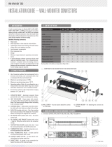
Function of supply air with supply air modules
The conditioned primary air enters through a
variable number of supply air modules below
the trench unit. It escapes through an outlet slot
arranged along the length of the trench unit and
mixes with the secondary air heated or cooled
by the convector before emerging into the room.
Optimum shielding can be provided in front of the
glazing with a slow and low-turbulence leaving
air velocity. The volume of air supplied can be
conveniently adjusted via the variable number of
supply air modules per trench and the continuously
adjustable slider. Up to 60 m³/h of primary air can
be supplied per supply air module. High volumetric
flow combined with low slider position can lead to
noticeable air flow noises (see adjacent diagram).
The designs of Katherm HK with supply air can be
adapted on a project-by-project basis. The trench
widths are then +20 mm larger compared to the
standard widths of Katherm HK models. The trench
heights increase by +35 mm (HK 320) or +20 mm
(HK 290 and HK 360).
Slider positions1)
8. Katherm HK optionally with supply air function
8.1 Katherm HK with supply air modules
Figure Katherm HK with supply air modules
1) The slider position corresponds to the percentage of the open
cross-sectional area of the supply air inlet.
1
1
2
2

17
Katherm HK 1.43
Ready-to-install trench heaters with EC tangential fan
Assembly and installation instructions
Front view of HK 320 (example shows 1 supply air module)
Front view of HK 290 (example shows 2 supply air modules)
Front view of HK 360 (example shows 2 supply air modules)
Top view (view without cover panel)
Side view of HK 320 with supply air
module
Side view of HK 290 with supply air
modules
Side view of HK 360 with supply air
modules
Window side
Window side
Room side
Room side
Katherm HK Unit length
Max. number
of
supply air
modules
[mm]
HK 320
HK 290
915 / 950* 1
1200 2
1700 3
2000 4
2500 5
3000 6
HK 360
950 1
1200 2
1350 2
1850 3
2250 4
Dimensions: Katherm HK with supply air modules
* with Katherm HK 290
Trench length K
Finned convector length K-540

18
1.43 Katherm HK
Ready-to-install trench heaters with EC tangential fan
Assembly and installation instructions
Combination of Katherm HK with supply air trench
(filter optional accessory)
7
6
5
4
2
1
3
8.2 Katherm HK – Supply air ducts ZL
The Katherm supply air trench ZL is available for all
trench heaters (Katherm range). This represents a
400 mm long trench, which can be fitted to all
designs of Katherm units. Treated supply air can
also be fed into rooms through the Katherm supply
air trench ZL. This is achieved with different sizes/
designs of spigots for the most diverse trench
dimensions.
1 Supply air duct with supply air spigots
2 Connecting brackets
3 Supply air slider
4 Reinforcing struts
5 Perforated plate
6 Filter
7 Example of Optiline roll-up grille
Trench
width
Trench
length
Trench
height
Supply air
spigot
Max. air volume
(noiseless)
[mm] [mm] [mm] [mm] [m³/h]
320 400 130 oval
51x128 70
290 400 160 DN 80 60
360 400 210 DN 100 85
Supply air duct, oval, for Katherm HK 320/130 Side view
Side view
Side view
Supply air duct DN 80 for Katherm HK 290/160
Supply air duct DN 100 for Katherm HK 360/210
Adjusting the slider positions
The supply air model, like all standard Katherm units, is
adjusted in height via the adjustment screws and fixed to
the floor via the adjustment feet. To set the desired flow rate
at the supply air module, you can move the slider in various
positions. The illustration on the left shows 4 different slider
positions (100%, 75%, 50% and 30% open). They are also
shown in the design diagrams below, where you can read off
the desired pressure losses, sound levels and air flow rates.
Intermediate values can be interpolated.
100% 75% 50% 30%

19
Katherm HK 1.43
Ready-to-install trench heaters with EC tangential fan
Assembly and installation instructions
Design diagrams
Pressure losses
Pressure lossesPressure losses
Primary air volume
Primary air volume
Primary air volume
Slider position 30% open Slider position 50% open
Sound power level 30 dB(A)
Slider position 75% open
Slider position 100% open
Slider position 30% open Slider position 50% open
Sound power level 30 dB(A)
Slider position 75% open
Slider position 100% open
Slider position 30% open Slider position 50% open
Sound power level 30 dB(A)
Slider position 75% open
Slider position 100% open
oval
Pressure losses
Pressure losses
Pressure losses
Primary air volume
Primary air volume
Primary air volume
Slider position 30% open Slider position 50% open
Sound power level 30 dB(A)
Slider position 75% open
Slider position 100% open
Slider position 30% open Slider position 50% open
Sound power level 30 dB(A)
Slider position 75% open
Slider position 100% open
Slider position 30% open Slider position 50% open
Sound power level 30 dB(A)
Slider position 75% open
Slider position 100% open
oval
Pressure lossesPressure losses
Pressure losses
Primary air volume
Primary air volume
Primary air volume
Slider position 30% open Slider position 50% open
Sound power level 30 dB(A)
Slider position 75% open
Slider position 100% open
Slider position 30% open Slider position 50% open
Sound power level 30 dB(A)
Slider position 75% open
Slider position 100% open
Slider position 30% open Slider position 50% open
Sound power level 30 dB(A)
Slider position 75% open
Slider position 100% open
oval
1
Slider position 30% open
2
Slider position 50% open
3
Slider position 75% open
4
Slider position 100% open
5
Sound power level 30 dB(A)
1
Slider position 30% open
2
Slider position 50% open
3
Slider position 75% open
4
Slider position 100% open
5
Sound power level 30 dB(A)
1
Slider position 30% open
2
Slider position 50% open
3
Slider position 75% open
4
Slider position 100% open
5
Sound power level 30 dB(A)
1
1
1
2
2
2
3
3
3
5
5
5
4
4
4

20
1.43 Katherm HK
Ready-to-install trench heaters with EC tangential fan
Assembly and installation instructions
9. Condensation drainage
9.1. General information
A differentiation is made between tow fundamentally different designs
when operation the Katherm HK in cooling mode: dry cooling and wet
cooling, both in 2-pip and 4-pipe mode.
If the Katherm HK trench unit is used to cool room air, condensation can
be produced at certain cooling water temperatures, room temperatures
and room humidity levels. Katherm HK are fitted as standard with a
condensation tray for condensation drainage. The condensation is
collected by the tray underneath the heat exchanger and discharged and
forward to the drain opening for discharge.
The condensation tray is designed in such a way in accordance with
Hygiene Directive VDI 6022 that it can be fully removed to the room side
for complete cleaning.
It is crucial that the prescribed service intervals (see chapter 10 Service)
for the condensation tray and condensation pump (if necessary) are
maintained for correct operation.
Condensation can be drained away in the Katherm HK in two different
ways:
• condensation drainage with a natural gradient
• condensation drainage using the condensation pump kit
To ensure the drainage of condensation from the Katherm HK, the
gradient needs to be at least 2% (according to DIN EN 12056), without
restriction and without rising sections of pipe. Make sure that the
condensation drainage line is laid without kinks. Take into account all
applicable regulations, such as the use of a ball trap, when connecting the
condensation line to the sewer system. Protect the trap from drying out.
Consider the use of water vapour-impermeable insulation depending on
the pipe material used for the condensation drain. You will need to use a
condensation pump should a natural gradient be impossible on site (see
Section 8.3).
Maximum condensation produced per Katherm HK (at 100% fan speed, 2-pipe system)
Air intake 27°C / 48% 30°C / 70 %
Cooling water temperature 6/12°C 7/12°C 8/14°C 6/12°C
Katherm HK Trench length:
[mm] [l/h] [l/h] [l/h] [l/h]
320/130
290/160
915 / 950 0.32 0.30 0.21 1.83
1200 0.50 0.47 0.32 3.01
1700 0.75 0.70 0.47 4.67
2000 0.95 0.88 0.59 6.03
2500 1.17 1.09 0.71 7.61
3000 1.49 1.38 0.89 9.98
/