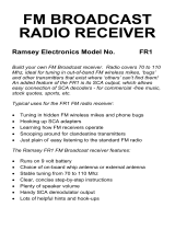
Ramsey Electronics TT1 is a Telephone Recorder (not a phone answering machine) engineered to record both sides of phone conversations. It is voice-activated and offers automatic level control so you no longer need to worry about setting recording levels.
Once connected to a landline phone jack, the TT1 is ready to use right out of the box, no programming required. Nothing to wear out or replace. The TT1 features a simple one-touch record button and an LED to indicate when power is on and while actively recording.
The TT1 uses an endless loop cassette. Any portion of the tape not recorded over is automatically reused. The easy-to-use controls allow you to quickly find specific portions of a recorded conversation using fast forward or rewind with speeds up to 30 times.


-
 1
1
-
 2
2
-
 3
3
-
 4
4
-
 5
5
-
 6
6
-
 7
7
-
 8
8
-
 9
9
-
 10
10
-
 11
11
-
 12
12
-
 13
13
-
 14
14
-
 15
15
-
 16
16
-
 17
17
-
 18
18
-
 19
19
-
 20
20
-
 21
21
-
 22
22
-
 23
23
-
 24
24
-
 25
25
-
 26
26
-
 27
27
-
 28
28


Ramsey Electronics TT1 User manual
- Type
- User manual
- This manual is also suitable for
Ramsey Electronics TT1 is a Telephone Recorder (not a phone answering machine) engineered to record both sides of phone conversations. It is voice-activated and offers automatic level control so you no longer need to worry about setting recording levels.
Once connected to a landline phone jack, the TT1 is ready to use right out of the box, no programming required. Nothing to wear out or replace. The TT1 features a simple one-touch record button and an LED to indicate when power is on and while actively recording.
The TT1 uses an endless loop cassette. Any portion of the tape not recorded over is automatically reused. The easy-to-use controls allow you to quickly find specific portions of a recorded conversation using fast forward or rewind with speeds up to 30 times.
Ask a question and I''ll find the answer in the document
Finding information in a document is now easier with AI
Related papers
-
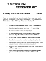 Ramsey Electronics FR146 User manual
-
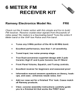 Ramsey Electronics FR6 User manual
-
 Ramsey Electronics FR1 User manual
-
 Ramsey Electronics HR40 User manual
-
 Ramsey Electronics HR20 User manual
-
 Ramsey Electronics TT1 User manual
-
 Ramsey Electronics FT146 User manual
-
 Ramsey Electronics SR2 User manual
-
 Ramsey Electronics QRP-80 User manual
-
 Ramsey Electronics QRP-80 User manual


Other documents
-
Vectronics VEC-131K User manual
-
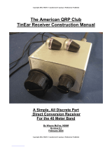 American QRP Club TinEar Construction Manual
-
-
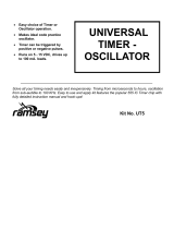 Ramsey UT5 User manual
-
MFJ 9317K Owner's manual
-
ELECRAFT KX1 Owner's manual
-
-
-
-

