Page is loading ...

Ramsey Electronics Model No. SR2
• Enjoy hours of fascinating international listening using just a simple
indoor wire antenna
• Select portions of the 4 to 19.5 MHz shortwave band, easily re-tuned at
any time
• Smooth varactor diode tuning
• Excellent sensitivity and selectivity
• Front panel Volume and Tuning controls
• Multi-stage audio amplifier for room filling volume
• Well designed superhetrodyne circuit is easy to build, makes a nice
one-evening project
• Ideal scout, school, or club project
• Clear, concise step-by-step instructions carefully guide you to a
finished kit that not only works - but you’ll also learn too!
• Runs on a standard 9 volt battery
• Add our matching case and knob set for a finished ‘pro’ look
Have you ever wanted to get into the fascinating world of radio?
The Ramsey SR2 is a fine performer that will bring in the world
using just a few feet of wire as an antenna! Folks of all ages
have successfully built and enjoyed this easy and fun kit.
4-19.5 MHz
SHORTWAVE RADIO

SR2 – 2
PARTIAL LIST OF AVAILABLE KITS
RAMSEY TRANSMITTER KITS
• FM10A FM Stereo Transmitter
• FM100B Professional Synthesized FM Stereo Broadcaster
• FM25B Synthesized FM Stereo Transmitter
• AM25 Synthesized AM Transmitter
• AM1 AM Transmitter
RAMSEY RECEIVER KITS
• FR1 FM Broadcast Receiver
• AR1 Aircraft Band Receiver
• AA7 Active Antenna
• SC1 Shortwave Converter
RAMSEY HOBBY KITS
• SG7 Personal Speed Radar
• SS70A Speech Scrambler
• TT1 Telephone Recorder
• SP1 Speakerphone
• MD3 Microwave Motion Detector
• PH10 Peak hold Meter
• LC1 Inductance-Capacitance Meter
RAMSEY AMATEUR RADIO KITS
• DDF1 DopplerDirection Finder
• HR Series HF All Mode Receivers
• QRP Series HF CW Transmitters
• CPO3 Code Practice Oscillator
• VLF1 Low Bander Low Frequency SWL Converter
• QRP Power Amplifiers
RAMSEY MINI-KITS
Many other kits are available for hobby, school, scouts and just plain FUN. New
kits are always under development. Write or call for our free Ramsey catalog.
4-19.5MHz SHORTWAVE RADIO INSTRUCTION MANUAL
Ramsey Electronics publication No. MSR2 Revision 1.4
First printing: January 2001
COPYRIGHT
2001 by Ramsey Electronics, Inc. 590 Fishers Station Drive, Victor, New York
14564. All rights reserved. No portion of this publication may be copied or duplicated without the
written permission of Ramsey Electronics, Inc. Printed in the United States of America.

SR2 – 3
4-19.5MHz
SHORTWAVE RADIO
Ramsey Publication No. MSR2
Manual Price Only: $5.00
TABLE OF CONTENTS
Introduction to the SR2 ........................................ 4
What You Can Expect to Hear ............................. 4
Shortwave Listening as a Hobby ......................... 5
Circuit Description ................................................ 6
Parts Layout Diagram .......................................... 8
Block Diagram ..................................................... 9
Parts List .............................................................. 10
Assembly Instructions .......................................... 12
Schematic Diagram ............................................. 14
Shortwave Antenna Ideas .................................... 20
Initial Testing and Adjustment ............................. 21
Troubleshooting Tips ........................................... 23
Ramsey Kit Warranty ........................................... 27
KIT ASSEMBLY
AND INSTRUCTION MANUAL FOR

SR2 – 4
INTRODUCTION TO THE SR2
The SR2 is a single-conversion superheterodyne receiver designed
specifically for listening to AM broadcasting stations in the range of 4 to 19.5
MHz. Because of this "superhet" design, your favorite foreign broadcasting
services will come in loud and clear, with pleasing audio sound quality, with
a minimum of overload, frequency drift or heterodyne whistles. Because of
this broadcast oriented design, other shortwave signals such as Morse code
(CW), single-sideband (SSB) voice communications and some Teletype
signals will usually sound like garbled hisses. On the other hand, similarly
inexpensive receivers designed for CW and SSB can give only marginal
performance in receiving broadcast stations due to the lack of
superheterodyne design. For example, our popular Ramsey direct-
conversion receivers for the 40,30 and 20 Meter Amateur bands will also
pick up AM broadcast stations, but you'll mainly hear their strong AM
"carrier" signal due to the lack of the superheterodyne circuitry. Even if such
a carrier is tuned to a "null," listening fidelity is less than desirable.
WHAT YOU CAN EXPECT TO HEAR
First, let's take a look at what is POSSIBLE to hear on your SR2. The
following are the international shortwave broadcasting bands within its
tuning range:
4.750-5.060 MHz. (Lower power, regional "tropical" broadcasting)
5.950-6.200 MHz (Late evening)
7.100-7.300 MHz. (Late afternoon, early evening) (This band is always
shared with the 7.0-7.3 MHz Amateur Radio Band)
9.500-19.500 MHz. (Always "something" on, 24 hours a day!)
Especially strong signals include these, among others:

SR2 – 5
• BBC London: an intelligent perspective on world affairs
• Radio Canada International: editorial quality similar to BBC
• Radio Moscow: powerful signals, increasingly honest and open
• Voice of America: VOA broadcasts are "aimed" outside the USA, but if
you're in the "path" you'll hear it loud and clear!
• U.S. Armed Forces Radio-TV "Feed" Service: Master programming
source for U.S. military radio- hear CBS-NBC-ABC-Mutual news all on
the same "channel," plus many other features and spots which give a
feel for how it's going with those in uniform
• Numerous South American stations
• USA religious broadcasting to other continents
You'll easily tune in broadcasts from many other countries as well. As you
become more and more familiar with the world of shortwave broadcasting,
you'll be deciding on your own favorite band.
You will hear a variety of other "interesting" sounds, but just remember that
this receiver is designed for AM only. If a Morse Code signal really sounds
"good," it is because it is being transmitted in AM tone-modulated form, or
perhaps the signal is so close to an AM broadcast carrier that the carrier
acts as a "beat-frequency-oscillator" (BFO). Even though this receiver can
let you tune through several different HAM radio bands, the signals are not
likely to be intelligible. Reception of CW and SSB signals on an AM receiver
requires a BFO. This is not a complicated feature, but it is beyond the
purpose of the SR2. Our companion receivers designed for the HAM bands
will let you tune into these SSB and CW broadcasts.
SHORTWAVE LISTENING AS A HOBBY
Many people worldwide enjoy listening to shortwave broadcasts of all kinds,
and they keep written records of what they hear. Almost every nation on
earth has some sort of shortwave broadcast service, though many are
much more challenging to tune than the powerful signals of Radio Moscow
and the BBC. In addition, these "SWLs" (Shortwave Listeners) listen to HAM
operators, government and commercial stations and even clandestine
operations. Some shortwave listeners enjoy collecting QSL cards from
stations which they have logged. Shortwave listening is, for some, a step
toward getting a HAM radio license. For others, it is a great hobby in itself.
The SR2 Shortwave Receiver is a good introductory receiver for this hobby.
After you decide exactly what kinds of listening are of the most interest to

SR2 – 6
you, you'll be in a better position to choose a more elaborate receiver. While
there are various multi-band portable radios available, you can expect to pay
at least $100 for a receiver offering a significant improvement over your
trusty SR2.
To learn more about this SWL hobby, look for a copy of "Popular
Communications" at newsstands. An inexpensive and interesting general
introduction to all kinds of radio listening is the book, "Shortwave Listening
Guide" by William Barded, Jr. (1987; Radio Shack Catalog Number 62-
1084). This book also includes helpful introductory information about VHF
monitoring, which you can enjoy with the Ramsey FR-146 and AR-1 receiver
kits, as well as HAM radio, CB, antennas, and other topics.
To learn more about Ramsey Electronics HAM radio kits, write for our
complete catalog. (And, be sure to tell us how you're doing with your SR2
Receiver!) To learn more about the hobby of HAM radio, write ARRL
(American Radio Relay League), 225 Main Street, Newington, CT 06111 or
visit their website: http://www.arrl.org/.
CIRCUIT DESCRIPTION
The following paragraphs describe the circuit operation of the SR-2
Shortwave Receiver kit. Through the use of a simplified block diagram the
basic circuit theory is easy to understand. The full schematic (pg. 14) shows
the details concerning specific operation and component variable
configurations.
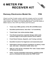
Take a moment and examine the circuit block diagram found on page 9. The
simplified signal flow of the block diagram shows the basic sections of the
receiver. The corresponding components are noted under each main block
and can be cross referenced to the schematic
The start of our circuit begins with the Antenna. RF Signals (Fc = carrier
frequency) from the Antenna are applied to the RF Input and Filtering
allowing only the signals of interest to pass through. The high pass filter
helps eliminate unwanted signals picked up by the antenna improving the
overall reception quality of the radio.
After the input signal is filtered, it moves to the Mixer stage. Notice on the
diagram that there are two inputs to the mixer. We have discussed one of
these input signals coming into the mixer but not the other as of yet. Drop
down to the Local Oscillator block. The local oscillator (LO for short) acts as
your tuning control for what frequencies you can receive by generating a
signal on the board close in value to that which will be used by the mixer.
There is a direct relationship between the generated frequency of the local
oscillator (LO) and the exact receive frequency (Fc) you want to listen to.
This will become clear when we finish discussing the block diagram.
The LO section is a Colpitts oscillator that takes advantage of smooth

SR2 – 7
varactor diode tuning. The varactor (D3) forms an L/C (Inductor/Capacitor)
tank circuit with T3. Increasing the voltage on the varactor diode with R21
(Tuning Pot) increases the capacitance of D3 thus increasing the frequency
output of the LO section.
Now that we know the two signals coming into the Mixer stage, both the Fc
(receive carrier frequency) and the LO (generated local oscillator), we can
better cover its operation. The mixer takes these input signals and performs
a few very basic operations. The technical explanation of how the mixer
combines these signals through Fourier Series is interesting but very drawn
out. The point of using the block diagram, however, is to simplify matters.
Therefore, the function of the mixer is to obtain the ‘product’ and the ‘sum’ of
the input signals. This means you take the input signals and merely ‘add’
and ‘subtract’ their values to determine what you get on the output. The
general formulas to use are quite simply, ‘Fc + LO = Mixer Output’ and ‘Fc –
LO = Mixer Output’.
The realistic output of the mixer stage unfortunately has other signals
besides the ones we want. This brings us to the next stage, Intermediate
Frequency Filtering. An Intermediate Frequency (IF) is a signal somewhere
between the RF signal Fc we started with and the final audio message we
are trying to get. The desired IF we are dealing with is a fixed number, such
as 455 kHz. As long as the proper relationship between Fc and the LO
exists, the IF value will stay constant. Due to the fact that the IF frequency
stays the same all the time, the Intermediate Frequency Filter can be very
narrow. The filter will remove any other signals coming from the mixer that
are not in the proper pass band and yield a clean signal for further
processing.
The next stage is an Amplifier with an adjustable gain feedback loop. The
gain control is dependant on the amount of signal being received (this
Automatic Gain Control ‘AGC’ will be covered in a moment). The amplifier
boosts the signal level of the incoming IF and gives us a stronger signal to
work with.
After the amplifier stage is another Intermediate Frequency Filter. This helps
remove any unwanted residual signals still present and cleans up the
amplified IF for a high quality signal.
At this point the audio signal we are trying to obtain is riding on the IF signal.
The Demodulator circuit finally extracts the message from the IF through a
process called envelope detection. Now that we have our message back in
the audio realm, it is directed through the audio circuitry to the speaker
output.
Wait, there are still a few sections we have not discussed!
The demodulated audio branches off before the audio circuitry and is used
to perform some useful functions. The RSSI LED, Received Signal Strength
Indicator Light Emitting Diode, gives us a general signal level feature. The
stronger the signal we receive, the brighter the LED will glow. This is great
for help pulling in those weak transglobal transmitter signals. The gain of the

SR2 – 8
RSSI circuit is controlled by the value the feedback resistor R17. If you are
commonly using a small antenna and listening to weak signals, increase the
value of R17 to customize the response indication of D2, the signal strength
LED.
The final stage, and the real secret to the sensitivity of the receiver, is the
Automatic Gain Control (AGC). The gain control looks at the amount of
signal level present at the output of the demodulator and varies the amount
of gain the Amplifier has accordingly. If there is a strong signal coming
through the demodulator the AGC circuit lowers the gain of the amplifier. If
the receive signal coming through the demodulator is very weak, the AGC
circuit increases the gain of the amplifier (Q2) allowing us to receive signals
from around the world and listen to them with clarity.
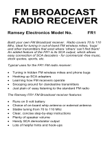
SR2 PARTS LAYOUT DIAGRAM

SR2 – 9
Antenna
J1
RF Input
&
Filtering
Mixer
Interm ediate
Frequency
Filter
Amp
Interm ediate
Frequency
Filter
Audio
(Speaker)
SR-2 Block Diagram
Local
Oscillator
AGC
Demod
Signal
Strength
LED
Automatic Gain Control
Receive Signal
Strength Indicator
C1,C2,C3
L1,L2
Q1
T3,D3,Q3
C15,C16
R21
T1
Q2
T2
D1
U2, J2
U1:A
D2
RSSI
U1:B

SR2 – 10
PARTS LIST
CAPACITORS
1 10 pF ceramic disc capacitor [marked 10] (C30)
1 47 pF ceramic disc capacitor [marked 47] (C15*)
4 100 pF disc capacitor [marked 100, 101, or 100K] (C5,15*,16*,17)
1 330pF disc capacitor [marked 330 or 331] (C2)
6 .001µF disc capacitors [marked .001, 102, or 1nF]
(C1,3,16*,20,21,25)
1 .0039 uF disc capacitor [marked 392 or 392K] (C31)
4 .01µF disc capacitors [marked .01, 103, or 10nF] (C4,6,8,28)
6 .1µF ceramic disc capacitor [marked .1 or 104] (C7,10,12,18,19,29)
2 1µF electrolytic capacitors (C9,24)
3 10µF electrolytic capacitors (C11,22,23)
2 220µF electrolytic capacitors (C13,14)
1 1000 µF electrolytic capacitor (C26)
INDUCTORS
2 1 µH inductors [looks like a resistor with brown-black-gold bands]
(L1,L2)
1 12 µH inductor [looks like a resistor with brown-red-black bands]
(L3)
2 Shielded can inductors [marked 42IF-103] (T1,2)
1 Shielded can inductors [marked 42IF-123] (T3)
RESISTORS
1 2 ohm [red-black-gold] (R15)
1 100 ohm [brown-black-brown] (R26)
3 270 ohm [red-violet-brown] (R16,22,25)
8 1K ohm [brown-black-red] (R3,7,9,10,13,17,18,24)
5 10K ohm [brown-black-orange] (R6,8,11,19,23)
2 22K ohm [red-red-orange] (R2,4)
3 100K ohm [brown-black-yellow] (R1,5,20)
1 1M ohm [brown-black-green] (R12)
SEMICONDUCTORS
1 Red LED (D2)
1 1N270 diode, glass bead style (D1)
1 Varactor diode, transistor style body with two leads (MVAM108) (D3)
3 NPN transistors, 2N3904 or similar (Q1,2,3)
1 LM358 8-pin DIP IC (U1)
1 LM386 8-pin DIP IC (U2)

SR2 – 11
HARDWARE AND MISCELLANEOUS
1 SR2 printed circuit board
2 10K potentiometers (R14,21)
1 DPDT PC-mount push button switch (S1)
1 RCA-type PC-mount jack (J1)
1 Subminiature phone jack (J2)
1 9-volt battery snap connector
1 9-volt battery hold-down clamp
REQUIRED, NOT SUPPLIED:
9-volt alkaline or heavy-duty battery
Earphone, small speaker, or external amplifier with speaker
Antenna or suitable cable, connector, grounding
OPTIONAL
Ramsey SR2 case and knob set (CSR), or your own enclosure

SR2 – 12
ASSEMBLY INSTRUCTIONS
In ALL PC-board assembly steps, our word "INSTALL" means to do this:
Insert the part, oriented or "pointed" correctly, into its holes in the PC
board.
If helpful, gently BEND the part's wire leads or tabs to hold it in place,
with the body of the part snugly against the top side ("component side")
of the circuit board.
Solder ALL wires or pins of the part.
Trim or "nip" all excess wire lengths extending beyond each solder
connection, taking care that wire trimmings do not become lodged in
solder connections.
You can see that this circuit board, the center portion in particular, is fairly
well-filled with components. There's more to this receiver than the average
beginner's radio or even our popular Amateur Band receivers.
Follow the assembly instructions IN SEQUENCE and check off each step as
understood and completed. Some of the components require modification!
Examine the schematic circuit diagram and PC Board parts layout diagram
as you proceed.
Use good soldering techniques! Let your soldering iron tip heat both the
component lead wire and PC board trace enough so that the wire itself AND
the foil trace BOTH become hot enough TOGETHER to melt a bit of solder
so that it flows smoothly from the pin to the PC board trace.
Enough said... Let’s get building!
1. Install S1, the DPDT push button switch. Ensure that the white
plastic switch extends out over the edge of the PC board and that the
switch is flush to the board. Solder all six pins.
2. Install one of the 10K PC mount potentiometers, R14. Be sure it is
seated flush to the PC board, then solder all 5 pins.
3. Install the other 10K PC mount pot, R21. Take care to seat it
properly before soldering the 5 pins.
4. Install J1, the RCA jack. You will want to check your placement
before soldering and be sure to solder all 4 tabs.

SR2 – 13
We will now begin constructing the local oscillator section.
5. Install C22, one of the 10µF electrolytic capacitors. Electrolytic
capacitors have a right and wrong way to be installed. Usually,
capacitors have a wide stripe which indicates their negative lead and the
PC board or Parts Layout Diagram will show the positive side of the
capacitor's installation hole. Be sure to place the ( + ) capacitor lead
into the PC board ( + ) hole and the ( - ) lead into the ( - ) hole before
soldering.
6. Install D3, the varactor diode, marked MVAM108. This part looks
like a transistor except that it only has two leads. It must be installed
with the proper polarity to work correctly. You will note that it has a flat
side. Be sure to look at the PC board silkscreen or parts layout diagram
for proper placement of the flat side. Once you have correctly placed
the part, solder the leads.
7. Install R23, 10K ohm [brown-black-orange].
8. Install Q3, an NPN transistor, [marked 2N3904]. This part is also
oriented by the flat side so check your parts layout diagram for proper
placement. Bend the center lead out until it fits in the board and seat
the part as close to the PC board as possible. Solder all three leads.
9. Install C17, a 100 pF capacitor [marked 100, 101, or 100K].
10. Install C25, .001µF disc capacitor [marked .001, 102, or 1nF].
11. Install C19, a .1µF ceramic disc capacitor [marked .1 or 104].
12. Install C18, another .1µF ceramic disc capacitor [marked .1 or 104].
13. Install R20, 100K ohms [brown-black-yellow].
14. Install R25, a 270 ohm resistor [red-violet-brown].
15. Install R19, 10K ohms [brown-black-orange].
16. Install R24, 1K ohms [brown-black-red].
17. Install C26, the 1000µF electrolytic capacitor. Remember to check
the polarity and install properly before soldering.
18. Install R22, 270 ohms [red-violet-brown].
19. Install C20, .001µF disc capacitor [marked .001, 102, or 1nF].
20. Install C21, another .001µF disc capacitor [marked .001, 102, or
1nF].
Before installing T3, the shielded can inductor [marked 42IF123] we must
make a modification to the part. It's time for a little "destruction"! (If you

SR2 – 14

SR2 – 15

SR2 – 16
jumped ahead and installed T3, we've got bad news for you). Before this
shielded transformer can be installed, its internal capacitor needs to be
removed. Looking at the underside of this transformer, you'll see a tubular
part, probably white with a brown band, somewhat like the resistors in this
kit. This is brittle and easily crushed with any sharp object that can be
pressed against it with mild force (small nail, nutpick, small screwdriver).
You'll find this capacitor will easily disintegrate into particles. DO NOT crush
the capacitors in the other two inductors!
21. After crushing the internal capacitor, install T3. The part fits in the
board only one way. Solder all pins.
That completes assembly of the local oscillator section except for two parts.
You may notice that we skipped over C15 and C16 while installing the other
parts in the area. The reason is that you will have to decide the frequency
range you’re trying to receive to know what value capacitors to install. We’ll
leave that until the end of the assembly process.
We’ll now move on to the RF section of your SR2 kit. The next few parts
form an input filter and mixer section, to combine the RF input with the L.O.
section just built. The output of the mixer is the IF, from which we’ll extract
the final audio. But let’s not get ahead of ourselves.
22. Install L1, 1µH inductor [looks like a fat resistor with brown-black-
gold bands].
23. Install L2, the other 1µH inductor [looks like a fat resistor with
brown-black-gold bands].
24. Install C3, .001µF disc capacitor [marked .001, 102, or 1nF].
25. Install C2, 330 pF disc capacitor [marked 330 or 331].
26. Install C1, .001µF disc capacitor [marked .001, 102, or 1nF].
27. Install R13, 1K ohms [brown-black-red]. R13 isn’t part of the RF
section but is easier to install now, while we’re in the area.
28. Install R3, 1K ohm [brown-black-red]. Watch that third color band
as red is easily confused with orange!
29. Install Q1, another of the NPN transistors [marked 3904]. Observe
correct orientation of the flat side when placing this part.
30. Install C10, .1µF ceramic disc capacitor [marked .1 or 104].
31. Install R12, 1M ohm [brown-black-green]. C10 and R12 are part of
the bias circuit for the audio amplifier, U1. Like R13, it is easier to install
these parts now.
32. Install C30, 10pF [marked 10].

SR2 – 17
33. Install R2, 22K ohms [red-red-orange].
34. Install R1, 100K ohms [brown-black-yellow].
35. Install C24, 1µF electrolytic capacitor. Remember to watch polarity
when installing.
36. Install C5, 100 pF disc capacitor [marked 100, 101, or 100K].
37. Install C4, .01µF disc capacitor [marked .01, 103, or 10nF].
38. Install R26, 100 ohms [brown-black-brown].
39. Install C23, 10 µF electrolytic. Remember to check the polarity
before installing.
40. Install Q2, the last 3904 transistor. Check the parts placement
diagram for correct orientation, then install and solder the three leads.
41. Install C6, .01µF disc capacitor [marked .01, 103, or 10nF].
42. Install R4, 22K ohm [red-red-orange].
43. Install T1, one of the shielded can inductors [marked 42IF-103].
44. Install R5, 100K ohm [brown-black-yellow].
45. Install R6, 10K ohm [brown-black-orange].
46. Install C28, .01µF disc capacitor [marked .01, 103, or 10nF].
47. Install C7, .1µF ceramic disc capacitor [marked .1 or 104].
48. Install R7, 1K ohm [brown-black-red].
49. Install C31, .0039 uF disc capacitor [marked 392 or 392K].
50. Install R8, 10K ohm [brown-black-orange].
51. Install C8, .01µF disc capacitor [marked .01, 103, or 10nF].
52. Install D1, 1N270 glass bead style diode. The banded end (cathode)
MUST be oriented as shown on parts layout.
53. Install R11, 10K ohm [brown-black-orange].
54. Install R10, 1K ohm [brown-black-red].
55. Install R9, 1K ohm [brown-black-red].
56. Install T2, the other shielded can inductors [marked 42IF-103].
57. Install L3, 12 µH inductor [looks like a fat resistor with brown-red-
black bands].

SR2 – 18
58. Install C9, 1µF electrolytic capacitor. Check polarity when installing.
59. Install C11, 10 µF electrolytic. Observe correct polarity before
installing.
60. Install R16, 270 ohm [red-violet-brown].
PROGRESS SUMMARY
Now is a good time to take a break. Examine your work so far checking
things such as component values, parts placement, and solder connections.
Remember the old adage “The bigger the glob the better the job” does not
hold true with RF electronics!
To this point, we have assembled a majority of the receiver. The RF, LO, IF
and Demodulator sections have been built leaving us with the final audio
stage, RSSI circuit, and AGC circuit. Sound like a lot more work? Not at all;
we are going to take advantage of today’s power packed ICs! The LM386
audio chip takes care of our audio needs while the LM358 opamp is used
two-fold in the RSSI and AGC circuits!
61. Install C29, .1µF ceramic disc capacitor [marked .1 or 104].
62. Install U1, the LM358 8 pin IC. Do not confuse it with the other IC;
read the chip marking carefully. You will notice a notch, band or dot on
one end of the IC. This should be oriented as shown on the parts layout
diagram and PC board silkscreen. Be sure the part is seated close to
the PC board before soldering all 8 pins.
63. Install R17, 1K ohm [brown-black-red].
64. Install R18, also 1K ohm [brown-black-red]..
65. Install J2, the subminiature speaker-headphone jack.
66. Install C12, .1µF ceramic disc capacitor [marked .1 or 104].
67. Install R15, 2 ohms [red-black-gold].
68. Next, install U2, the LM386 audio amplifier IC. As with U1, orient
the notched or dotted end as shown in the parts layout diagram and on
the PC board silkscreen. Solder all 8 pins.
69. Install C14, 220µF electrolytic capacitor. The positive lead of the
capacitor must be placed in the hole next to the ( + ) sign.In the same
way,
70. Install C13, placing the positive lead in the correct PC board hole.
Remember, the banded side indicates the negative lead.
• 71. Install the 9-volt battery snap connector, making
sure that the red ( + ) black ( - ) leads are inserted correctly.

SR2 – 19
72. Install the battery clamp. Position battery and holder so as not to
cover nearby PC board mounting holes. Use the method for securing the
clamp that is most convenient for you, such as:
• wire looped through clamp and PC board holes, soldered.
• small screws
• double-faced adhesive strips
• hot-melt glue
73. If you desire increased audio output, C27, 10 µF, may be installed.
Be sure the (+) and (-) leads are inserted correctly.
74. We’re at the end now, just one part left to install. Install D2, the red
LED signal indicator. The short lead is the cathode; it goes toward
potentiometer R21. Leave it standing about 1/2 an inch off of the board
when soldering. After soldering bend it over to a 90º angle at its midpoint
so that it faces the outside of the board.
Your shortwave broadcast receiver is now finished, except for the capacitors
that will determine the frequency range you will receive.
SHORTWAVE ANTENNA IDEAS
The type of antenna you'll want to use for your SR2 depends on the degree
of interest you have in shortwave listening, whether you are limited to an
indoor or balcony antenna, and whether you think you may soon want to
obtain a HAM radio license. If the latter is true, you may want to consult
HAM radio literature and build the dipole or vertical antenna which you also
plan to use for HAM listening and transmitting. A 40-meter (7 MHz) antenna
is quite nice for the tuning range of the SR2.
The rest of these notes on antennas are for the benefit of SR2 builders who
simply wish to enjoy some shortwave broadcast listening. The SR2 is very
sensitive, so its antenna requirements are minimal for casual evening
listening when international broadcast signals are quite strong. 10 to 20 feet
of insulated hookup wire can be neatly strung behind furniture and curtains
for an adequate indoor antenna. The same length of wire, or more, outdoors
or up in the attic, will be an even better receiving antenna.
1. The ideal antenna setup for this frequency range is considered to be an
outdoor wire 25 to 50 feet in length, with the ground side of the
antenna jack connected to a copper cold water pipe.
2. For convenience, a short length of audio cable with pre-wired RCA plug is
adequate for making antenna and ground connections. (RF coaxial
cable is not essential for this application).
3. A "banana plug" may also be plugged into the antenna jack but will not

SR2 – 20
provide a ground connection.
4. If an indoor antenna is necessary, simply make it as long as possible and
as high up from concrete floors as you can.
5. When installing any outdoor antenna, BE VERY CAREFUL not to let your
antenna wire come in contact with electric power lines.
6. Any antenna wire for shortwave listening may run horizontally, vertically
or some both ways, or at an angle!
7. If you have a roof-mounted TV antenna, its feedline will make a great
antenna for your SR2.
8. Some existing objects such as; metal downspouts, gutters, windows, door
screens, or attic insulation foil can serve as antennas!
If you are completely restricted to indoor antennas, you will enjoy the extra
boost of the Ramsey Active Antenna Kit, model AA-7. Its built-in whip
antenna can also be boosted by your simple indoor wire antenna, and the
AA-7 may be used with any receiver or even a VHF scanner. It's easy to
build and a nice companion for your SR2. If you need more construction
details on antennas, check the book mentioned on page 6, or any
introductory HAM radio book, or the Radio Shack book on Antennas (No.
62-1083).
75. Decide what frequency range you would like to receive and select
the values for C15 and C16 from the chart. A suggested configuration
would be C15 = 47 pF and C16 = 100 pF. This will give you complete
coverage from 6 to 11 MHz by adjusting T3 in or out. This is a very
active section of the Shortwave Band and will provide you with hours of
listening enjoyment any time of the day. Select and install C15 and C16.
INITIAL TESTING AND ADJUSTMENT
Before turning on your receiver, please double check the following:
correct orientation of all IC's.
correct orientation of flat side of all transistors.
correct orientation of the diodes.
correct polarity of all electrolytic capacitors.
1. Connect a speaker or earphones and antenna.
2. Install a fresh 9-volt alkaline battery.
3. Set both potentiometer controls to their middle positions.
/