Page is loading ...

Visit www.trailfx.com or 1 (866) 638-4870 for Warranty Information / Tech Support / Product Updates
.
2021 Keystone Automotive Operations Inc. All Rights Reserved. 03/04/2022-R01 Page-1-11
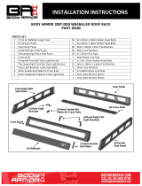
APPLICATION: 1999-2014 Ford Econoline Full Size Van
Assembly, Installation, Operation and
Maintenance Instructions
Running Board
Part Number:
RBV03B
60 - 180 minutes
Dealer / Installer: Provide a copy of these instructions to the end user of this product. These instructions
provide important operating and safety information for proper usage of this product.
Demonstrate the proper use of the product with the end user. Have the end user
demonstrate that they understand the proper use of the product.
End User: Read and follow all instructions included in this manual. Ask your Dealer / Installer for
assistance if you do not understand the proper use of the product. Never remove any
decals from the product. Failure to follow these instructions can result in injury or death.
WARNING
PARTS LIST
Qty Part Description Qty Part Description
1 Driver/Left Side Running Board 2 10mm Lock Washers
1 Passenger/Right Side Running Board 2 10mm Hex Nuts
1 Driver/Left Side Front Bracket 1 8mm Insert Tool
1 Driver/Left Side Rear Bracket 3 8-1.25mm Inserts
1 Passenger/Right Side Front Bracket 10 8-1.25mm Clip-Nuts
1 Passenger/Right Side Center #2 Bracket 1 8-1.25mm x 40mm Hex Bolt
1 Passenger/Right Side Center #3 Bracket 10 8-1.25mm x 25mm Hex Bolts
1 Passenger/Right Side Center #4 Bracket 11 8mm x 24mm x 2mm Flat Washers
1 Passenger/Right Side Rear #5 Bracket 10 8mm Lock Washers
2 12-1.75mm x 40mm Bolt Plates 1 8mm Hex Nut
2 10-1.5mm x 35mm Bolt Plates 7 6mm Double Bolt Plates
2 12mm x 32mm OD x 3mm Flat Washers 14 6mm x 22mm OD x 2mm Flat Washers
2 12mm Lock Washers 14 6mm Lock Washers
2 12mm Hex Nuts 14 6mm Hex Nuts
2 10mm x 30mm OD x 2.5mm Flat Washers
TORQUE SPECIFICATION
Size Torque Size Torque
12 MM 70 ft/lbs 8 mm 20 ft/lbs
10 MM 34.5 ft/lbs 6 MM 102 in/lbs

Visit www.trailfx.com or 1 (866) 638-4870 for Warranty Information / Tech Support / Product Updates
.
2021 Keystone Automotive Operations Inc. All Rights Reserved. 03/04/2022-R01 Page-2-11
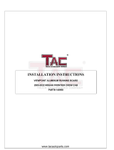
(2) Passenger/right #4
and #5 (same) rear
Mounting Brackets
Driver/left rear
Mounting Bracket
Driver/left front
Mounting Bracket
Passenger/right front
Mounting Bracket
Passenger/right #2
Mounting Bracket
Passenger/right #3
Mounting Bracket
INSTALLATION PROCEDURE:
REMOVE CONTENTS FROM BOX. VERIFY ALL PARTS ARE PRESENT. READ INSTRUCTIONS CAREFULLY BEFORE
STARTING INSTALLATION. DRILLING IS REQUIRED ON 99-03 MODELS. MINOR DRILLING MAY BE REQUIRED ON
ALL MODELS IF BODY PANELS DO NOT LINE UP PROPERLY.
1. Start the installation under the driver side of the vehicle. Locate and remove the rubber plug near the front tire opening,
(Figure 1). Select (1) 10mm Bolt Plate, (Figure 2). Insert the Bolt Plate into and across the opening, (Figures 3 and 13).
2. Select the driver side front Mounting Bracket, (Figure 4). Attach the Bracket to the Bolt Plate with (1) 10mm Flat Washer,
(1) 10mm Lock Washer and (1) 10mm Hex Nut, (Figure 5). Leave hardware loose.
3. Line up the mounting tab on the Bracket with the factory hole in the pinch weld. Slide (1) 8mm Clip Nut over the hole in the
pinch weld with the nut toward the outside of the vehicle, (Figure 3).
IMPORTANT: On some model/years, 5/16” holes will need to be drilled through the pinch weld to attach the tab on the
Mounting Bracket to the pinch weld.
a. Line up the tab on the Bracket with a flat area on the back of the pinch weld.
b. Fully tighten the 10mm Hex Nut on the Bolt Plate. Use the tab on the Bracket for a guide and drill a 5/16” hole
through the tab and the pinch weld.
IMPORTANT! Any cutting or drilling tool may break or shatter. Government regulations require safety glasses & equipment at
all times when cutting or drilling.
c. Slide (1) 8mm Clip Nut over the hole in the pinch weld with the nut toward the outside.
4. Attach the mounting tab on the Bracket to the 8mm Clip Nut with (1) 8mm x 25mm Hex Bolt, (1) 8mm Lock Washer and (1)
8mm Flat Washer, (Figure 5). Snug but do not fully tighten the hardware.
5. Move along the bottom of the body to the rear bracket location, (Figure 7). Locate and remove the large oval rubber plug.
Insert (1) 12mm Bolt Plate into the opening, (Figures 6 & 7)
6. Attach the driver side rear Bracket to the Bolt Plate with (1) 12mm Flat Washer, (1) 12mm Lock Washer and (1) 12mm Hex
Nut, (Figures 8 & 9). Repeat the appropriate Steps 3 & 4 to attach the mounting tab on the Bracket to the back of the pinch
weld.

Visit www.trailfx.com or 1 (866) 638-4870 for Warranty Information / Tech Support / Product Updates
.
2021 Keystone Automotive Operations Inc. All Rights Reserved. 03/04/2022-R01 Page-3-11
7. Select the short driver/left Running Board. Place the Running Board on top of the Brackets. Locate the channels in the
bottom of the Running Board. Select (2) 6mm Double Bolt Plates, (Figure 10). Insert the Bolt Plates into the channels in the
bottom of the Running Board closest to the Brackets, (Figure 11). Lift the Running Board up and guide the studs down through
the Brackets. Attach the Running Board to the Brackets with (4) 6mm Flat Washers, (4) 6mm Lock Washers and (4) 6mm Hex
Nuts, (Figure 12). NOTE: The Running Board is designed to fit close to the vehicle. It may be necessary to loosen the Bracket
hardware and tilt the Brackets downward to insert the Running Board between the Brackets and the body. Do not tighten
hardware at this time.
8. Level and adjust the Running Board forward or backward as desired and fully tighten all hardware. NOTE: Typical installation
is with front of Board 2-3” back from front tire opening.
9. Move to the passenger side of the vehicle. Locate the rubber plug near the front tire opening, (Figure 13). Repeat Steps 1-4
to install the passenger side Front Bracket, (Figures 14 & 15)
10. Continue along the body to the #2 Mounting Bracket location, (Figure 16). Repeat Steps 5 & 6 to install the passenger side
#2 Bracket, (Figures 17 & 18)
11. Move along the body to the #3 Bracket location below the side door, (Figures 19 & 27). Determine the correct procedure for
your year/model for the remaining (3) passenger side Brackets:
Models with factory holes in pinch weld and inner body panel:
a. Locate the factory hole in the pinch weld. Also locate the square hole and small round hole in the inner body panel near and
above the hole in the pinch weld, (Figure 19). NOTE: Hold the appropriate Mounting Bracket up in each location to help
determine the correct holes to use.
b. Slide (1) 8mm Clip Nut into the square hole and in line with the smaller round hole. Next, slide (1) 8mm Clip Nut over the
hole through the pinch weld as described in Step 3, (Figure 19).
c. Select the passenger side #3 Mounting Bracket, (Figure 20). Attach the Bracket to the (2) Clip Nuts with (2) 8mm x 25mm
Hex Bolts, (2) 8mm Lock Washers and (2) 8mm Flat Washers, (Figure 21). Do not fully tighten hardware at this time.
d. Repeat Steps a—c to install the #4, (Figure 22—24), and #5 rear, (Figure 25), Brackets, (#4 and #5 locations use the
same Bracket).
e. Skip to Step 12.
Models without factory holes in the pinch weld and/or inner body panel:
a. Repeat Step 7 to attach the Running Board to the front and #2 Mounting Brackets, (Figure 26).
b. Use a stand or a jack to hold the Running Board up and level with the front (2) Brackets.
c. Select the #3 passenger side Bracket, (Figure 20). With the Running Board level to the vehicle, hold the Bracket up in
position against the back of the pinch weld and body panel. Mark the location of the slots in the Bracket onto the sheet
metal, (Figure 27). NOTE: Use a clamp or locking pliers to temporarily attach the Bracket to the pinch weld.
d. Drill a 7/16” hole in the center of the mark for the top mounting tab. IMPORTANT: Make sure the Running Board is level to
the vehicle before drilling any mounting holes.
e. Select the 8mm Threaded Insert Tool, (1) 8mm x 40mm Hex Bolt, (1) 8mm Flat Washer and (1) 8mm Threaded Insert.
Assemble the Insert as pictured in Figure 30.
f. Firmly hold the handle and push the Insert into the hole. Use a small hammer to gently tap the insert into the hole if
necessary. Once inserted, hold the handle with one hand and turn the 8mm Hex Bolt, (tighten), with a wrench to expand the
insert in the body panel. Continue to tighten the hex bolt until the insert is fully compressed and close to flush with the
surface. Remove bolt and tool from the insert, (Figure 31). WARNING: Do not overtighten the hex bolt or the insert may
become damaged.
g. Repeat Step 3 to drill the 5/16” hole through the pinch weld as needed.
h. Select the passenger side #3 Mounting Bracket. Attach the Bracket to the Insert and Clip Nut with (2) 8mm x 25mm Hex
Bolts, (2) 8mm Lock Washers and (2) 8mm Flat Washers, (Figure 21). Do not fully tighten hardware at this time.
i. Repeat Steps a—h to install the identical #4 and #5 Brackets, (Figures 23, 24, 28, 29 and 33).

Visit www.trailfx.com or 1 (866) 638-4870 for Warranty Information / Tech Support / Product Updates
.
2021 Keystone Automotive Operations Inc. All Rights Reserved. 03/04/2022-R01 Page-4-11
12. Select the long passenger side Running Board. Place the Running Board on top of the (5) Brackets. Locate the channels in
the bottom of the Running Board. Select (5) 6mm Double Bolt Plates, (Figure 10). Insert the Bolt Plates into the channels in the
bottom of the Running Board closest to the Brackets, (Figure 11). Attach the Running Board to the Brackets with (10) 6mm Flat
Washers, (10) 6mm Lock Washers and (10) 6mm Hex Nuts, (Figures 32 & 33). Do not tighten hardware at this time.
13. Level and adjust the Running Board forward or backward as desired to match driver side and fully tighten all hardware,
(Step 8).
14. Do periodic inspections to the installation to make sure that all hardware is secure and tight.
To protect your investment, wax this product after installing. Regular waxing is recommended to add a protective layer over the finish. Do
not use any type of polish or wax that may contain abrasives that could damage the finish.
Aluminum polish may be used to polish small scratches and scuffs on the finish. Mild soap may be used also to clean the Running Boards.
INSTALLATION IMAGES:
Driver/Left Side Installation Pictured
(Fig 1) Remove rubber plug from
driver side front mounting location
(Fig 2) 10mm Bolt Plate
Front
10mm Bolt Plate
(Fig 3) Slide 8mm Clip Nut over
factory hole in pinch weld
(Fig 4) Driver/left front Bracket
Front

Visit www.trailfx.com or 1 (866) 638-4870 for Warranty Information / Tech Support / Product Updates
.
2021 Keystone Automotive Operations Inc. All Rights Reserved. 03/04/2022-R01 Page-5-11
INSTALLATION IMAGES CONTINUED:
(Fig 5) Driver/left front Bracket
10mm Flat Washer
10mm Lock Washer
10mm Hex Nut
8mm Hex Bolt
8mm Lock Washer
8mm Flat Washer
Front
IMPORTANT: On some model/years, 5/16” holes
will need to be drilled through the pinch weld to
attach the tab on the Mounting Bracket to the
pinch weld.
Attach the Brackets to the Bolt Plates first,
temporarily install the Running Board, and make
sure Board is level then mark holes before drilling
holes through pinch weld.
Repeat for all Bracket installations
(Fig 6) 12mm Bolt Plate
12mm Bolt Plate
8mm Clip Nut
(Fig 7) Remove rubber plug from
driver side rear mounting location
(Fig 8) Driver/left rear Bracket
Front
Front
(Fig 10) 6mm Double Bolt Plate
Front
(Fig 9) Driver/left side rear Bracket installation
12mm Flat Washer
12mm Lock Washer
12mm Hex Nut
8mm Hex Bolt
8mm Lock Washer
8mm Flat Washer

Visit www.trailfx.com or 1 (866) 638-4870 for Warranty Information / Tech Support / Product Updates
.
2021 Keystone Automotive Operations Inc. All Rights Reserved. 03/04/2022-R01 Page-6-11
INSTALLATION IMAGES CONTINUED:
(Fig 11) Slide 6mm Bolt Plates into
channels on bottom of Board (Fig 12) Attach Running Board to Brackets
Front
(2) 6mm Flat Washers
(2) 6mm Lock Washers
(2) 6mm Hex Nuts
10mm Bolt Plate
Front
(Fig 13) Passenger/right front location
pictured. Slide 8mm Clip Nut over
factory hole in pinch weld
(Fig 14) Passenger/right
front Bracket
Front
Passenger/right side installation pictured
(Fig 15) Passenger/right front Bracket (Fig 16) passenger side #2 mounting location
Front Front
8mm Clip Nut
12mm Bolt Plate
8mm Hex Bolt
8mm Lock Washer
8mm Flat Washer
10mm Flat Washer
10mm Lock Washer
10mm Hex Nut

Visit www.trailfx.com or 1 (866) 638-4870 for Warranty Information / Tech Support / Product Updates
.
2021 Keystone Automotive Operations Inc. All Rights Reserved. 03/04/2022-R01 Page-7-11
INSTALLATION IMAGES CONTINUED:
(Fig 17) Passenger/right #2 Bracket
(Fig 18) Passenger side #2 Bracket
Front
Front
8mm Hex Bolt
8mm Lock Washer
8mm Flat Washer
12mm Flat Washer
12mm Lock Washer
12mm Hex Nut
Front
(Fig 19) Passenger side #3 location
8mm Clip Nut
IMPORTANT: On some model/years, 5/16” holes
will need to be drilled through the pinch weld (see
above) to attach the tab on the Mounting Bracket
to the pinch weld.
Attach the Brackets to the Bolt Plates first,
temporarily install the Running Board, and make
sure Board is level then mark holes before drilling
holes through pinch weld.
Repeat for all Bracket installations
(Fig 20) Passenger
side #3 Bracket
Front
(Fig 21) Passenger side #3 Mounting Bracket
Front
(2) 8mm Hex Bolts
(2) 8mm Lock Washers
(2) 8mm Flat Washers

Visit www.trailfx.com or 1 (866) 638-4870 for Warranty Information / Tech Support / Product Updates
.
2021 Keystone Automotive Operations Inc. All Rights Reserved. 03/04/2022-R01 Page-8-11
INSTALLATION IMAGES CONTINUED:
(Fig 24) Passenger side #4 Bracket
(Fig 22) Passenger side #4 location
(Fig 23) Passenger side #4 Bracket
Rear
Rear
Front
8mm Clip Nut
(2) 8mm Hex Bolts
(2) 8mm Lock Washers
(2) 8mm Flat Washers
(Fig 25) Passenger side #5 (rear) location
Rear
(Fig 26) Passenger/right front and
#2 Bracket installation
Front
(2) 6mm Flat Washer
(2) 6mm Lock Washers
(2) 6mm Hex Nuts
(Fig 27) Passenger side #3 location
Front
Drill 7/16” hole
and Install insert
Drill 5/16” hole
and use Clip Nut

Visit www.trailfx.com or 1 (866) 638-4870 for Warranty Information / Tech Support / Product Updates
.
2021 Keystone Automotive Operations Inc. All Rights Reserved. 03/04/2022-R01 Page-9-11
INSTALLATION IMAGES CONTINUED:
(Fig 28) Passenger side #4 location
Rear
Drill 5/16” hole and
use Clip Nut Drill 7/16” hole and
Install insert
(Fig 29) Passenger side #5 (rear) location
Drill 7/16” hole and
Install insert
Drill 5/16” hole and
use Clip Nut
IMPORTANT: On some model/years, 8mm
Threaded Inserts will need to be installed in
locations indicated by arrows, (Fig 27-29).
Level Running Board. Hold Bracket up in position
against side of body panel.
Mark location of slots onto sheet metal.
Drill (3) 7/16” holes as required for passenger
side #3, #4 and #5 (rear) Brackets only.
Assemble Insert Tool and install Inserts as
described in Steps 11a - i, (Fig 30-31).
(Fig 30) Assemble Insert Tool as
pictured. Turn wrench clockwise
to pull/expand insert in hole
(Fig 31) Example fully installed Insert
(Fig 32) Passenger/right #3 Bracket installation
Rear
(2) 6mm Flat Washer
(2) 6mm Lock Washers
(2) 6mm Hex Nuts
(Fig 33) Passenger/right #4 and #5,
(rear), Bracket installation pictured.
NOTE #4 and #5 Brackets are identical.
Rear
(2) 6mm Flat Washer
(2) 6mm Lock Washers
(2) 6mm Hex Nuts

Visit www.trailfx.com or 1 (866) 638-4870 for Warranty Information / Tech Support / Product Updates
.
2021 Keystone Automotive Operations Inc. All Rights Reserved. 03/04/2022-R01 Page-10-11
Complete Installation - Passenger Side
PRODUCT CARE
• Periodically check the product to ensure all fasteners are tight and components are intact.
• Regular waxing is recommended to protect the finish of the product.
• Use ONLY Non-Abrasive automotive wax. Use of any soap, polish or wax that contains an abrasive is detrimental and can
scratch the finish leading to corrosion.
• Aluminum polish may be used to polish small scratches and scuffs for Stainless Steel finish.
• Mild soap may be used to clean the product for both Stainless Steel and Black finish.
FAQ’s
1. Hardware and mounting brackets are not aligning properly
Ensure that hardware is being used on the correct side of vehicle. In some cases, the hardware may appear same for driver and
passenger side but may alter the alignment of mounting location. Check mounting brackets for both sides.
2. Products are thumping / rattling after Installation
Ensure that all required mounting brackets / hardware’s are installed & tightened correctly.
Suggest using white Lithium / regular grease between metal-to-metal contact.
3. Missing / Excess Hardware
Recheck hardware count as per the part list.
4. Product not installing properly
Ensure the Year / Make / Model as well as cab and bed dimensions are correct for the application. Review all steps for installation to
ensure they were followed correctly.
5. Who should be contacted for questions regarding product / installation assistance?
www.trailfx.com / [email protected] or 1-(866) 638-4870

Visit www.trailfx.com or 1 (866) 638-4870 for Warranty Information / Tech Support / Product Updates
.
2021 Keystone Automotive Operations Inc. All Rights Reserved. 03/04/2022-R01 Page-11-11
Warranty Terms:
3 Year Limited Warranty:
TrailFX and Keystone Automotive Operations Inc. make no guarantees or warranties for products not
manufactured by Keystone Automotive Operations Inc. Such products are covered solely under any
applicable warranty of the manufacturer. It is always recommended that the operating instructions and
warranty instructions provided by the manufacturer are followed.
Keystone Automotive Operations Inc. warrants its products to be free from manufacturing and material
defects to the original purchaser for the length of warranty stated above from the date of retail purchase.
If any products are found to have a manufacturing or material defect, the product will be replaced or
repaired at the option of TrailFX and Keystone Automotive Operations Inc. with proof of purchase by the
original purchaser. The original purchaser shall pay all transportation and shipping costs associated with
the return of the defective product and the defective product shall become the property of Keystone
Automotive Operations Inc.
The Warranty applies to Keystone Automotive Operations Inc. products used for individual and
recreational purposes. Commercial usage of the Keystone Automotive Operations Inc. products limits the
warranty to 90-days from date of purchase.
The Warranty applies only to Keystone Automotive Operations Inc. products which are found to be
defective in manufacturing or material. This warranty does not apply to normal wear and tear of the finish
placed on Keystone Automotive Operations Inc. products.
TrailFX and Keystone Automotive Operations Inc. are not responsible for any labor costs incurred for
removal or replacement of the defective product.
TrailFX and Keystone Automotive Operations Inc. are not responsible for repair or replacement of any
product under the limited warranty where the product was improperly installed, misapplied, altered,
abused, neglected, overloaded, misused or damaged as a result of an accident, including any use of the
product not in accordance with all product operating and safety instructions.
Without limiting the generality of the foregoing, TrailFX and Keystone Automotive
Operations Inc. shall under no circumstances be liable for any incidental or consequential loss or damage
whatsoever arising out of, or in any way relating to any such breach of warranty or claimed defect in, or
non-performance of the products. Some states do not allow the exclusion or limitation of incidental or
consequential damages, so the above exclusion or limitation may not apply to you.
This limited warranty gives you specific legal rights, and you may also have other rights that vary from
state to state.
/