Page is loading ...

Features
General description:
Dual RS-232 port module with port B dedicated for
master clock/master time interface
RS-232 port A is available for connection to printers,
terminals, or other compatible peripherals
Allows the 4100ES Fire Control Panel system time to
be synchronized with the building master time or other
desired compatible time reference
Compatible with 4100U fire alarm control panels
Includes a 4.5 ft (1.4 m) connection cable with DB-25,
RS-232 connector
Master clock interface compatibility:
Connects to master time control centers such as the
model 6400 and 6351 that provide Simplex
®
BCD
(binary coded decimal) time signals to the model
6400-9568 BCD Code Converter**
For extended timekeeping accuracy, the model 6400
or 6351 Time Control Center can be connected to GPS
Time Reference Interface Module GPS/6400**
Compatible with other RS-232 interfaces that accept
and respond to QT (query time) and QD (query date)
requests
Mounting:
Motherboard/daughter card format requires a single
slot and mounts in an expansion bay
Description
Simplex fire alarm control panels maintain time and date
for reference in the history logs. For applications where a
master time control exists in the facility, the 4100-9816
Master Clock Interface Module provides an interface for
coordinating the fire alarm control panel time to that of
the master reference.
When time accuracy requirements include synchronization
to GPS satellite time, the GPS/6400 Interface Module with
the GPS-427A Antenna/Receiver can be connected to the
model 6400 or 6351 Time Control Center.
For additional information, refer to Installation and
Operating Instructions 574-913.
* This product has been approved by the California State Fire Marshal (CSFM) pursuant to
Section 13144.1 of the California Health and Safety Code. See CSFM Listing
7165-0026:251 for allowable values and/or conditions concerning material presented in this
document. It is subject to re-examination, revision, and possible cancellation. Additional
listings may be applicable; contact your local Simplex product supplier for the latest status.
Listings and approvals under Simplex Time Recorder Co. are the property of Tyco Safety
Products Westminster.
** For additional BCD Code Converter information refer to data sheet S6400-0002.
For additional 6400 information, refer to data sheet S6400-0001.
For additional 6351 information, refer to data sheet S6351-0001.
For additional GPS/6400 information refer to data sheet GPS6400BRO1.
6400/6351 Series Time Control
Center with system clocks
10:09:30
time
control
center
GPS/6400 Interface
System Option
6400-9568
Code Converter
Press ACK located under flashing indicator.
Repeat operation until all events are acknowledged.
Local tone will silence.
A B C
AC Power
D E F G H I
J K L M N O P Q R
'SP' ( ) , 0 :
S T U V W X Y Z /
ALARMS
Fire Alarm Priority 2 Alarm
SYSTEM WARNINGS
Supervisory Trouble Alarm Silenced
Emergency Operating Instructions
Alarm or Warning Condition
How to Acknowledge / View Events
How to Silence Building Signals
System indicator flashing. Tone On. Press Alarm Silence.
How to Reset System
Press System Reset.
Press Ack to silence tone device.
ZONE
1
SIG
2
AUX
3
FB
4
IO
5
IDNet
6
P
7
A
8
L
9
NET ADDR
0
DEL
Enter C/Exit
Fire Alarm
Ack
Priority 2
Ack
Supv
Ack
Trouble
Ack
Alarm
Silence
System
Reset
Event
Time
Enable
On
Arm
Disable
Off
Disarm
Auto
Lamp
Test
More
Info
Menu
Previous
Next
4100ES Fire Alarm Control Panel
10:09:30
10:09:30
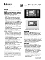
4100-9816 Master
Clock Interface Module
Typical 4100ES Master Clock Interface Block Diagram
Specifications
Standby Current
132 mA @ 24 VDC
Alarm Current
132 mA @ 24 VDC
Operating Temperature
Range
32 F to 120 F (0 C to 49 C)
Humidity Range
Up to 93% RH, non-condensing
@ 90° F (32° C)
Mounting
Single slot motherboard/daughter
card
Connections Provided
DB-25 plugs and terminal blocks
Fire Control Panels
UL, ULC, CSFM Listed; FM Approved; Model 4100-9816 Dual Port RS-232
MEA (NYC) Acceptance* Module with Master Clock Interface
S4100-0033-4

Tyco is a registered trademark of Tyco International Services GmbH and is used under license. Simplex and the Simplex logo are trademarks of Tyco International Ltd. and its
affiliates and are used under license.
Tyco Safety Products Westminster • Westminster, MA • 01441-0001 • USA S4100-0033-4
www.tycosafetyproducts-usa-wm.com
© 2011 Tyco Safety Products Westminster. All rights reserved. All specifications and other information shown were current as of document revision date and are subject to change without notice.
Press ACK located under flashing indicator.
Repeat operation until all events are acknowledged.
Local tone will silence.
A B C
AC Power
D E F G H I
J K L M N O P Q R
'SP' ( ) , 0 :
S T U V W X Y Z /
ALARMS
Fire Alarm Priority 2 Alarm
SYSTEM WARNINGS
Supervisory Trouble Alarm Silenced
Emergency Operating Instructions
Alarm or Wa rning Con dition
How to Acknowledge / View Events
How to Silence Buil ding Signals
System indicator flashing. Tone On. Press Alarm Sil ence.
How to Reset System
Press System Reset.
Press Ack to silence tone device.
ZONE
1
SIG
2
AUX
3
FB
4
IO
5
IDNet
6
P
7
A
8
L
9
NET ADDR
0
DEL
Enter C/Exit
Fire Alarm
Ack
Priority 2
Ack
Supv
Ack
Trouble
Ack
Alarm
Silence
System
Reset
Event
Time
Enable
On
Arm
Disable
Off
Disarm
Auto
Lamp
Test
More
Info
Menu
Previous
Next
4100ES Fire Alarm Control Panel
(Fire Alarm Network compatible)
Panel mounted Master Clock
Interface Module 4100-9816
6400-9568 Code Converter with 6800-9502,
120 VAC Power Supply, required to convert
extended BCD input to RS-232 output
Extended BCD clock time signals
with time and date required, refer
to 6400/6351 Series Time Control
Center documentation for details
Field wiring, 4 wire RS-232 compatible
cable, total connection length not to
exceed 100 ft (30 m) using 18 AWG wire
6400/6351 Series Time Control Center with system clocks
Connection to 6400/6351 Time Control
Center (requires RS-232 Module 6400-9505)
RS-232 Cable assembly with 4.5 ft (1.3 m) leads
(supplied with 4098-9816); junction box by others
10:09:30
10:09:30
GPS/6400 Interface Module Option
GPS-427A
Antenna/Receiver
10:09:30
time
control
center
4100-9816 Master Clock Interface System Reference
/


