Page is loading ...

Features
Remote Annunciator Panels provide fire alarm
control panel status information at locations
distant from the fire alarm control panel
Typical functions include:
Remote status LED indicators and dedicated switch
input controls located on LED/switch modules
Remote status LED indicator modules with 8 red or
16 (8 red/8 yellow) LEDs that are pluggable to allow
color selection (yellow, green, or red LEDs are
ordered separately)
Remote microphone and operator interface for access
to the emergency voice/alarm communications system
Remote master telephone for communicating to the
firefighter telephone system
Also available with InfoAlarm Command Center
expanded content user interface (refer to page 5 and to
data sheet S4100-0045 for additional information)
Additional optional modules include:
Remote Command Center module for LCD status
readout and keyswitch controlled functions
24 Point I/O module
RS-232 ports for remote printer or terminal
connections
Power supplies with battery charger for annunciator
Panel mounted printer for system status recording
Wiring requirements:
RUI or RUI+ (remote unit interface) supervised
communications from the host fire alarm control
panel provide Style 4 or Style 7 SLC (signaling line
circuit) connections
Microphone and telephone circuits require their own
dedicated wiring
Listed to:
UL Std. 864, Fire Detection and Control (UOJZ), and
Smoke Control Service (UUKL)
UL Std. 2017, Process Management Equipment
(QVAX)
UL Std. 1076, Proprietary Alarm Units-Burglar
(APOU)
UL Std. 1730, Smoke Detector Monitor (UULH)
ULC Std. S527-99
* See page 4 for additional listing details. This product has been approved by the California
State Fire Marshal (CSFM) pursuant to Section 13144.1 of the California Health and
Safety Code. See CSFM Listing 7165-0026:0251 for allowable values and/or conditions
concerning material presented in this document. Additional listings may be applicable;
contact your local Simplex
®
product supplier for the latest status. Listings and approvals
under Simplex Time Recorder Co. are the property of Tyco Fire Protection Products.
On
Off
Auto
On
Off
Auto
On
Off
Auto
On
Off
Auto
On
Off
Auto
On
Off
Auto
On
Off
Auto
On
Off
Auto
Press ACK located under flashing indicator.
Repeat operation until all events are acknowledged.
Local tone will silence.
Emergency Operating Instructions
Alarm or Warning ConditionHow to Acknowledge / View Events
How to Silence Building Signals
System indicator flashing. Tone On.
Press Alarm Silence.
How to Reset System
Press System Reset.
Press Ack to silence tone device.
A B C D E F G H I
J K L M N O P Q R
'SP' ( ) , # :
S T U V W X Y Z /
ZONE
1
SIG
2
AUX
3
FB
4
IO
5
IDNet
6
P
7
A
8
L
9
NET ADDR
0
C/Exit
Menu Enter
Previous
Next
Page Dn
Page Up
AC
Power
ALARMS
Fire
Alarm
Priority 2
Alarm
WARNINGS
System
Supervisory
System
Trouble
Alarm
Silenced
Fire Alarm
Ack
Priority 2
Ack
Supv
Ack
Trouble
Ack
Alarm
Silence
System
Reset
Press ACK located under flashing indicator.
Repeat operation until all events are acknowledged.
Local tone will silence.
Emergency Operating Instructions
Alarm or Warning Condition
How to Acknowledge / View Events
How to Silence Building Signals
System indicator flashing. Tone On. Press Alarm Silence.
How to Reset System
Press System Reset.
Press Ack to silence tone device.
REMOTE COMMAND CENTER
FIRE
ALARM
ALARM
SILENCED
PRIORITY 2
ALARM
SYSTEM
SUPERVISORY
SYSTEM
TROUBLE
POWER
ON
ALARM
ACK
SUPV
ACK
TBL
ACK
ALARM
ACK
ALARM
SILENCE
SYSTEM
RESET
DISPLAY
TIME
On
Off
Auto
On
Off
Auto
On
Off
Auto
On
Off
Auto
On
Off
Auto
On
Off
Auto
On
Off
Auto
On
Off
Auto
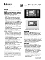
4100ES Remote Annunciator in a Three Bay Cabinet with
Audio Operator Modules; Remote Command Center (left)
and with an InfoAlarm Command Center (right)
Introduction
Remote Annunciator Panels are dedicated purpose
transponders that support fire alarm system status
information. Typical use is when the host fire alarm
control panel is located away from the area where those
responding to a fire situation need status information.
Status and Control. Controls are suitable for
firefighter or other fire brigade responders to access
particular information and for system control. When
equipped with a remote microphone and emergency
voice/alarm communications system control, an
authorized user can take command of the system and
either play selected pre-recorded messages or select
specific tones, or initiate live broadcast information either
globally into the system, or to selected areas.
Remote Master Firefighter Phone. When equipped
with a remote master phone, the authorized user can
connect to remote phone call-in requests and allow callers
to be connected to each other. Although intended for use
in assisting fire responders, these system are also helpful
during system setup and test.
Fire Control Panels
UL, ULC, CSFM Listed; FM Approved; Remote Annunciator Panels
MEA (NYC) Acceptance*
S4100-0038-14 5/2018

Module Bay Description
Remote Annunciators include a bay assembly, a power
distribution interface module (PDI), a Transponder Interface
Module, and an interconnect harness. Communications with
the host fire alarm control panel are via a Remote Unit
Interface (RUI or RUI+) connection that allows for up to
2500 ft (762 m) distance. RUI can communicate with up to a
total of 31 remote devices per master controller (on one or
multiple RUI channels) and can be either Style 4 or Style 7
communications. Wiring can be either shielded or
unshielded, twisted, or untwisted single pair wiring.
4100-9610 Remote Annunciator. This model is for
applications that may require a full complement of the
Remote Annunciator functions (refer to the product
selection lists on pages 3 and 4). Power is from a cabinet
mounted Remote Power Supply (RPS).
4100-9611 Basic Remote Annunciator. For remote
annunciator applications that require less features in the
cabinet, select this model which accepts power from a
separate fire alarm control cabinet. (This model does NOT
accept: a cabinet mounted power supply, expansion phone
cards, Class A phone modules, RS-232 modules, panel
mounted printers, or 24 I/O modules.)
Optional Expansion Bays each include a PDI and
accept a variety of optional modules for specific annunciator
functions.
The Battery Compartment (bottom) accepts two
batteries, up to 50 Ah. Battery mounting does not interfere
with available module space. (Not applicable to the model
4100-9611)
Packaging Availability
Modules are power-limited (except as noted, such as
relay modules)
Enclosure are available for one, two, or three bay sizes
or for cabinet rack mounting
Boxes, doors with tempered glass inserts, and dress
panels are available in beige or red (ordered separately)
Refer to document S4100-0037 for enclosure details
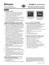
Remote Command Center
The optional Remote Command Center occupies the top
bay of a Remote Annunciator. It provides an LCD status
readout with keyswitch activated control switches and a
local tone-alert sounder. Features are essentially identical
to the Remote LCD Annunciator model 4603-9101
(reference document S4603-0001).
Press ACK located under flashing indicator.
Repeat operation until all events are acknowledged.
Local tone will silence.
Emergency Operating Instructions
Alarm or Warning Condition
How to Acknowledge / View Events
How to Silence Building Signals
System indicator flashing. Tone On. Press Alarm Silence.
How to Reset System
Press System Reset.
Press Ack to silence tone device.
REMOTE COMMAND CENTER
FIRE
ALARM
ALARM
SILENCED
PRIORITY 2
ALARM
SYSTEM
SUPERVISORY
SYSTEM
TROUBLE
POWER
ON
ALARM
ACK
SUPV
ACK
TBL
ACK
ALARM
ACK
ALARM
SILENCE
SYSTEM
RESET
DISPLAY
TIME
4100-1292 Remote Command Center
2 S4100-0038-14 5/2018
Audio
Control
Command
Center
Active
All
Speakers
EVAC
Selective
EVAC
All
Speakers
Talk
Ready
to
Talk
Speaker
Circuits
8th
Floor
7th
Floor
6th
Floor
2nd
Floor
1st
Floor
Phone
Control
Phone
Circuit 1
Phone
Circuit 2
Phone
Circuit 3
Phone
Circuit 4
Phone
Circuit 5
Phone
Circuit 6
Phone
Circuit 7
Phone
Circuit 8
Phone
Control
Phone
Circuit 9
Phone
Circuit 10
Phone
Circuit 11
Phone
Circuit 12
Phone
Circuit 13
Phone
Circuit 14
Phone
Circuit 15
Phone
Circuit 16
4th
Floor
3rd
Floor
5th
Floor
Remote Master
Phone Module
4100-1271
Remote Microphone
Module 4100-1244
8 Switches with 8
Red LEDs,
4100-1280, 2 shown
with typical labels
Single Channel Audio
Control 4100-1252
8 Switches with 8 Red
LEDs, 4100-1280
Push-to-Talk
switch
Remote Annunciator Audio Module Reference

Panel Type
Model
Description
Details and Mounting Reference
4100-9610
Remote Annunciator Panel; requires an internal
power supply
Includes a bay assembly with power distribution board, a Basic
Transponder Interface Module (4100-0620) mounted in Block A, and an
interconnect harness for connecting to 4100ES/4100U Slot modules
Supervisory and Alarm current = 87 mA
4100-9611
Basic Remote Annunciator Panel; requires
power from another cabinet (refer to module
exclusion list on page 2)
Includes a bay assembly with power distribution board, a remotely powered
Transponder Interface Module mounted in Block A, and an interconnect
harness for connecting to 4100ES/4100U Slot modules
Supervisory and Alarm current = 87 mA
Remote Command Center Option (for InfoAlarm Command Center expanded content display products, refer to data sheet
S4100-0045)
Model
Description
Details and Mounting Reference
4100-1292
Panel Mounted LCD Annunciator; 2 line by 40
character LCD with LED illumination; LED
illumination is off during supervisory, turning on
with alarm or when switches are activated
Mounting requires the top bay; 4100ES/4100U flat modules are allowed
behind it; RUI device, RUI/RUI+ connection is required
Supervisory current = 65 mA (w/o backlight)
Alarm current = 140 mA
Emergency Voice/Alarm Communications Operator Interface Options
Model
Description
Details and Mounting Reference
4100-1244
Remote Microphone (mike) Module
Front panel module; requires 2 Slots (4” [51 mm]), space behind accepts
4100ES/4100U flat modules only (requires dedicated wiring to fire alarm
control panel audio control module); Supv. = 2.4 mA, Active = 6 mA
4100-1252
1 Channel (audio or mike)
Operator
Interface
Modules
Single slot modules requiring connection to an LED/switch controller; space
behind accepts 4100ES/4100U flat modules only; adjacent LED/switch
module(s) are required for specific speaker circuit selection (refer to
document S4100-0034 for audio reference and document S4100-0032 for
LED/switch module reference); Supv. = 0, Alarm = 24 mA
4100-1253
1.5 Channel (audio + mike)
4100-1254
2 Channel (full audio)
4100-1255
3-8 Channel
Firefighter Telephone System Products (refer to document S4100-0034 for additional detail)
Model
Description
Details and Mounting Reference
4100-1271
Remote Master Telephone
Mounts in two vertical blocks of bay front, locate as required; space behind
allows 4100ES/4100U flat modules only
4100-1272
Phone Module with 3 Class B phone NACs
Single Block module, mounts to bay mounting plate
Not available
with 4100-9611
4100-1273
Phone Class A Adapter Module
Mounts to 4100-1272, no additional space required
LED and LED/Switch Modules, General Purpose (LED/switch controller and label kit is ordered separately)*
LEDs per Switch
LEDs
Switches
Model
LED Color(s)
Model
LED Color(s)
One
8
8
4100-1280
Red
4100-1281
Yellow
Two
16
8
4100-1282
Red on top, Yellow on bottom
4100-1283
Yellow, top and bottom
Two
16
8
4100-1284
Red on top, Green on bottom
4100-1296
Green on top, Yellow on bottom
One
16
16
4100-1285
Red
4100-1278
8 Red on left, 8 Yellow on right
LEDs per Switch
LEDs
Switches
Model
LED Color(s)
LEDs only
8
LEDs only
4100-1276
Red, pluggable
LEDs only
16
LEDs only
4100-1277
Pluggable LEDs, shipped Red on top, Yellow on bottom
One
16
16
4100-1300
Pluggable LEDs, shipped Red on top, Yellow on bottom;
Note: UL, ULC, and CSFM listed only
One
24
24
4100-1287
Red
LED/Switch Modules, Special Purpose (LED/switch controller, label kit, and separate LEDs are ordered separately)*
Model
Operation
Switch Function (Location)
LED Description
4100-1286
Eight function HOA (On, Off, Auto) Control Module
with labeled switches
On (top)
Green LED
Off (middle)
Red LED
Auto (bottom)
Green LED
4100-1295
Eight function HOA (On, Off, Auto) Control Module, same as 4100-1286 except switches are unlabeled
LED/Switch Controller Modules and Accessories (LED kits for 4100-1276/1277/1300 are on page 4)*
Model
Description
4100-1288
64 LED/64 Switch Controller Module with mounting plate; controls up to 64 LEDs and
interfaces to up to 64 switches; mounts behind the LED/switch modules and has
provisions for one 4100-1289 Controller Module
NOTE: LED/switch controllers and
their connected LED/switch
modules must be in the same bay;
(see data sheet S4100-0032 for
details)
4100-1289
64 LED/64 Switch Controller Module without mounting plate; mounts on extra space of
4100-1288; controls an additional 64 LEDs and 64 switches
4100-1294
LED/Switch Module Slide-in Labels, required when LED/switch modules are present; order one per cabinet
4100-1290
24 Point I/O Module for external connections, select each point as either input or output; 2” (51 mm) wide, 1 Slot; refer to
S4100-0032 for more detail; not available with 4100-9611
* Note: Refer to data sheet S4100-0032 for additional LED/Switch module selections. (continued)
3 S4100-0038-14 5/2018
Product Selection

4 S4100-0038-14 5/2018
Communication Modules (not available with 4100-9611)
Model
Description
Size
Supv.
Alarm
4100-6038
Dual RS-232 Interface, mounts in Slot 3 or Slot 2
1 Slot
132 mA
132 mA
4100-9816
Master Clock Interface Module with one standard RS-232 port (see S4100-0033)
1 Slot
132 mA
132 mA
Panel Mounted Printer (not available with 4100-9611, refer to document S4100-0032 for additional detail)
Model
Description
4100-1293
Panel Mount Thermal Printhead Printer, supplied with one roll of paper; requires 3 expansion slots
4190-9803
Replacement Paper for 4100-1293 Printer, one roll
Power Supplies and Accessories
Model
Voltage/Listing
Description
Size
Supv.
Alarm
4100-5125
120 VAC
UL
Remote Power Supply (RPS); 9 A power supply
with battery charger; Canadian model has low
battery cutout; required for 4100-9610, not
available with 4100-9611
4 Blocks
150 mA
185 mA
4100-5126
120 VAC, Canadian
ULC
4100-5127
220/230/240 VAC
UL
4100-0636
Box Interconnection Harness Kit; order one for each close-nippled cabinet; also used if power is supplied from host
fire alarm control panel
Power Distribution Modules
Model
Voltage
Description
4100-0634
120 VAC
Power Distribution Module (PDM);
select per system voltage
Required for 4100-9610, select one per box or
cabinet rack; not applicable for 4100-9611
4100-0635
220/230/240 VAC
Miscellaneous Accessories
Model
Description
4100-2300
Expansion Bay Hardware, order one for each expansion bay (unless included with selected option)
4100-1279
Single blank 2” display cover, order as required (8 fill a bay front); 2 max. between LED/switch modules
4100-9835
Termination and Address Label Kit (for module marking); provides additional labels for field installed modules
4100-0632
Terminal Block Utility Module; provides 2, 16 position terminal blocks mounted on 4” x 5” single block size, capable of
up to 12 AWG wire (3.31 mm
2
)
4100-0633
Door Tamper Switch (connects to Transponder Interface Module)
4100-9843
Yellow
Kits of 8 LEDs; order as required for 4100-1276/1277/1300 modules
4100-9844
Green
4100-9845
Red
Input Power
Remote Power Supplies (RPS)
120 VAC Models
4 A maximum @ 102 to 132 VAC, 60 Hz
220-240 VAC Models
2 A maximum @ 204 to 264 VAC, 50/60 Hz;
separate taps for 220/230/240 VAC
Power Supply Output Ratings for the Remote Power Supply (RPS)
Total Power Supply Output Rating
9 A total @ nominal 28 VDC, including module currents
and auxiliary power outputs
Output switches to
battery backup
during mains AC
failure or brownout
conditions
Auxiliary Power Tap
2 A maximum
Rated 19.1 to 31.1 VDC
NACs Programmed for Auxiliary Power
2 A maximum per NAC,
5 A maximum total
Battery Charger, Remote Power Supply (RPS) (sealed lead-acid batteries)
Battery capacity range
UL listed for battery charging of 6.2 Ah up to 110 Ah (batteries larger than 50 Ah
require a remote battery cabinet); ULC listed for charging up to 50 Ah batteries
Charger characteristics and performance
Temperature compensated, dual rate, recharges depleted batteries within 48
hours per UL Standard 864, to 70% capacity in 12 hours per ULC Standard S527
Environmental
Operating Temperature Range
32° to 120°F (0° to 49° C)
Operating Humidity Range
Up to 93% RH, non-condensing @ 90° F (32° C) maximum
Product Selection (Continued)
General Specifications

5 S4100-0038-14 5/2018
On
Off
Auto
On
Off
Auto
On
Off
Auto
On
Off
Auto
On
Off
Auto
On
Off
Auto
On
Off
Auto
On
Off
Auto
ON
FEED/
STATUS
OFF
FIRE ALARM FIRST FLOOR ELECTRICAL
CLOSET
LOCATION EL-1-B 12:37:15 20 MAY 13
LOW BATTERY TROUBLE TRANSPONDER 17
12:47:26 20 MAY 13
SYSTEM RESET IN PROGRESS
14:12:23 20 MAY 13
SYSTEM RESET COMPLETE
14:13:02 20 MAY 13
LOGIN
17:23:22 20 MAY 13
PASSWORD ACCEPTED
17:23:25 20 MAY 13
SENSOR 13-9 DISABLED
19:15:09 20 MAY 13
SENSOR 13-9 ENABLED
19:19:03 20 MAY 13
LOGOUT
19:33:02 20 MAY 13
LOGIN
Two bay Remote Annunciator
Panel (non-Audio)
Typical non-audio LED/Switch and
LED modules, with sample
module labeling
Remote Printer option
(can be located where
desired)
On
Off
Aut o
On
Off
Aut o
On
Off
Aut o
On
Off
Aut o
On
Off
Aut o
On
Off
Aut o
On
Off
Aut o
On
Off
Aut o
East
Wing
Fire
Zones
West
Wing
South
Wing
North
Wing
Annex
Garage
Basement
Boiler
Room
Control
East
Wing
West
Wing
South
Wing
North
Wing
Annex
Garage
Basement
Boiler
Room
Fan
On
Fan
Off
East
Wing
West
Wing
South
Wing
North
Wing
Annex
Garage
Basement
Boiler
Room
HVAC
Controls
HVAC
Controls
Door
Release
Manual
Alarms
East
Wing
West
Wing
South
Wing
North
Wing
Annex
Garage
Basement
Boiler
Room
East
Wing
West
Wing
South
Wing
North
Wing
Annex
Garage
Basement
Boiler
Room
East
Wing
Smoke
Alarms
West
Wing
South
Wing
North
Wing
Annex
Garage
Basement
Boiler
Room
A B C D E F G H I
J K L M N O P Q R
'SP' ( ) , # :
S T U V W X Y Z /
ZONE
1
SIG
2
AUX
3
FB
4
IO
5
IDNet
6
P
7
A
8
L
9
NET ADDR
0
C/Exit
Menu Enter
Previous
Next
Page Dn
Page Up
AC
Power
ALARMS
Fire
Alarm
Priority 2
Alarm
WARNINGS
System
Supervisory
System
Trouble
Alarm
Silenced
Fire Alarm
Ack
Priority 2
Ack
Supv
Ack
Trouble
Ack
Alarm
Silence
System
Reset
Ground Fault
Waterflow-West
Waterflow-East
City Disconnect
Manual Evac
Door Holder
Bypass
Drill
Language
Toggle
Smoke Sensor
Almost Dirty Check
Lamp Test
Two Bay Remote Annunciator LED/Switch Module Reference
InfoAlarm Command Center Detail Reference

6 S4100-0038-14 5/2018
On
Off
Auto
On
Off
Auto
On
Off
Auto
On
Off
Auto
On
Off
Auto
On
Off
Auto
On
Off
Auto
On
Off
Auto
HOA Modules, 8 Controls (3 switches each), 24 LEDs:
4100-1286, with labeled switches (shown)
4100-1295, with unlabeled switches (not shown)
4100-1287
24 Switches, 24 LEDs
Visible area
8 1/4" H, 2" W
(210 mm x 51 mm)
Green LED (Auto)
Red LEDs
Custom
label area
Label insert
Primary function labels
One switch
per function
One switch per
control, on/off
Red LED (Off)
Green LED (On)
Fan
On
Fan
Off
16 Switches
with 16 LEDs:
4100-1278, R-Y
4100-1285, R
8 Switches
with 8 LEDs:
4100-1280, R
4100-1281, Y
East
Wing
Control
West
Wing
South
Wing
North
Wing
Annex
Garage
Basement
Boiler
Room
8 Switches
with 16 LEDs:
4100-1282, R/Y
4100-1283, Y/Y
4100-1284, R/G
4100-1296, G/Y
Additional
function labels
Primary
function label
LEDs
Switch
Visible area
8-1/4" H,
2" W
(210 mm
x 51 mm)
Switches
LED/Switch Modules
LED Color Legend:
Red, Yellow, Green;
R/Y = Red on top,
Yellow on bottom;
R-Y = Red on left,
Yellow on right
LED Modules
8 LEDs:
4100-1276, R
(pluggable LEDs)
16 LEDs:
4100-1277, R/Y
(pluggable LEDs)
Designates area
for each column of
switches and LEDs
16 Switches
with 16 LEDs:
4100-1300, R/Y
(pluggable LEDs)
LEDs
Custom
label area
Label insert
Dual Slot LED/Switch Module Detail Reference
Single Slot LED/Switch Module Detail Reference

7 S4100-0038-14 5/2018
Red
LEDs
Blank switches can be
programmed as required
4100-1252,
Single Channel
Audio
Control
Command
Center
Active
All
Speakers
EVAC
Selective
EVAC
Local
Speaker
All
Speakers
Talk
Ready
to
Talk
4100-1254,
Dual Channel
Audio
Control
Command
Center
Active
All
Speakers
EVAC
Selective
EVAC
Selective
Alert
Local
Speaker
EVAC
Local
Speaker
Alert
All
Speakers
Talk
Ready
to
Talk
4100-1253,
1.5 Channel
Audio
Control
Command
Center
Active
All
Speakers
EVAC
Selective
EVAC
Selective
Alert
Local
Speaker
EVAC
All
Speakers
Talk
Ready
to
Talk
4100-1255,
3-8 Channel
Visible area
8-1/4" H, 2" W
(210 mm x 51 mm)
Green
LEDs
Green
LED
Audio
Control
Command
Center
Active
All
Speakers
EVAC
Start
All
Selected
All
Speakers
Talk
Ready
to
Talk
Green
LEDs
Green
LEDs
Green
LEDs
Green
LED
Green
LED
Green
LED
Red
LEDs
Red
LEDs
Red
LEDs
Subject
Data Sheet
Subject
Data Sheet
Battery and Battery Cabinet Reference for
4100ES
S2081-0006
4100ES Enclosures
S4100-0037
110 Ah Batteries and Cabinets for 4100ES
S2081-0012
InfoAlarm Command Center with SPS Power
Supplies
S4100-0045
Seismic Battery Brackets Reference
S2081-0019
NDU with SPS Power Supplies for ES Net
S4100-0077
Graphic I/O Modules for 4100ES, 4010ES,
4007ES
S4100-0005
4100ES Basic Panels with EPS Power
Supplies
S4100-0100
4100ES Basic Panels with SPS Power
Supplies
S4100-0031
InfoAlarm Command Center with EPS Power
Supplies
S4100-0101
4100ES LED/Switch Modules & Printer
S4100-0032
NDU with EPS Power Supplies for 4120
Network
S4100-0102
NDU with SPS Power Supplies for 4120
Network
S4100-0036
NDU with EPS Power Supplies for ES Net
S4100-0104
Slot 1 Slot 8Slot 7Slot 6Slot 5Slot 4Slot 3Slot 2
Expansion Bay Chassis
Block A
Block B
Block C
Block D
Block E
Block F
Block G
Block H
Size Definitions:
Block = 4” W x 5” H card area
Slot = 2” W x 8” H motherboard with
daughter card
Audio Control Module Detail
Additional 4100ES Data Sheet Reference
Expansion Bay Module Loading Reference

TYCO, SIMPLEX, and the product names listed in this material are marks and/or registered marks. Unauthorized use is strictly prohibited.
Door thickness
4-3/4"(121 mm)
Exposed cabinet for
semi-flush mounting
1-3/8" (35 mm)
minimum
Exposed door and cabinet
for semi-flush mounting
6-1/8" (156 mm) minimum
24" (610 mm)
11-11/16"
(296 mm)
6-29/32"
(175 mm)
4" stud
6" stud
Knockout screw/nail holes
(for semi-flush mounting)
Stud alignment
markers, each side
Wall board reference
for semi-flush
mounting, 6" stud
Optional semi-flush
trim kit reference
Front view, box outline without door Side view with door attached
2 Bay height =
40" (1016 mm)
3 Bay height =
56" (1422 mm)
1 Bay height =
22" (559 mm)
Doors can be hinged left or right
Tyco Fire Protection Products • Westminster, MA • 01441-0001 • USA S4100-0038-14 5/2018
www.simplexgrinnell.com
© 2018 Tyco Fire Protection Products. All rights reserved. All specifications and other information shown were current as of document revision date and are subject to change without notice.
Wall Mounted Enclosure Installation Reference
NOTE: A system ground must be provided for Earth Detection and transient protection devices. This connection
shall be made to an approved, dedicated Earth connection per NFPA 70, Article 250, and NFPA 780.
/