Page is loading ...


KLIC-DD v3
http://www.zennio.com Technical Support: http://support.zennio.com
2
CONTENTS
Contents ........................................................................................................................................ 2
Document Updates ....................................................................................................................... 3
1 Introduction .......................................................................................................................... 4
1.1 KLIC-DD v3 ........................................................................................................................ 4
1.2 Installation ........................................................................................................................ 5
1.3 Start-Up and Power Loss .................................................................................................. 6
2 Configuration......................................................................................................................... 7
2.1 General ............................................................................................................................. 7
2.2 AC Gateway ...................................................................................................................... 9
2.2.1 Configuration ........................................................................................................... 9
2.2.2 Initial Configuration ............................................................................................... 22
2.2.3 Scenes .................................................................................................................... 24
2.2.4 Error Handling ........................................................................................................ 26
2.3 Inputs ............................................................................................................................. 27
2.3.1 Binary Input ............................................................................................................ 27
2.3.2 Temperature Probe ................................................................................................ 27
2.3.3 Motion Detector .................................................................................................... 27
2.4 Logic Functions ............................................................................................................... 29
ANNEX I. Communication Objects............................................................................................... 30

KLIC-DD v3
http://www.zennio.com Technical Support: http://support.zennio.com
3
DOCUMENT UPDATES
Version
Changes
Page(s)
[1.1]_a
Changes in the application program:
- AC unit operation time counter.
- Temperature measured by the A/C Unit.
- Advanced climate control through external reference
temperature.
- LED notification of internal errors.
- Optimisation of the Heartbeat, binary inputs,
temperature probe and motion detector module.
-
AC unit operation time counter.
10, 21-22
Temperature measured by the A/C Unit.
9, 14
Advanced climate control through external reference
temperature.
9, 16-17
LED notification of internal errors.
26

KLIC-DD v3
http://www.zennio.com Technical Support: http://support.zennio.com
4
1 INTRODUCTION
1.1 KLIC-DD V3
KLIC-DD v3 from Zennio is a gateway that provides full-duplex communication between
the KNX home automation system and domestic range Daikin air-conditioning
systems through the S21 port of interior units. KLIC-DD v3 adds component
improvements and electrical safety over the previous KLIC-DD3.
Because of this bidirectional communication, the air conditioning system can be
controlled from the home automation system in the same manner as it is through its own
controls. Moreover, the actual status of the unit can be monitored and periodically sent
to the KNX bus to inform other devices.
The most outstanding features of KLIC-DD v3 are:
Bidirectional control of domestic range Daikin A/C units through the S21 port
of interior units.
Control of the main functions of the domestic range Daikin A/C unit: On/Off,
temperature, mode of operation, fan speed, swing of the flaps, etc.
Error management to handle specific error codes from the A/C unit itself as
well as any communication issues that may arise.
Up to five scenes.
Two analogue-digital inputs, for the connection of temperature probes,
motion detectors or binary pushbuttons or switches.
10 customisable, multi-operation logic functions.
Heartbeat or periodic “still-alive” notification.

KLIC-DD v3
http://www.zennio.com Technical Support: http://support.zennio.com
5
1.2 INSTALLATION
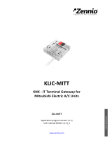
Figure 1. Element scheme.
KLIC-DD v3 connects to the KNX bus via the corresponding built-in terminal (5). Once
the device is provided with power from the KNX bus, both the physical address and the
KLIC-DD v3 application program can be downloaded.
This device does not need any external power as it is entirely powered through the KNX
bus.
The remaining elements are described next.
Prog./Test button (2): a short press on this button will set the device into the
programming mode, making the associated LED (1) light in red.
Note: if this button is held while plugging the device into the KNX bus, the
device will enter into safe mode. The LED will blink in red every 0.5 seconds
Analogue-Digital Inputs (3): input ports for the stripped cables of external
elements such as switches, motion detectors, temperature probes, etc.
Communication cable (4): 5-wire cable with S21 connector that will connect
KLIC-DD v3 and the A/C unit. The other end of the cable, therefore, is intended
to be connected to the S21 connector in the PCB board of the internal unit.
1. Prog./Test LED indicator.
2. Prog./Test button.
3. Analogue/digital inputs.
4. S21 communication cable.
5. KNX connector.

KLIC-DD v3
http://www.zennio.com Technical Support: http://support.zennio.com
6
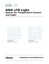
Figure 2. Connecting KLIC-DD v3 to the A/C unit.
Important: Control the A/C unit both through its incorporated wired remote control and
through KLIC-DD v3 is not possible, due to both of them use the S21 port. By the other
hand, if the wireless control is employed, it must be considered that orders sent from the
wireless control will have a higher priority than those sent through KLIC-DD v3. In
addition, certain parameterisations made in the device can be ignored.
For detailed information about the technical features of KLIC-DD v3, as well as on
security and installation procedures, please refer to the device Datasheet, bundled in
the device packaging and also available at http://www.zennio.com.
1.3 START-UP AND POWER LOSS
Depending on the configuration, some specific actions will be performed during the
device start-up. The integrator may set up an initial status to be sent to the A/C unit after
the bus power recovery, and whether certain objects should be sent to the bus after the
power recovery, as described in later sections.
On the other hand, when a bus power failure takes place, the device will interrupt any
pending actions, and will save its state so it can be recovered once the power supply is
restored.

KLIC-DD v3
http://www.zennio.com Technical Support: http://support.zennio.com
7
2 CONFIGURATION
2.1 GENERAL
After importing the corresponding database in ETS and adding the device into the
topology of the desired project, the configuration process begins by entering the
Parameters tab of the device.
ETS PARAMETERISATION
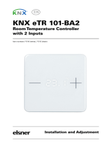
The “General” screen is shown in the first place, containing the following parameters:
Figure 3. General.
AC Gateway [enabled]
1
: entails all functions specific to KLIC-DD v3, relating
to communication with the A/C unit and management of the climate control
system. For more information, see section 2.2.
Inputs [disabled/enabled]: enables or disables the “Inputs” tab in the tree on
the left. For more information, see section 2.3.
Logic Functions [disabled/enabled]: enables or disables the “Logic Function”
tab in the tree on the left. For more information, see section 2.4.
Heartbeat (Periodic Alive Notification) [disabled/enabled]: this parameter
lets the integrator incorporate a one-bit object to the project (“[Heartbeat]
Object to Send ‘1’”) that will be sent periodically with value “1” to notify that
the device is still working (still alive).
1
The default values of each parameter will be highlighted in blue in this document, as follows: [default/rest
of options].

KLIC-DD v3
http://www.zennio.com Technical Support: http://support.zennio.com
8
Figure 4. Heartbeat.
Note: the first sending after download or bus failure takes place with a delay of
up to 255 seconds, to prevent bus overload. The following sendings match the
period set.
Regardless of the above parameters, the following objects are available by default:
“[AC] On/Off” and “[AC] On/Off (Status)”: allow switching on (value “1”) and
off (value “0”) the A/C unit or reading the current status, respectively.
“[AC] Temperature Setpoint” and “[AC] Temperature Setpoint (Status)”:
allow setting the desired temperature setpoint or reading the current value,
respectively. See section 2.2.1 for further information.
“[AC] Mode” and “[AC] Mode (Status)”: allow setting the desired operation
mode (either Automatic, Heating, Cooling, Fan or Dry) or reading the current
mode, respectively. See section 2.2.1 for further information.
“[AC] Fan: Percentage Control” and “[AC] Fan: Percentage Control
(Status)”: allow setting one of the 5 fan levels or auto mode (automatic, fan 1,
fan 2, fan3, fan 4 or fan 5) or reading the current fan level, respectively. See
section 2.2.1.
Several error objects. See section 2.2.4.

KLIC-DD v3
http://www.zennio.com Technical Support: http://support.zennio.com
9
2.2 AC GATEWAY
2.2.1 CONFIGURATION
KLIC-DD v3 allows controlling and monitoring an air-conditioning unit in the same way it
would be through the wired remote control it is provided with.
Through the KNX bus, KLIC-DD v3 can be sent orders to control the following basic
functions of the air conditioning unit:
On/Off switch of the air-conditioning unit.
Operation mode: automatic, heating, cooling, fan and dry.
Temperature setpoint, which can be modified within a specific range of
values, depending on the capabilities of the specific A/C unit being controlled.
Fan speed: 5 levels and automatic mode.
Flaps swing: vertical flaps, horizontal flaps or both types depending on A/C
unit.
Moreover, KLIC-DD v3 allows configuring several advanced functions:
Temperature measured by the AC unit: allows enabling an object which
provides the value of the internal temperature probe. The automatic sending
can be configured based on: a period of time, a change in value or a
combination of both.
Setpoint limits, to restrict the range for the temperature setpoint.
External reference temperature: which allows enabling an object to use an
external reference temperature, provided by a temperature probe.
Humidity: allows enabling six objects for the humidity control function. The
availability of humidity control depends on A/C unit model.
Automatic off, which allows an automatic and temporary switch-off of the unit
(after a pre-established delay, if desired) when the communication object
associated to this function is triggered due to a certain event.

KLIC-DD v3
http://www.zennio.com Technical Support: http://support.zennio.com
10
Initial configuration, which allows establishing the desired initial parameters
for the state of the A/C unit after programming or restarting the device.
Scenes, which allows defining specific climate control presets, to be sent to
the machine on the reception of scene orders from the KNX bus.
Operating time: provides the A/C unit operating time in hours and/or seconds.
These functionalities imply changes in the state of the A/C unit, which therefore notifies
KLIC-DD v3 periodically about the current state. When KLIC-DD v3 is notified about a
change, it updates the status objects and sends them to the KNX bus. In addition, KLIC-
DD v3 provides an error management function (see section 2.2.4), which allows
sending messages to the KNX bus in case the A/Cunit reports any errors.
ETS PARAMETRIZATION
The “Configuration” tab under AC Gateway provides the following parameters:
Figure 5. AC Gateway. Configuration.

KLIC-DD v3
http://www.zennio.com Technical Support: http://support.zennio.com
11
OPERATION MODES
KLIC-DD v3 allows controlling the A/C unit operating mode through the following objects,
available by default:
“[AC] Mode”: 1-Byte object which allows selecting the A/C unit operation
mode. There will be only taken in account values that are appropriated with
some of available modes in Daikin units, which are represented in Table 1.
“[AC] Mode (Status)”: 1-Byte object which allows knowing the A/C unit
operating mode status.
Object Value
A/C unit mode
0
Auto
1
Heating
3
Cooling
9
Fan only
14
Dry
Table 1. A/C unit operating modes.
Note: In case of having selected humidifying unit, other additional modes will be
available. See paragraph Humidity in this section.
Additionally, a simplified mode can be configured to select Cooling and Heating mode.
Simplified Mode [disabled/enabled]: in addition to the “[AC] Mode” and “[AC]
Mode (Status)” one-byte objects, available by default, it is possible to
commute and to verify the current operation mode through the following one-
bit objects, which get enabled after activating this parameter:
“[AC] Simplified Mode”, which allows switching to the Cooling mode by
sending it a “0” and to the Heating mode by sending it a “1”.
“[AC] Simplified Mode (Status)”, which will send a value of “0” when the
mode switches to Cooling or to Dry, or a value of “1” when it switches to
Heating. The Fan mode is not reflected in the value of this object. In Auto
mode the value will be actualized depending of the current mode operating:
Auto-Cooling (“0”) or Auto-Heating (“1”).

KLIC-DD v3
http://www.zennio.com Technical Support: http://support.zennio.com
12
FLAPS
Horizontal Flaps [disabled/enabled]: when enabled, “[AC] Horizontal Flaps:
Swing” and “[AC] Horizontal Flaps: Swing (Status)” 1-bit objects will be
available in order to commute or consult the operating state.
Vertical Flaps [disabled/enabled]: when enabled, “[AC] Vertical Flaps:
Swing” and “[AC] Vertical Flaps: Swing (Status)” 1-bit objects will be
available for commuting or consulting the operating state.
In both cases the following parameter:
Swing Object Polarity [0 = Swing On; 1 = Swing Off / 0 = Swing Off; 1 =
Swing On]: defines which value activates each swing.
Figure 6. AC Gateway. Configuration. Flaps.
FAN
The Fan function allows sending the A/C unit orders to switch the ventilation speed along
the available levels (5 levels and automatic mode). To that end, KLIC-DD v3 provides a
percentage control through the objects “[AC] Fan: percentage control” y “[AC] Fan:
percentage control (Status)”, available by default.
Table 2 reflects the percentage values that refer to several ventilation levels:

KLIC-DD v3
http://www.zennio.com Technical Support: http://support.zennio.com
13
Control Value
Status Value
Sent level to the A/C unit
0%
0%
Automatic mode
1-20%
20%
1 (minimum)
21-40%
40%
2
41-60%
60%
3
61-80%
80%
4
81-100%
100%
5 (maximum)
Table 2: Fan Speed.
In addition, automatic fan speed mode can be activated through the following
parameter:
Individual Object for Automatic Mode [disabled/enabled]: enables the “[AC]
Fan: Automatic” and “[AC] Fan: Automatic (Status)” one-bit objects, which
will let activating/deactivating the automatic mode or reading the current status,
respectively. Moreover, the polarity can be configured by parameter:
Automatic Mode Object Polarity [0 = Automatic On; 1 = Automatic Off / 0
= Automatic Off; 1 = Automatic On]: sets the polarity of the above objects.
Figure 7. AC Gateway. Configuration. Fan.
If individual object for automatic mode is enabled, the behaviour is as follows:
When activating automatic mode, fan percentage status will be 0%.
When deactivating automatic mode, fan level 1 is set.
Notes:
In automatic mode, effective fan speed it is not possible to know the effective
fan speed, so, when activated, fan speed status will stay with 0% value.
In dry mode, A/C unit sets fan speed in automatic mode. Due to this fact the
fan speed control orders will be ignored during this mode.

KLIC-DD v3
http://www.zennio.com Technical Support: http://support.zennio.com
14
TEMPERATURE MEASURED BY THE A/C UNIT
Monitoring [disabled/enabled]: enables the “[AC] AC Unit Measured
Temperature” two-byte object, which provides the value of its internal
temperature sensor, which is used by the AC machine to execute the control
loop. Once enabled, a secondary parameter will show:
Sending Type [Variation / Periodic / Periodic + Variation]: sets whether the
above object should be sent only in case of a change in the value,
periodically or both, respectively. The latter two options bring entail one
more parameter:
Period [1…3600][s] [1…15…1440][min] [1…24][h]: sets the cycle time
for the periodic sending.
Figure 8. AC Gateway. Configuration. Temperature measured by the AC unit.
TEMPERATURE SETPOINT
The following objects to control and supervise setpoint temperature will be available by
default:
“[AC] Temperature Setpoint”: 2-Byte object that allow selecting decimal
temperature values that belong to the range [10º-32º].
“[AC] Temperature Setpoint (Status)”: 2-Byte object that provides the
Temperature setpoint status.
Note: A X.Y value will be rounded to X.0 if [Y < 5] or to X.5 if [Y ≥ 5].
Status object will be updated to the last setpoint temperature value received by the A/C
unit after a complete communication cycle and will be sent to KNX bus every time that
its value changes.

KLIC-DD v3
http://www.zennio.com Technical Support: http://support.zennio.com
15
Setpoint limits can be configured by parameter:
Setpoint Limits [disabled/enabled]: allows restricting the range of the
temperature setpoint (from below in the Cooling, Dry and Auto modes and from
above in the Heating and Auto modes), provided that the limits are still within
the predefined limits of the A/C unit. When KLIC-DD v3 receives an order to
send the A/C unit a setpoint which is greater (or lower) than the configured
limits, it will actually send the limit value.
Minimum (Cooling / Auto / Dry Mode) [10…32][ºC]: sets the upper
limit.
Maximum (Heating / Auto Mode) [10…32][ºC]: sets the lower limit.
Figure 9. AC Gateway. Configuration. Temperature setpoint.
Once these limits are enabled, several objects to modify them at run time will be
available. The values of this objects will be restricted to an interval which is defined by
the absolute limits established by the A/C unit (10ºC to 32ºC).
“[AC] Temperature Setpoint: Lower Limit”: 2-Byte object that allows
changing the lower limit at run time.
“[AC] Temperature Setpoint: Lower Limit (Status)”: 2-Byte object with the
lower limit current value.
“[AC] Temperature Setpoint: Upper Limit”: 2-Byte object that allows
changing the upper limit at run time.
“[AC] Temperature Setpoint: Upper Limit (Status)”: 2-Byte object with the
upper limit current value.

KLIC-DD v3
http://www.zennio.com Technical Support: http://support.zennio.com
16
Notes:
If [Minimum] ≥ [Maximum], limits will not be taken in account in Auto mode due
to the incongruity. In this case, default values will be used.
These parameters only can be set as integer values in ETS. However, at run
time the associated objects allow decimal values.
The A/C unit set a fixed temperature setpoint in Fan and Dry mode, this is the
reason why KLIC-DD v3 will not send the setpoint value to A/C unit, however
the value will be saved to send when leaving these modes.
The setpoint limits set by the A/C unit on each operating mode are indicated in
Table 3:
Mode
Temperature Setpoint
Auto
[18º-30º]
Cooling
[18º-32º]
Heating
[10º-30º]
Fan
Not available
Dry
Not available
Table 3: Interior setpoint limits of A/C unit
REFERENCE TEMPERATURE
To control the temperature setpoint, the following objects are enabled by default:
Figure 10. AC Gateway. Configuration. Reference temperature.
External Reference Temperature Object [disabled/enabled]: enables the 2-
byte object “[AC] External Reference Temperature”, which provides the value
of an external temperature sensor, which is used by the AC machine as the
reference to execute the control loop.
If no temperature values are received after 3 minutes, values of the internal
probe will be recuperated again to execute temperature control, in the same
way as it will be controlled if KLIC-DD v3 was configured disabling this option.

KLIC-DD v3
http://www.zennio.com Technical Support: http://support.zennio.com
17
If a new external temperature value is received, the control will be again
executed by using this external value. The allowed value range is [0-70] ºC (if
different values are received, they will be ignored).
Actually, the machine will continue to executing its control loop with the same reference
temperature, but the KLIC will send an adjusted temperature setpoint following the
formula:
Adjusted setpoint temperature = Setpoint temp. + [AC measured temp. – External
reference temp.]
Important: If the external reference temperature is enabled, it is recommended not to
use the wired remote control or, failing that, not to change the setpoint from it.
HUMIDITY
The availability of humidity control depends on A/C unit model and can be activated by
the parameter:
Humidifying Unit [disabled/enabled]: enables humidity control function.
Once the humidifying unit is enabled in AC Gateway Configuration section, the following
objects are available:
“[AC] Humidity Adjust: Operation Point (%)”: 1-Byte object to select the
desired humidity operation point. Table 4 represents the percentage values
that refer to each of the 5 humidity operation points.
“[AC] Humidity Adjust: Operation Point (%) (Status)”: 1-Byte object that
provides the humidity operation point.
Note: A humidity operation point can only be established when the current operating
mode allows humidity control (Cooling, Heating and Dry mode). In Automatic or Fan
mode the humidity cannot be controlled. So, if a humidity operation point is sent during
these modes, it will be ignored.

KLIC-DD v3
http://www.zennio.com Technical Support: http://support.zennio.com
18
Control
Value
Status
Value
Level Sent
to A/C unit
Level Description
0%
0%
Off
Control Humidity Off
1-25%
25%
Low
Humidification/dehumidification with low energy
26-50%
50%
Standard
Humidification/dehumidification with moderate
energy
51-75%
75%
High
Humidification/dehumidification with high energy
76-100%
100%
Continuous
Continuous humidification/dehumidification
Table 4. Humidity operation levels.
Domestic range Daikin A/C units with humidity control, allow other operation modes apart
from traditional modes (Auto, Fan, Cooling, Heating and Dry):
Ururu humidification operation: this operation permits to raise the humidity.
This mode can only be activated while A/C unit is off (if an order of Ururu
activation is received while the unit is on, it will be ignored). To activate the
Ururu humidification operation or to supervise its status, the following objects
are available:
“[AC] Ururu”: 1-bit object to activate or deactivate Ururu humidification.
“[AC] Ururu (Status)”: 1-bit object that provides Ururu humidification
status.
Once Ururu humidification is activated, A/C unit turns on, activates Heating
mode and the humidify process starts. Fan speed level will remain and
temperature setpoint will not be accessible (in case of modifying temperature
setpoint while this mode is running, Ururu humidification mode will be
deactivated, and Humid heating operation, that will be explain later, will be
activated).
When deactivating Ururu humidification mode (by sending “0” through its
object) or when sending “0%” humidity adjust, the A/C unit will operate in
Heating mode.
Note: After bus failure and/or after a programming, Ururu humidification mode,
in case of being configured, will be deactivated.

KLIC-DD v3
http://www.zennio.com Technical Support: http://support.zennio.com
19
Humid heating operation: this operation permits to raise the temperature and
humidity. The ways to active this operation are:
While in Heating mode, modifying the humidity adjust.
While in Ururu humidification mode, modifying the temperature setpoint.
Once Humid heating is operating, heating mode and a low humidity operation
point will be activated. Fan speed level is not modified, keeping its previous
value.
Sarara Drying Operation: this operation permits to lower humidity (actually,
is the same functionality than Dry mode).
To activate Sarara Drying operation, there are available the next objects:
“[AC] Sarara: 1-Bit object to activate or deactivate Sarara Drying
operation.
“[AC] Sarara (Status)”: 1-Bit object that provides Sarara Drying operation
status.
Once Sarara drying operation is activated, Dry mode and a low humidity
operation point will be established. Fan speed level will be set to Automatic and
temperature setpoint will not be accessible (in case of modifying temperature
setpoint while this mode is running, Sarara drying mode will be deactivated,
and Dry cooling mode, that will be explain after, will be activated).
Note: Activating Sarara drying operation involves activating Dry mode and vice
versa.
When deactivating Sarara drying operation (by sending “0” through its object)
or when sending “0%” humidity adjustment, the A/C unit will operate in Cooling
mode.
Dry cooling operation: this operation permits to lower temperature and
humidity. The ways to active this operation are:
While in Cooling mode, modifying humidity adjust.

KLIC-DD v3
http://www.zennio.com Technical Support: http://support.zennio.com
20
While in Sarara Drying operation, modifying temperature setpoint.
Once Dry cooling operation is activated, Cooling mode and a low humidity
operation point will be established. Fan speed level will be set to Automatic.
AUTOMATIC OFF
Automatic Off [disabled/enabled]: enables the “[AC] Automatic Off” binary
object, which lets performing a temporary switch-off of the A/C unit by sending
it a value of “1” and a later switch-on by sending it a value of “0”. This object
will be typically linked to a window sensor or a similar event trigger. Automatic
off will be also active if the unit is previously in off state, so, the unit will not be
able of being on until this situation finishes.
During the temporary switch-off state, KLIC-DD v3 will still monitor any control
orders being received (setpoint, fan speed, etc.), so they can be applied once
it leaves such state.
Automatic Off Object Polarity [0 = Activate; 1 = Deactivate / 0 =
Deactivate; 1 = Activate]: sets the polarity of the above object.
Automatic Off Delay [1…60…3600][s]: sets the time, in seconds, KLIC-DD
v3 waits before switching the A/C machine off. Any switch-off order received
during the delay will abort the time count.
Figure 11. AC Gateway. Configuration. Automatic Off.
Note: switch-on orders sent to the A/C unit from a wireless control have a higher
priority than the Auto Off mode.
/