
fåëí~ää~íáçå=oÉèìáêÉãÉåíë
NOKOMNQ
pfkfrp=L=pfkfrp=`p=L=pfkfrp=qp
kÉï=~ë=çÑW==
båÖäáëÜ
=
Installation requirements


63 22 668 D3561
D3561.021.01.06.02 12.2014 3
Sirona Dental Systems GmbH Table of contents
Installation Requirements SINIUS / SINIUS CS / SINIUS TS
båÖäáëÜ
Table of contents
1General information.................................................................................................. 5
1.1 Notes on the installation prerequisites .......................................................... 5
1.2 Structure of the document............................................................................. 6
1.2.1 Identification of danger levels........................................................... 6
1.2.2 Formats and symbols used .............................................................. 6
2Safety information .................................................................................................... 7
2.1 Installation by qualified personnel ................................................................. 7
2.2 Radiotelephones ........................................................................................... 7
2.3 Modifications and extensions of the system.................................................. 7
2.4 Power connection.......................................................................................... 8
3On-site installation.................................................................................................... 9
3.1 Substrate, floor.............................................................................................. 9
3.1.1 Load-bearing capacity of the floor.................................................... 9
3.1.2 Tensile forces................................................................................... 9
3.1.3 Stability............................................................................................. 10
3.2 Connection to the public drinking water system............................................ 11
3.3 Media quality ................................................................................................. 12
3.4 Underfloor installation of supply lines............................................................ 15
3.4.1 Installation template ......................................................................... 15
3.4.2 Installation of the supply line in the termination panel...................... 17
3.5 Cleaning the air and water pipes................................................................... 18
3.6 Underfloor installation of the PC connections ............................................... 19
4Dimensions, technical data ...................................................................................... 20
4.1 SINIUS dimensions, scale bar 1:20 .............................................................. 20
4.1.1 Dimensions of the treatment room ................................................... 20
4.1.2 Side view.......................................................................................... 21
4.1.3 Top view........................................................................................... 22
4.1.4 Top view with options....................................................................... 23
4.1.5 Size of the treatment room with HELIODENT Plus.......................... 24
4.1.6 Side view with HELIODENT Plus..................................................... 25

63 22 668 D3561
4D3561.021.01.06.02 12.2014
Table of contents Sirona Dental Systems GmbH
Installation Requirements SINIUS / SINIUS CS / SINIUS TS
4.2 SINIUS CS dimensions, scale bar 1:20 ........................................................ 26
4.2.1 Dimensions of the treatment room ................................................... 26
4.2.2 Side view.......................................................................................... 27
4.2.3 Top view........................................................................................... 28
4.2.4 Top view with options....................................................................... 29
4.2.5 Size of the treatment room with HELIODENT Plus.......................... 30
4.2.6 Side view with HELIODENT Plus..................................................... 31
4.3 SINIUS TS dimensions, scale bar 1:20......................................................... 32
4.3.1 Dimensions of the treatment room ................................................... 32
4.3.2 Side view.......................................................................................... 33
4.3.3 Top view........................................................................................... 34
4.3.4 Top view with options....................................................................... 35
4.3.5 Size of the treatment room with HELIODENT Plus.......................... 36
4.3.6 Side view with HELIODENT Plus..................................................... 37
4.4 Mounting plates............................................................................................. 38
4.5 Information on planning for the practice........................................................ 40
4.6 Technical data............................................................................................... 41
4.7 Standards/Approvals..................................................................................... 44
5Electromagnetic compatibility................................................................................... 46
5.1 Accessories................................................................................................... 46
5.2 Electromagnetic emission ............................................................................. 47
5.3 Interference immunity.................................................................................... 48
5.4 Working clearances....................................................................................... 50
5.5 Foot control wireless interface ...................................................................... 51
6Checklist................................................................................................................... 52
6.1 Installation site .............................................................................................. 52
6.2 Construction requirements ............................................................................ 53
6.3 IT hardware ................................................................................................... 54
6.4 Network ......................................................................................................... 55
6.5 Data processing ............................................................................................ 56

63 22 668 D3561
D3561.021.01.06.02 12.2014 5
Sirona Dental Systems GmbH 1General information
Installation Requirements SINIUS / SINIUS CS / SINIUS TS 1.1Notes on the installation prerequisites
båÖäáëÜ
1General information
1.1 Notes on the installation prerequisites
HYBRID product
This document describes the installation prerequisites for all versions of
the SINIUS / SINIUS CS / SINIUS TS treatment center.
It contains the following information:
● Required information for practice planning.
● Information for the installer and operator regarding the necessary
quality of the air and water supply media.
● Information for the installer, such as how to implement the
connections for air, water, waste water, suction air and the power
supply.
● Information on the cabling of the PCs to be connected.
● Information about electromagnetic compatibility and the prerequisites
for setting up the treatment center.
● A checklist to ensure that all installation requirements have been
fulfilled.
Reference to HYBRID installation instructions
The subsequent installation of the treatment center is described in the
installation instructions (REF 63 22 627).
You will also need the drilling template (REF 63 34 291) for the safe and
secure attachment of the treatment center to the floor.

63 22 668 D3561
6D3561.021.01.06.02 12.2014
1General information Sirona Dental Systems GmbH
1.2Structure of the document Installation Requirements SINIUS / SINIUS CS / SINIUS TS
1.2 Structure of the document
1.2.1 Identification of danger levels
To prevent personal injury and material damage, please observe the
warning and safety information provided in this document. Such
information is highlighted as follows:
Tip: Information on making work easier.
1.2.2 Formats and symbols used
The formats and symbols used in this document have the following
meaning:
DANGER
An imminent danger that could result in serious bodily injury or death.
WARNING
A possibly dangerous situation that could result in serious bodily injury
or death.
CAUTION
A possibly dangerous situation that could result in slight bodily injury.
NOTICE
A possibly harmful situation which could lead to damage of the product
or an object in its environment.
IMPORTANT
Application instructions and other important information.
Prerequisite
1. First action step
2. Second action step
or
➢ Alternative action
Result
➢Individual action step
Prompts you to do something.
see "Formats and symbols
used [ → 6]"
Identifies a reference to another text
passage and specifies its page
number.
● List Designates a list.
"Command/menu item" Indicates commands, menu items or
quotations.

63 22 668 D3561
D3561.021.01.06.02 12.2014 7
Sirona Dental Systems GmbH 2Safety information
Installation Requirements SINIUS / SINIUS CS / SINIUS TS 2.1Installation by qualified personnel
båÖäáëÜ
2Safety information
2.1 Installation by qualified personnel
Installation by qualified personnel
The installation of the supply connections must be carried out by qualified
technicians only.
Electrical and water supply installations; reference for INST suction machines
2.2 Radiotelephones
Mobile RF communications equipment can affect electro-medical
equipment. Therefore, the use of mobile wireless phones in medical office
or hospital environments must be prohibited.
2.3 Modifications and extensions of the system
Modifications to this system which might affect the safety of the system
owner, patients, or other persons are prohibited by law.
For reasons of product safety, this product may be operated only with
original Sirona accessories or third-party accessories expressly approved
by Sirona. The user assumes the risk of using non-approved accessories.
If any devices not approved by Sirona are connected, they must comply
with the applicable standards, e.g.:
● IEC 60950-1 for information technology equipment (e.g. PC) and
● IEC 60601-1 for medical electrical equipment.
The treatment center monitor must fulfill the requirements of the
IEC 60950-1 standard.
The loudspeaker port of the monitor may be connected only to a device
that complies with IEC 60950-1 (e.g. a PC) or
IEC 60601-1. Under no circumstances may it be connected to a stereo
system or the like.
If a system is created during the installation process, the requirements of
IEC 60601-1, 3rd edition, must be fulfilled. The person assembling the
system assumes responsibility for ensuring conformity, e.g. acc. to
Directive 93/42/EEC.
WARNING
Professional installation
Comply with the national regulations for electrical installation
(e.g. IEC 60364-1, VDE 0100-100, IEC 60364-7-710, VDE 0100-710,
National Electrical Code).
Comply with the national regulations for water supply installations
(e.g. EN 1717) and sewage installations (e.g. EN 12056-1).
For suction lines: adhere to the specifications in the installation
instructions for "Suction machines".

63 22 668 D3561
8D3561.021.01.06.02 12.2014
2Safety information Sirona Dental Systems GmbH
2.4Power connection Installation Requirements SINIUS / SINIUS CS / SINIUS TS
2.4 Power connection
WARNING
Shock hazard
It is essential that you switch off the power supply PRIOR to beginning
the installation. There is a risk of electric shock. People can be injured
or electrical components of the unit destroyed.

63 22 668 D3561
D3561.021.01.06.02 12.2014 9
Sirona Dental Systems GmbH 3On-site installation
Installation Requirements SINIUS / SINIUS CS / SINIUS TS 3.1Substrate, floor
båÖäáëÜ
3On-site installation
3.1 Substrate, floor
Level floor, steel adapter plate
Unevenness The floor must be level and horizontal in accordance with DIN 18 202.
In the case of an uneven floor, the steel adapter plate must be used; see
Mounting plates [ → 38].
3.1.1 Load-bearing capacity of the floor
Load capacity:
The minimum load-bearing capacity of the floor must be 0.5 N/cm2
(corresponds to around 500 kg/m2).
3.1.2 Tensile forces
The floor must be able to accommodate tensile forces of > 1 kN at each
of the marked screw fastening points (A).
It may be necessary to reinforce the surface beneath the floor.
When using a mounting plate (see Mounting plates [ → 38]) this
requirement is mandatory.
0,5
N/cm20,7
lbs/sq in.
A

63 22 668 D3561
10 D3561.021.01.06.02 12.2014
3On-site installation Sirona Dental Systems GmbH
3.1Substrate, floor Installation Requirements SINIUS / SINIUS CS / SINIUS TS
3.1.3 Stability
With a concrete floor/SINIUS
With a concrete floor
● Use a 12 mm dia. masonry drill to drill the holes.
● The depth of the drill hole (C) in the concrete floor must be at least 80
mm.
● The specified drilling depth (C) of at least 80 mm refers to the drilling
length without screed (A) or impact sound insulation (B). The heavy
duty anchor bolts included with delivery (2 units) are suitable for a
clamping length ((A)+(B)) of up to 100 mm.
● Use 12 mm dia. wall plugs (but do not use wall plugs instead of heavy
duty anchor bolts).
● Use 10x160 mm wood screws including washers.
With a wooden floor
With a wooden floor
● Provide and prepare appropriate supporting beams.
● Use a 7mm dia. wood drill to drill the holes.
● The depth of the drill hole must be at least 80mm.
● Use 10x80mm wood screws including washers.
ATTENTION! Do not use wall plugs!
Ø 12mmØ 12mm
20mm
7mm
160
mm
160
mm
80
mm
min.
80
mm
min. C
B
A
100
mm
max.
100
mm
max.
WARNING
Any existent screed (A) and/or impact sound insulation (B) must be
penetrated!
Ø 7mmØ 7mm
7mm
80
mm
min.
80
mm
min.

63 22 668 D3561
D3561.021.01.06.02 12.2014 11
Sirona Dental Systems GmbH 3On-site installation
Installation Requirements SINIUS / SINIUS CS / SINIUS TS 3.2Connection to the public drinking water system
båÖäáëÜ
3.2 Connection to the public drinking water system
Disinfection system, optional
Treatment center isolated from the public drinking water supply
The treatment center, provided it is equipped with a disinfection system,
complies with the requirements of EN 1717 (free discharge with an
isolation distance ≥ 20 mm) and the DVGW German Gas and Water
Association). It is intrinsically safe according to the W540 worksheet and
thus also complies with W270 and KTW (Guideline on the use of plastics
in contact with drinking water). It can be connected directly to the public
drinking water system.
The treatment center then has the "DVGW" label next to the rating plate.
Treatment center not isolated from the public drinking water supply
If compliance with EN 1717 is required in the country, the respective
measures for the protection of public drinking water must be taken
outside the treatment center.
This applies to models without a disinfection system.
The treatment center then does not have the "DVGW" label.
Please comply with the national requirements with regard to connecting
treatment centers to the public drinking water system.

63 22 668 D3561
12 D3561.021.01.06.02 12.2014
3On-site installation Sirona Dental Systems GmbH
3.3Media quality Installation Requirements SINIUS / SINIUS CS / SINIUS TS
3.3 Media quality
Description of media quality
Water quality
1 bar = 14.5 psi
p 0,18 bar
u<
> 500 l/min
Wasserhärte
Dureté de l’ eau
Water hardness
Dureza del agua
1,4 mmol l 8° dH/(= )
> 80 m 0,08 mmµ( )
> 3 l/min
2,5 bar p 6,0 bar<<5,5 bar p< < 7,5 bar
> 50 l/min
K
Suction machine
Compressed air (oil-free)
The compressor must draw in hygienically faultless air.
Cold water (drinking water quality)
K Steam trap

63 22 668 D3561
D3561.021.01.06.02 12.2014 13
Sirona Dental Systems GmbH 3On-site installation
Installation Requirements SINIUS / SINIUS CS / SINIUS TS 3.3Media quality
båÖäáëÜ
Water quality
GA231
Lime deposits and corrosion residues in tap water can lead to the
following malfunctions:
● Premature clogging of the filters in the unit
● Rapid clogging of the fine water paths and jets in the treatment
instruments
For these reasons, the following points must be observed:
● Permitted water pressure: 2.5bar (36.25psi) to 6bar (87psi)
● Permitted minimum flow volume: 3l/min
● For water hardness (total hardness) of 2.2 mmol/l (= 12° dH ), install
water softeners.
Set the blend hardness to 1.4 mmol/l (= 8° dH).
● Install a conventional fine filter; fineness: > 80 µm (0.08 mm).
● Installation must be performed in compliance with the
recommendations of the national installation requirements (e.g. EN
1717/DIN 1988).
● The water quality must comply with the national requirements for
drinking water.
● The connection must be made to cold water.
● When laying the water pipe to the treatment center, comply with the
following instructions to reduce the quantity of micro-organisms in the
feed pipe:
– Avoid long stub lines to the treatment center.
– Carry out the installation so that, where possible, other main
consumers (such as the sink) are fed from the same line
downstream of the treatment center connection.
– Avoid laying the supply line parallel to hot water pipes.
● Before installation, an acceptable microbiological water quality
(drinking water) must be ensured and documented in the form of a
colony count.
● Sampling and the colony count must be performed by a competent
laboratory.
● The colony count must fulfill the national regulations for drinking
water and must not exceed 500 CFU/ml under any circumstances
(CFU: colony forming units).
● In the event of an increased colony count, the indoor installation must
be checked and the cause of contamination eliminated. Alternatively,
a stand-alone water supply can also be installed.

63 22 668 D3561
14 D3561.021.01.06.02 12.2014
3On-site installation Sirona Dental Systems GmbH
3.3Media quality Installation Requirements SINIUS / SINIUS CS / SINIUS TS
● Observe EN 1717 for the protection of public drinking water.
Treatment center with disinfection system:
The treatment center fulfills the requirements of EN 1717 and that of
the DVGW (the German Technical and Scientific Association for Gas
and Water). It is intrinsically safe in accordance with worksheet
W540. It can be connected directly to the public drinking water
supply.
Treatment center without disinfection system:
If compliance with EN 1717 is stipulated, appropriate equipment must
be installed beyond the treatment center to protect the public drinking
water system.
Air quality
Air quality
The compressed air for driving the highspeed handpiece, for cooling the
burr drives and for the cooling spray must be free from oil, dry and
hygienically faultless.
Install a steam trap K.
● Permitted air pressure: 5.5bar (80psi) to 7.5bar (109psi)
● Permitted minimum flow volume: 50l/min
Suction pipe
With a vacuum of pu > 0.18 bar without flow, the treatment center must
be retrofitted with the "Vacuum limiter" retrofit kit (REF 59 68 826).
● Minimum suction power: 500l/min
● Maximum vacuum: 0.18bar (2.6psi)

63 22 668 D3561
D3561.021.01.06.02 12.2014 15
Sirona Dental Systems GmbH 3On-site installation
Installation Requirements SINIUS / SINIUS CS / SINIUS TS 3.4Underfloor installation of supply lines
båÖäáëÜ
3.4 Underfloor installation of supply lines
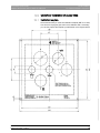
3.4.1 Installation template
We recommend that you order the installation template (REF 33 15 830)
from Sirona for laying the pipe ends in the installation field. If necessary,
you can also prepare the template yourself based on the diagram below.
Table for template

63 22 668 D3561
16 D3561.021.01.06.02 12.2014
3On-site installation Sirona Dental Systems GmbH
3.4Underfloor installation of supply lines Installation Requirements SINIUS / SINIUS CS / SINIUS TS
1 Water supply
Pipe 10x1 mm, corner valve outlet 3/8"
2 Compressed air supply
Pipe 10x1 mm, corner valve outlet 3/8"
3 Suction line
DN40 HT-PP ISO 8283-3
(polypropylene, inner diameter 36.5 mm)
4 Water drainage
DN40 HT-PP ISO 8283-3
(polypropylene, inner diameter 36.5 mm)
5 Installation pipe
DN40 HT-PP ISO 8283-3
(polypropylene, inner diameter 40 mm)
6 Control cable to relays for the
suction machine ( ),
call cable ( ),
Special function (#)
3 x 1.5 mm2 (quality as in the power cable)
7 Power supply
3x1.5 mm2
Circuit breaker: for 230 VAC: 16 A slow-blow
for 100 - 115 VAC: 20 A slow-blow
Recommended: Type B automatic circuit breaker
8 not connected
9 Installation pipe, inner diameter 50 mm
(or corresponding flat conduit) for the PC connection
%

63 22 668 D3561
D3561.021.01.06.02 12.2014 17
Sirona Dental Systems GmbH 3On-site installation
Installation Requirements SINIUS / SINIUS CS / SINIUS TS 3.4Underfloor installation of supply lines
båÖäáëÜ
3.4.2 Installation of the supply line in the termination panel
Supply lines for Teneo, Sinius
✔An installation template is available or was prepared.
1. Check the position of the supply lines against the installation template
as per the practice blueprint. Ensure that sufficient space is provided
between the lines and the walls; see "Scale 1:20". The center of the
hole in the floor must be 269 mm (10 5/8") from the foot of the
treatment center.
2. Lay the ends of the supply pipes, corner valves and lines as shown in
the illustrations.
ªThe top edge of the corner valves for air and water must not project
more than 60 mm from the top edge of the floor.
ªThe suction and drainage pipes must be flush with the top edge of the
floor (a deviation of +5 mm is permissible). The inner diameter of both
pipes is 36.5 mm.
ªThe electric lines must project by at least 500 mm.
ªThe supply lines are laid.
Ø 50 mm Ø 36,5 mm
>500mm
>20“
< 3/16“
< 5mm
< 60mm
< 2 3/8“
Ø 36,5 mm
3/8“

63 22 668 D3561
18 D3561.021.01.06.02 12.2014
3On-site installation Sirona Dental Systems GmbH
3.5Cleaning the air and water pipes Installation Requirements SINIUS / SINIUS CS / SINIUS TS
3.5 Cleaning the air and water pipes
Flushing the air and water pipes
NOTICE
Chips and other foreign materials could be flushed and/or blown into the
treatment center.
Metal chips can cause malfunctions of the pneumatic components. The
filters become clogged with foreign materials.
➢During installation, ensure that no chips or other foreign materials
enter the lines.
➢Flush the water lines.
➢Blow out the air lines.
➢Ensure that no more foreign materials can enter the lines after they
have been flushed or blown out.
10l
>30 sec
Versorgung durch den Fußboden
Supply through the floor
Alimentation à travers du plancher
Alimentación a través del suelo

63 22 668 D3561
D3561.021.01.06.02 12.2014 19
Sirona Dental Systems GmbH 3On-site installation
Installation Requirements SINIUS / SINIUS CS / SINIUS TS 3.6Underfloor installation of the PC connections
båÖäáëÜ
3.6 Underfloor installation of the PC connections
Depending on the prevailing local conditions, the existing cable set can
be installed in the cable duct of an underfloor installation by an installer.
Cable channel No. 9 is used for this purpose, see Installation
template [ → 15].
Cable set for Sinius
Cable set for PC connection with HDMI and USB cable for camera
SiroCam AF / AF+, digital
REF 63 29 655
Cable break
Running cables to the PC
HYBRID PC connection cables
Lines L343 (USB repeater), L339 (Ethernet), L406 (HDMI) and protective
ground wire. For PCs without a HDMI output, the Audio line is also
required.
To prevent transmission interference, ensure that the cables are not
crossed.
Laying PC connection cables, HYBRID
✔A cable duct is laid from the treatment center to the location of the PC.
✔Free length A of cables at the treatment center end: Length A = 600
mm
1. Pull the lines L343 (USB repeater), L339 (Ethernet), L406 (HDMI)
and protective ground wire of the treatment center through the cable
duct to the location of the PC C. For PCs without a HDMI output,
insert the Audio line. For the USB line L343 the TYPE A connector
must be on the PC side and the TYPE B connector on the chair side.
2. Save the accessory parts for final installation!
ªThe preparation of the connection for the underfloor installation of the
PC is completed.
Minimum PC requirements
NOTICE
Electric lines are susceptible to breakages.
Any kinks or twists in the cables could damage their wires. You must
then replace such cables.
➢Ensure that electrical lines do not become kinked or twisted.
C
A
IMPORTANT
Minimum requirements for PC
See document "Installation instructions and system requirements for PC
configuration," (REF 61 94 075 SIVISION digital.

63 22 668 D3561
20 D3561.021.01.06.02 12.2014
4Dimensions, technical data Sirona Dental Systems GmbH
4.1SINIUS dimensions, scale bar 1:20 Installation Requirements SINIUS / SINIUS CS / SINIUS TS
4Dimensions, technical data
4.1 SINIUS dimensions, scale bar 1:20
Dentist element with travel track
4.1.1 Dimensions of the treatment room
D
269
10 5/8”
1450
57”
1100
43 5/16”
2250
88 9/16”
410
16 1/8”
A
B
141
5 9/16”
600
23 5/8” C
ARecommended distances from cabinet or wall.
BCenter of the floor cut-out/installation area
CMinimum distance with tray and HELIODENT Plus
DHazard warning: The lamp installed here and the tray and
HELIODENT Plus have a swivel range which exceeds the
specified distances!
Page is loading ...
Page is loading ...
Page is loading ...
Page is loading ...
Page is loading ...
Page is loading ...
Page is loading ...
Page is loading ...
Page is loading ...
Page is loading ...
Page is loading ...
Page is loading ...
Page is loading ...
Page is loading ...
Page is loading ...
Page is loading ...
Page is loading ...
Page is loading ...
Page is loading ...
Page is loading ...
Page is loading ...
Page is loading ...
Page is loading ...
Page is loading ...
Page is loading ...
Page is loading ...
Page is loading ...
Page is loading ...
Page is loading ...
Page is loading ...
Page is loading ...
Page is loading ...
Page is loading ...
Page is loading ...
Page is loading ...
Page is loading ...
Page is loading ...
Page is loading ...
-
 1
1
-
 2
2
-
 3
3
-
 4
4
-
 5
5
-
 6
6
-
 7
7
-
 8
8
-
 9
9
-
 10
10
-
 11
11
-
 12
12
-
 13
13
-
 14
14
-
 15
15
-
 16
16
-
 17
17
-
 18
18
-
 19
19
-
 20
20
-
 21
21
-
 22
22
-
 23
23
-
 24
24
-
 25
25
-
 26
26
-
 27
27
-
 28
28
-
 29
29
-
 30
30
-
 31
31
-
 32
32
-
 33
33
-
 34
34
-
 35
35
-
 36
36
-
 37
37
-
 38
38
-
 39
39
-
 40
40
-
 41
41
-
 42
42
-
 43
43
-
 44
44
-
 45
45
-
 46
46
-
 47
47
-
 48
48
-
 49
49
-
 50
50
-
 51
51
-
 52
52
-
 53
53
-
 54
54
-
 55
55
-
 56
56
-
 57
57
-
 58
58


Ask a question and I''ll find the answer in the document
Finding information in a document is now easier with AI
Related papers
-
Sirona C3 Plus Operating Instructions Manual
-
-
-
-
-
-
-
Dentsply Sirona SIM MODULAR Operating Instructions Manual
-
Dentsply Sirona CEREC MC XL Premium Package Operating Instructions Manual
-
Other documents
-
Dentsply Sirona TENEO Operating instructions
-
DHP 1 Horsepower Owner's manual
-
-
 Air Techniques Monarch Lines Cleaner Owner's manual
-
 Sirona Dental Schick CDR PlusWire User manual
-
KaVo ESTETICA E70/E80 Vision Operating instructions
-
KaVo MASTERtorque LUX M9000 L / LS Operating instructions
-
-
-
Dentsply Sirona Axeos Operating instructions

