75W DMX512 & RDM LED Driver(constant voltage) 70230035
Function introduction
Important: Read All Instructions Prior to Installation
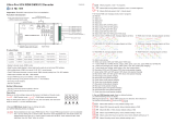
Digital display
• Built-in DMX512 interface, support RDM bi-directional communication
• 100-277VAC wide input voltage
• 4 DMX512 Addresses, 4 Channels Output . DMX channel quantity from 1CH~4CH settable
• To control single color, dual color, RGB/RGBW LED lighting
• PWM output resolution ratio 8bit , 16bit settable.
• Output PWM frequency from 500HZ ~ 30K HZ settable.
• Output dimming curve gamma value from 0.1 ~ 9.9 settable.
• Compatible with universal DMX512 consoles
• Class Ⅱ power supply, full isolated plastic case
• High power factor and efficiency
• Galvanic isolation
• IP20 rating, suitable for indoor LED lighting applications
• DO NOT install with power applied to device.
• DO NOT expose the device to moisture.
Safety & Warnings
MTBF
Dimension
Others
Over Current Yes, recovers automatically after fault condition is removed
Over Temperature
Protection
Yes, recovers automatically after fault condition is removed
Max. Case Temp. 80℃
Working Humidity
Working Temp.
Environment
-25 ~ +45℃ ℃
10% ~ 95% RH non-condensing
Storage Temp.
& Humidity -40 ~ +80 , 10% ~ 95% RH℃ ℃
Withstand Voltage I/P-O/P: 3.75KVAC
Isolation Resistance
Safety Standards
Safety &
EMC I/P-O/P: 100M Ohms / 500VDC / 25℃ / 70% RH
EMC Emission EN55015, EN61000-3-2, EN61000-3-3
EMC Immunity EN61547, EN61000-4-2,3,4,5,6,8,11, surge immunity Line-Line 1KV
Product Data
Voltage Range 100-277V AC
Power Factor (Typ.)
Efficiency (Typ.)
Frequency Range 50/60Hz
Input
Rated Power max. 75W
Output Max. Current
DC Voltage
Max. 3.12A/ch, ch1+ch2+ch3+ch4=3.12A
LED Channel 4
Voltage Tolerance ±1%
> 0.99 @ 100VAC, > 0.96 @ 230VAC
Total Harmonic
Distortion
AC Current (Typ.)
Inrush Current (Typ.)
Leakage Current
Standby Power
Consumption
COLD START Max. 2A at 230VAC
THD ≤ 15% (@ full load / 230VAC)
0.9A @ 100VAC, 0.39A @ 230VAC, 0.33A@277VAC
< 0.5mA /230VAC
< 0.5W
86% @ 230VAC full load
Control
Dimming Interface
Dimming Range
Dimming Method
0.1%-100%
DMX/RDM
Pulse Width Modulation
24V DC 244*64*32mm (L*W*H)
Dimming Curve Logarithmic, Linear
AC 100-277V
power input
DMX512 signal
input/output
Common Anode Output(+)
CH 1:R/WW output(-)
CH 2:G/CW output(-)
CH 3:B/WW output(-)
CH 4:W/CW output(-)
Back Ent er Up Dow n
DMX512&RDM LED Driver
LED
OUTPU T
N
L
NC
NC
NC
INPUT
100-2 77VAC
GND
D-
D+
1/R -
4/W -
2/G -
3/B -
D-
D+
DMX IN/ OUT
emc
300MHz
UL8750, CAN/CSA C22.2 No. 250.13-14,
ENEC EN61347-1, EN61347-2-13 approved
Operation
Button introduction
Up, Down button is for menu selection. After power on the decoder,
if keep on clicking Up button, you will find below menu on display:
188300H, MIL-HDBK-217F @ 230VAC at full load and 25℃
ambient temperature

DMX address is 001, CH03
DMX Console
Slider number
DMX channel
dp1.1 dp2.1
1for output
1 dimming
2for output 2
dimming
for output 1
micro dimming
dp4.3
for output 1
dimming
for output 2
dimming
3
4for output 2
micro dimming
for output 3,4
dimming
for output 2
dimming
dp5.3
for output 1
dimming
for output 2
dimming
5
6for output 3,4
micro dimming
for output 3,4
dimming strobe effects
for output 3,4
dimming
for output
1 dimming
for all output
master dimming
for output 3,4
dimming
for all output
master dimming
DMX address is 001, CH04
DMX Console
Slider number
DMX channel
dp1.1 dp2.1
1for output
1 dimming
2for output 2
dimming
for output 1
micro dimming
dp5.4
for output 1
dimming
for output 2
dimming
3
4for output 2
micro dimming
for output 3
dimming
for output 2
dimming
dp6.4
for output 1
dimming
for output 2
dimming
5
6for output 3
micro dimming
for all output
master dimming
for output 3
dimming
for all output
master dimming
for output 3
dimming
for output
1 dimming
for output 4
dimming
for output 3
dimming
for output 4
dimming
7
8for output 4
micro dimming
for output 4
dimming
strobe effects
for output 4
dimming
DMX address is 001, CH01
DMX Console
Slider number
DMX channel
dp1.1 dp2.1
1for all output
dimming
for all output
dimming
2No use for all output
micro dimming
DMX address is 001, CH02
DMX Console
Slider number
DMX channel
dp1.1 dp2.1
1for output
1&3 dimming
2for output 2,4
dimming
for output 1&3
micro dimming
dp3.2
for output 1&3
dimming
for output 2,4
dimming
for output
1&3 dimming
3
4for output 2,4
micro dimming
for all output
dimming
for output 2,4
dimming
Back Enter Up Down
XXX Means DMX address. fa ctory defaults setting is 001.
XX Means DMX channels quantity.
XX Means Bit (8bit or 16bit). factory defaults setting is 16bit
XX Means output PWM frequency. factory defaults setting is 1K HZ
XX Means output dimming curve gamma value, factory defaults setting is ga 1.5
XX Means Decoding mode, factory defaults setting is dp1.1
By holding button Back + Enter together at the same time over 5 seconds until the display go off,
it will restore default settings .
1. DMX address setting:
select menu , click button “Enter”, display flashes,then click or hold button “Up” / “Down”
to set DMX address (click is slow, hold is fast.), then click button“Back” to confirm.
XXX
2. DMX channel quantity setting:
Select menu , click button “Enter”, display flashes, then click button “Up” / “Down”
to set DMX channel quantity , then click button“Back” to confirm.
For example the DMX address is already set 001.
CH01=1 DMX address for all the output channels, which are all address 001.
CH02=2 DMX addresses , output 1&3 is address 001, output 2,4 is address 002
CH03=3 DMX addresses, output 1, 2 is address 001,002, output 3,4 is address 003
CH04=4 DMX addresses, output 1,2,3,4 is address 001,002,003,004
XX
3. PWM output resolution Bit setting:
select menu , click button “Enter”,display flashes, then click button “Up” / “Down”
to choose 08 or 16 bit, then click button“Back” to confirm.
XX
4. output PWM frequency setting:
select menu , click button “Enter”, display flashes,then click button “Up” / “Down”to choose 00~30,
then click button“Back” to confirm. 00=500HZ, 01=1kHZ, 02=2kHZ.....30=30kHZ.
XX
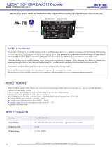
5. output dimming curve gamma value setting:
select menu , click button “Enter”, display flashes, then click or hold button “Up” / “Down”
to choose 0.1~9.9, then click button“Back” to confirm.
XX
1.0
1.5
2.5
3.5 6.5
0.90.9
0.8
gamma value
>1
<1
DMX value level
output
brightness
level
6. DMX decoding mode setting:
Select menu , click button “Enter”, display flashes, then click or hold button “Up” / “Down”to choose the
decoding mode, then click button“Back” to confirm.“dPxx” means the DMX address quantity used for control of
corresponding PWM output channel quantity. 1st “x” is DMX address quantity, 2nd “x” is PWM channel quantity.
Micro dimming: the micro dimming effect can only be visible when the dimming curve gamma value is set lower
than 1.4, and the lower the value is, the more visible the micro dimming effect will be.
XX
Restore to Factory Default Setting
Press and hold down both “Back” and “Enter” keys
until the digital display turns off, then release the
keys, system will reset and the digital display will
turn on again, all settings will be restored to
factory default.
Default settings are as follows:
DMX Address Code: a001
DMX Address Quantity: SW1=0: ch04, SW1=1:
ch03
PWM Resolution Mode: bt16
PWM Frequency: pf01
Gamma: ga1.5
Decoding Mode: dp1.1
The supported RDM PIDs are as follows:
DISC_UNIQUE_BRANCH
DISC_MUTE
DISC_UN_MUTE
DEVICE_INFO
DMX_START_ADDRESS
IDENTIFY_DEVICE
SOFTWARE_VERSION_LABEL
DMX_PERSONALITY
DMX_PERSONALITY_DESCRIPTION
SLOT_INFO
SLOT_DESCRIPTION
MANUFACTURER_LABEL
SUPPORTED_PARAMETERS
The data definitions for strobe channel
are as follows:
{0, 7},//undefined
{8, 65},//slow strobe-->fast strobe
{66, 71},//undefined
{72, 127},//slow push fast close
{128, 133},//undefined
{134, 189},//slow close fast push
{190, 195},//undefined
{196, 250},//random strobe
{251, 255},//undefined
XXX
DMX signal indicator : When DMX signal input is detected,
the indicator on the display following after turns on red
.

Wiring diagram
Back E nter Up Down
DMX512&RDM LED Driver
LED
OUT PUT
N
L
NC
NC
NC
INP UT
100 -277 VAC
GND
D-
D+
1/R-
4/W-
2/G-
3/B-
D-
D+
DMX I N/OUT
AC 100-277V input
V+ V+
R- R-
G- G-
B- B-
W- W- RGBW LE D Strip
DMX512
Master
AC 100-277V input
AC 100-277V input
CCT LED S trip
V+ V+
WW- WW-
CW- CW-
Singl e Color LED St rip
V+ V+
V- V-
Back E nter Up Down
DMX512&RDM LED Driver
LED
OUT PUT
N
L
NC
NC
NC
INP UT
100 -277 VAC
GND
D-
D+
1/R-
4/W-
2/G-
3/B-
D-
D+
DMX I N/OUT
Back E nter Up Down
DMX512&RDM LED Driver
LED
OUT PUT
N
L
NC
NC
NC
INP UT
100 -277 VAC
GND
D-
D+
1/R-
4/W-
2/G-
3/B-
D-
D+
DMX I N/OUT
244 mm
32 mm 64 mm
Fixing Screw Holes Fixing Screw Holes
Note: when mounting the driver, please choose any one of the three fixing screw holes to fix with a
screw at each end.
Product Dimension
Installation
/