Page is loading ...

DMX512 & RDM Decoder
DMX
Fema le
Sign al DMX Si gnal
Male
3
5
4
1
2
3
5
4
1
2
Pin1 :GND
Pin2 :D-
Pin3 :D+
DC IN PUT
Bac k Enter Up Dow n
DMX O K
Pin1 :Data +
Pin2 :Data -
Pin7 :GND
Pin8 :GND
12345678
DMX+ 10V RJ4 5
12345678
DMX in /outDMX in /out
V-
V+
+
6-
5-
4-
3-
2-
1-
LED O UTPUT
Sof tware
int erfac e
Ultra-Pro 6CH RDM DMX512 Decoder 70060055
Back Enter Up Down
Before you do other settings, please set the device to be Master or Decoder mode.
= DMX Decoder mode , = DMX Master mode(stand alone).
Keep on clicking Down button, to get run1 or run2, then click Enter, then click Down
button to choose 1 or 2, then click Back button.
I. For run2 DMX Master mode: After power on the device, if keep on clicking Up button,
you will find below menu on display:
• Master & decoder mode, RDM function
• Metal housing, digital display to show data directly, easily to set and show DMX address.
• With multiple kinds of DMX in/out ports: RJ 45, XLR , normal screws.
• Total 6 PWM output channels, common anode. DMX channel quantity 1CH or 6CH settable
• PWM output resolution ratio 8bit , 16bit settable.
• Output PWM frequency from 500Hz ~ 35KHz settable.
• Output dimming curve gamma value from 0.1 ~ 9.9 settable.
• Decoding mode settable.
• Galvanic isolation
Function introduction
Important: Read All Instructions Prior to Installation
Product Data
• DO NOT install with power applied to device.
• DO NOT expose the device to moisture.
Safety & Warnings
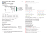
3/5 Pin male & female XLR terminal:
DMX512 signal input & output
2xRJ45 terminal:
DMX512 signal input & output
DC power input
Common Anode Output(+)
Digital display
Operation
Size(LxWxH)
187.7x85.3x41mm
Input Voltage Remarks
Output Current
12-24VDC Constant voltage6x(72-144)W
6x6A
Output Power
187.7x85.3x41mm
12-48VDC Constant current
6x(4.2-16.8)W
6x350mA
Means brightness for each output PWM channel. First 1 means PWM output channel 1 and it is selectable
from 1 to 6 by clicking “UP” or “Down” button. Second 01 means brightness level, click “Enter” button, the
display flashes, then click “UP” or “Down” button to select from 00-99-FL, which means 0%-99%-100%
brightness, then click “Back” button to confirm.
means chasing effects, total 4 effects selectable from 01-04. Click “Up” or “Down” button to select the menu,
then click “Enter” button to enter into the effect, then click “Up” or “Down” button to select from 01-04.
CA01: Fade-up (0%-100%) and fade-down (100%-0%) of output 1, then output 2, output 3, ……, output 5, output 6, then
simultaneously fade-up and fade-down of output 1, 2, 3, 4, 5, 6, then fade-up and down of output 1, ......, cycling chase
CA02: Fade-up (0%-100%) of output 1, then simultaneous fade-down (100%-0%) of output 1 and fade-up (0%-100%) of
output 2, simultaneous down of output 2 and up of output 3, ……, simultaneous down of output 4 and up of output 5,
simultaneous down of output 5 and up of output 6, simultaneous down of output 6 and up of output 1, then up of output
1, ……, cycling chase
CA03: Fade-up (0%-100%) of output 1, then output 2, output 3, ……, output 5, output 6, then simultaneously fade-up of
output 1, output 2, output 3, output 4, output 5 and output 6, then fade up of output 1, ……, cycling chase
CA04: Fade-down (100%-0%) of output 1, then output 2, output 3, ……, output 5, output 6, then simultaneously fade-
down of output 1, output 2, output 3, output 4, output 5, output 6, then fade-down of output 1, ……, cycling chase
means chasing speed, it is selectable from 01-09, 01 is the slowest, 09 is the fastest.
XXX Means DMX address. factory default setting is 001.
XX Means DMX channels quantity. factory default setting is CH06
XX Means Bit (8bit or 16bit). factory default setting is 16bit
XX Means output dimming curve gamma value, factory default setting is ga 1.5
XX Means Decoding mode, factory default setting is dp1.1
By pressing and holding button Back + Enter together at the same time over 5 seconds until the display go off, it
will restore to default settings .
II. For run1 DMX decoder mode: After select run1, if keep on clicking Up button,
you will find below menu on display:
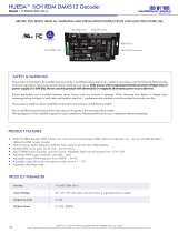
Wiring diagram
RGBW LED Str ip
V+ V+
W- W-
B- B-
G- G-
R- R-
CCT Color LED Strip
CW- CW-
WW- WW-
V+ V+
RGBW LED Strip
1.Work as Master mode
187.7x85.3x41mm
12-48VDC Constant current
6x(8.4-33.6)W
6x700mA
V- V+
12V/24V
CV PSU
V-
V+
OUTPUT
CH 6 output(-)
CH 5 output(-)
CH 4 output(-)
CH 3 output(-)
CH 2 output(-)
CH 1 output(-)
RGBW LED Str ip
V+ V+
W- W-
B- B-
G- G-
R- R-
CCT Color LED Strip
CW- CW-
WW- WW-
V+ V+
RGBW LED Strip
V- V+
12V/24V
CV PSU
V-
V+
OUTPUT
DMX512 & RDM Decoder
DMX
Fem ale
Sig nal D MX Si gna l
Mal e
3
5
4
1
2
3
5
4
1
2
Pin 1:G ND
Pin 2:D -
Pin 3:D +
DC INPUT
Back En ter Up Do wn
DMX OK
Pin 1:D ata +
Pin 2:D ata -
Pin 7:G ND
Pin 8:G ND
12345678
DMX +10V RJ 45
12345678
DMX i n/outDMX i n/out
V-
V+
+
6-
5-
4-
3-
2-
1-
LED OUTPUT
Softw are
inter face
Software interface
DMX signal indicator : When DMX signal input is detected, the indicator on the display following
after turns on red, the indicator will turn off and the character will flash if no DMX input detected.
XXX
XX Means output PWM frequency. factory default setting is 1K HZ

DMX512 & RDM Decoder
DMX
Fema le
Sign al DMX Si gnal
Male
3
5
4
1
2
3
5
4
1
2
Pin1 :GND
Pin2 :D-
Pin3 :D+
DC IN PUT
Bac k Enter Up Dow n
DMX O K
Pin1 :Data +
Pin2 :Data -
Pin7 :GND
Pin8 :GND
12345678
DMX+ 10V RJ4 5
12345678
DMX in /outDMX in /out
V-
V+
+
6-
5-
4-
3-
2-
1-
LED O UTPUT
Sof tware
int erfac e
2.Work as Decoder mode
5. output dimming curve gamma value setting :(Factory default is gA1.5)
select menu , click button “Enter”, display flashes, then click or hold button “Up” / “Down”
to choose 0.1~9.9, then click button“Back” to confirm.
XX
>1
<1
1.0
1.5
2.5
3.5 6.5
0.90.9
0.8
gamma value
DMX value level
output
brightness
level
6. DMX decoding mode setting :(Factory default is dP1.1)
Select menu , click button “Enter”, display flashes, then click or hold button “Up” / “Down”to choose the
decoding mode, then click button“Back” to confirm. “dPxx” means the DMX address quantity used for control of
corresponding PWM output channel quantity. 1st “x” is DMX address quantity, 2nd “x” is PWM channel quantity.
Fine dimming: the fine dimming effect can only be visible when the dimming curve gamma value is set lower than
1.4, and the lower the value is, the more visible the fine dimming effect will be.
XX
select menu , click button “Enter”,display flashes, then click button “Up” / “Down”
to choose 08 or 16 bit, then click button“Back” to confirm.
XX
3. PWM output resolution Bit setting :(Factory default is bt16, 16 bit)
1. DMX address setting :(Factory default is A001, address 001)
select menu , click button “Enter”, display flashes, then click or hold button “Up” / “Down”
to set DMX address (click is slow, hold is fast.), then click button“Back” to confirm.
XXX
2. DMX channel quantity setting :(Factory default is CH06, 6 channels)
Select menu , click button “Enter”, display flashes, then click button “Up” / “Down”
to set DMX channel quantity , then click button “Back” to confirm.
For example the DMX address is already set 001.
CH01=1 DMX address for all the output channels, which are all address 001.
CH06=6 DMX addresses, output 1, 2, 3, 4, 5, 6 is address 001, 002, 003, 004, 005, 006.
XX
The data definitions for strobe channel
are as follows:
{0, 7},//undefined
{8, 65},//slow strobe-->fast strobe
{66, 71},//undefined
{72, 127},//slow push fast close
{128, 133},//undefined
{134, 189},//slow close fast push
{190, 195},//undefined
{196, 250},//random strobe
{251, 255},//undefined
Restore to Factory Default Setting
Press and hold down both “ ” and “Enter” keys until
then release the keys, system will reset and the digital display will turn on again, all
settings will be restored to factory default.
Default settings are as follows:
DMX Address Code: a001
DMX Address Quantity: SW1=0: ch06, SW1=1: ch01
PWM Resolution Mode: bt16
PWM frequency: F010
Gamma: ga1.5
Decoding Mode: dp1.1
Back the digital display turns off,
The supported RDM PIDs are as follows:
DISC_UNIQUE_BRANCH
DISC_MUTE
DISC_UN_MUTE
DEVICE_INFO
DMX_START_ADDRESS
IDENTIFY_DEVICE
SOFTWARE_VERSION_LABEL
DMX_PERSONALITY
DMX_PERSONALITY_DESCRIPTION
SLOT_INFO
SLOT_DESCRIPTION
MANUFACTURER_LABEL
SUPPORTED_PARAMETERS
DMX address is 001, CH06
DMX Console
Slider number
DMX channel
dp1.1 dpA.1 dpA.2 dpA.3 dpA.4 dpA.6
1 dimming
for output
for output 2
dimming
for output 3
dimming
for output 4
dimming
for output 5
dimming
for output
1 dimming
for output 2
dimming
for output 3
dimming
for output 4
dimming
for output 5
dimming
1
2
3
4
5
6
7
8
9
10
1for all outputs
dimming
for all outputs
dimming
2No use for all outputs
fine dimming
DMX address is 001, CH01
DMX Console
Slider number
DMX channel
dp1.1 dp2.1
for output 6
dimming
for output 6
dimming
for output
1 dimming
for output 2
dimming
for outputs 1&2
master dimming
for output
3 dimming
for output
4 dimming
for outputs 3&4
master dimming
for output
1 dimming
for output 2
dimming
for output 3
dimming
for outputs 1&3
master dimming
for output 4
dimming
for output 5
dimming
for output
1 dimming
for output 2
dimming
for output 3
dimming
for output 4
dimming
for output 5
dimming
for outputs 1&4
master dimming
for outputs 1+2
color tuning
for outputs 1&2
master dimming
for outputs 3+4
color tuning
for outputs 3&4
master dimming
for outputs 5+6
color tuning
for outputs 5&6
master dimming
RGBW LED Str ip
V+ V+
W- W-
B- B-
G- G-
R- R-
CCT Color LED Strip
CW- CW-
WW- WW-
V+ V+
RGBW LED Strip
V- V+
12V/24V
CV PSU
V-
V+
OUTPUT
DMX Master
Console
for all outputs
master dimming
strobe effects
for output
5 dimming
for output
6 dimming
for outputs 5&6
master dimming
for output 6
dimming
for outputs 4&6
master dimming
for output 6
dimming
for outputs 5&6
master dimming
No use
No use
strobe effects
No use No use
4. output PWM frequency setting :(Factory default is PF01, 1kHZ)
select menu , click button “Enter”, display flashes,then click
button “Up” / “Down”to choose 00~35, then click button“Back” to confirm.
00=500HZ, 01=1kHZ, 02=2kHZ.....25=25kHZ, 35=35kHZ.
XX
dp7.1
for output
1 dimming
for output 2
dimming
for output 3
dimming
for output 4
dimming
for output 5
dimming
for output 6
dimming
for all outputs
master dimming
No use
No use
No use No use
No use
No use
Assign DMX address through RDM
When using RDM to assign DMX address to the device, the digital display
will flash and the connected lights will also flash at the same frequency.
Once the display stops flashing, the connected light also stops flashing.
/