4. output PWM frequency setting:
select menu , click button “Enter”, display flashes,then click button “Up” / “Down”to choose 00~30,
then click button“Back” to confirm. 00=500HZ, 01=1kHZ, 02=2kHZ.....30=30kHZ.
XX
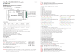
5. output dimming curve gamma value setting:
select menu , click button “Enter”, display flashes, then click or hold button “Up” / “Down”
to choose 0.1~9.9, then click button“Back” to confirm.
XX
>1
<1
1.0
1.5
2.5
3.5 6.5
0.90.9
0.8
gamma value
DMX value level
output
brightness
level
6. DMX decoding mode setting:
Select menu , click button “Enter”, display flashes, then click or hold button “Up” / “Down”
to choose the decoding mode, then click button“Back” to confirm. “dPxx” means the DMX address quantity
used for control of corresponding PWM output channel quantity. 1st “x” is DMX address quantity, 2nd “x” is
PWM channel quantity.
Micro dimming: the micro dimming effect can only be visible when the dimming curve gamma value is set lower
than 1.4, and the lower the value is, the more visible the micro dimming effect will be.
XX
DMX address is 001, CH01
DMX Console
Slider number
DMX channel
dp1.1 dp2.1
1for all output
dimming
for all output
dimming
2No use for all output
micro dimming
DMX address is 001, CH02
DMX Console
Slider number
DMX channel
dp1.1 dp2.1
1for output
1&3 dimming
2for output 2,4
dimming
for output 1&3
micro dimming
dp3.2
for output 1&3
dimming
for output 2,4
dimming
for output
1&3 dimming
3
4for output 2,4
micro dimming
for all output
dimming
for output 2,4
dimming
DMX address is 001, CH03
DMX Console
Slider number
DMX channel
dp1.1 dp2.1
1for output
1 dimming
2for output 2
dimming
for output 1
micro dimming
dp4.3
for output 1
dimming
for output 2
dimming
3
4for output 2
micro dimming
for output 3,4
dimming
for output 2
dimming
dp5.3
for output 1
dimming
for output 2
dimming
5
6for output 3,4
micro dimming
for output 3,4
dimming strobe effects
for output 3,4
dimming
for output
1 dimming
for all output
master dimming
for output 3,4
dimming
for all output
master dimming
DMX address is 001, CH04
DMX Console
Slider number
DMX channel
dp1.1 dp2.1
1for output
1 dimming
2for output 2
dimming
for output 1
micro dimming
dp5.4
for output 1
dimming
for output 2
dimming
3
4for output 2
micro dimming
for output 3
dimming
for output 2
dimming
dp6.4
for output 1
dimming
for output 2
dimming
5
6for output 3
micro dimming
for all output
master dimming
for output 3
dimming
for all output
master dimming
for output 3
dimming
for output
1 dimming
for output 4
dimming
for output 3
dimming
for output 4
dimming
7
8for output 4
micro dimming
for output 4
dimming
strobe effects
for output 4
dimming
3. PWM output resolution Bit setting:
select menu , click button “Enter”,display flashes, then click button “Up” / “Down”
to choose 08 or 16 bit, then click button“Back” to confirm.
XX
The data definitions for strobe
channel are as follows:
{0, 7},//undefined
{8, 65},//slow strobe-->fast strobe
{66, 71},//undefined
{72, 127},//slow push fast close
{128, 133},//undefined
{134, 189},//slow close fast push
{190, 195},//undefined
{196, 250},//random strobe
{251, 255},//undefined
Restore to Factory Default Setting
Press and hold down both “ ” and “Enter” keys until
digital display turns off, then release the keys, system will reset
and the digital display will turn on again, all settings will be
restored to factory default.
Default settings are as follows:
DMX Address Code: a001
DMX Address Quantity: SW1=0: ch04, SW1=1: ch03
PWM Resolution Mode: bt16
PWM Frequency: pf01
Gamma: ga1.5
Decoding Mode: dp1.1
Back the
The supported RDM PIDs are as follows:
DISC_UNIQUE_BRANCH
DISC_MUTE
DISC_UN_MUTE
DEVICE_INFO
DMX_START_ADDRESS
IDENTIFY_DEVICE
SOFTWARE_VERSION_LABEL
DMX_PERSONALITY
DMX_PERSONALITY_DESCRIPTION
SLOT_INFO
SLOT_DESCRIPTION
MANUFACTURER_LABEL
SUPPORTED_PARAMETERS
Back
Button introduction
Up, Down button is for menu selection.After power on the decoder,
if keep on clicking Up button, you will find below menu on display:
By holding button Back + Enter together at the same time over 5 seconds until the display go off,
it will restore default settings .
Enter Up Down
XXX Means DMX address. fa ctory defaults setting is 001.
XX Means DMX channels quantity.
XX Means Bit (8bit or 16bit). factory defaults setting is 16bit
XX Means output PWM frequency. factory defaults setting is 1K HZ
XX Means output dimming curve gamma value, factory defaults setting is ga 1.5
XX Means Decoding mode, factory defaults setting is dp1.1
1. DMX address setting:
select menu , click button “Enter”, display flashes,then click or hold button “Up” / “Down”
to set DMX address (click is slow, hold is fast.), then click button“Back” to confirm.
XXX
2. DMX channel quantity setting:
Select menu , click button “Enter”, display flashes, then click button “Up” / “Down”
to set DMX channel quantity , then click button“Back” to confirm.
For example the DMX address is already set 001.
CH01=1 DMX address for all the output channels, which are all address 001.
CH02=2 DMX addresses , output 1&3 is address 001, output 2,4 is address 002
CH03=3 DMX addresses, output 1, 2 is address 001,002, output 3,4 is address 003
CH04=4 DMX addresses, output 1,2,3,4 is address 001,002,003,004
XX
DMX signal indicator :: When DMX signal input is detected, the indicator on
the display following after turns on red .
XXX