Page is loading ...

Ultra-Pro 5CH RDM DMX512 Decoder
Back Enter Up Down
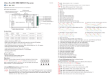
Before you do other settings, please set the device to be Master or Decoder mode.
= DMX Decoder mode , = DMX Master mode(stand alone).
Keep on clicking Down button, to get run1 or run2, then click Enter, then click Down
button to choose 1 or 2, then click Back button.
I. For run2 DMX Master mode: Keep on clicking Up button,
you will find following menus on display:
XXX Means programs , total 1~31 programs.
XX Means RGB running effect’s brightness, total 1~8 levels brightness
X Means effect play speed. total 1~9 levels speed.
• Metal housing, digital display to show data directly, easily to set and show DMX address.
• With multiple kinds of DMX in/out ports: RJ 45, XLR , normal screws.
• Total 5 PWM output channels, common anode. DMX channel quantity from 1CH~5CH settable
• PWM output resolution ratio 8bit , 16bit settable.
• Master & decoder mode, RDM function
• Output dimming curve gamma value from 0.1 ~ 9.9 settable.
• Output PWM frequency from 500HZ ~ 35K HZ settable.
• Decoding mode settable.
• Galvanic isolation
Function introduction
Important: Read All Instructions Prior to Installation
Product Data
• DO NOT install with power applied to device.
• DO NOT expose the device to moisture.
Safety & Warnings
2 groups Plug in type terminal:
DMX512 signal input & output
Size(LxWxH)
164x73x38mm
DMX512 & RDM Decoder
Pin1: Da ta+
Pin2: Da ta-
Pin7: GN D
Pin8: GN D
12345678
DMX Sig na l
Femal e
DMX Sig na l
Male
DMX Sig na l
RJ45
3
2
V-
V-
V+
V+
1/R-
2/G-
3/B-
4/W1-
5/W2-
Back Enter Up Down
D+
D-
D+
D-
GND
1
3
21
12345678
Pin1: GN D
Pin2: D-
Pin3: D+
Pin1: GN D
Pin2: D-
Pin3: D+
DMX in/ ou t
DC Power
input
DMX in/ ou tDMX in/ ou t
3/5 Pin male & female XLR terminal:
DMX512 signal input & output
2xRJ45 terminal:
DMX512 signal input & output
DC power input
Common Anode Output(+)
CH 1:R/WW output(-)
CH 2:G/CW output(-)
CH 3:B/WW output(-)
CH 4:W/CW output(-)
CH 5:W/WW output(-)
Input
Voltage Remarks
Output
Current
12-24VDC Constant voltage
5x(96-192)W
5x8A
Output
Power
Digital display
Operation
164x73x38mm
12-48VDC Constant current
5x(4.2-16.8)W
5x350mA
Means brightness for each output PWM channel. First 1 means PWM output channel 1 and it is selectable
from 1 to 5 by clicking “UP” or “Down” button. Second 01 means brightness level, click “Enter” button, the
display flashes, then click “UP” or “Down” button to select from 00-99-FL, which means 0%-99%-100%
brightness, then click “Back” button to confirm.
164x73x38mm
12-48VDC Constant current
5x(8.4-33.6)W
5x700mA
Protection
Short circuit
Short circuit
Short circuit
P-XX means RGB color changing modes, total 31 programs:
00- RGB off
01- Static red
02- Static green
03- Static blue
04- Static yellow (50% red+50% green)
05- Static orange (75% red+25% green)
06- Static cyan (50% green+50% blue)
07- Static purple (50% blue+50% red)
08- Static white (100% red+100% green+100% blue)
09- Any two colors of RGB mix fade, changing diagram as follow: 10- RGB colors mix fade, changing diagram as follow:
11- RGB FADE OUT & FADE IN, changing diagram as follow: 12- RGB jump changing, changing diagram as follow:
13- RGB FADE IN, changing diagram as follow: 14- RGB FADE OUT, changing diagram as follow:
15- RGB 3 colors strobe
16- White color strobe (100% red+100% green+100% blue)
17- 7 colors FADE OUT & FADE IN (red, orange, yellow, green, cyan, blue, purple FADE OUT & FADE IN)
18- 7 colors jump changing (red, orange, yellow, green, cyan, blue, purple jump changing)
19- 7 colors strobe (red, orange, yellow, green, cyan, blue, purple strobe)
20- Red-white (100% red+100% green+100% blue) circle gradual changing
21- Green-white (100% red+100% green+100% blue) circle gradual changing
22- Blue-white (100% red+100% green+100% blue) circle gradual changing
23- Red-orange circle gradual changing
24- Red-purple circle gradual changing
25- Green-yellow circle gradual changing
26- Green-cyan circle gradual changing
27- Blue-purple circle gradual changing
28- Blue-cyan circle gradual changing
29- Red-yellow-green circle gradual changing
30- Red-purple-blue circle gradual changing
31- Green-cyan-blue circle gradual changing
XXX Means DMX address. factory default setting is 001.
XX Means DMX channels quantity. factory default setting is Ch05.
XX Means Bit (8bit or 16bit). factory default setting is 16bit.
XX Means output PWM frequency. factory default setting is 1K HZ.
XX Means output dimming curve gamma value, factory default setting is ga 1.5.
II. For run1 DMX decoder mode: Keep on clicking Up button,
you will find following menus on display:
70060044-HD
DMX signal indicator : When DMX signal input is detected, the indicator on the display following after turns
on red , if there is no DMX signal input, the indicator will not turn on, and the character will flash.
XXX
you will get this after power on the decoder, it means this decoder supports firmware OTA update function.

By holding button Back + Enter together at the same time over 5 seconds until the display goes off,
it will restore to default settings.
>1
<1
1.0
1.5
2.5
3.5 6.5
0.90.9
0.8
gamma value
DMX value level
output
brightness
level
7. DMX decoding mode setting:
Select menu , click button “Enter”, display flashes, then click or hold button “Up” / “Down”to choose the
decoding mode, then click button“Back” to confirm. “dPxx” means the DMX address quantity used for control of
corresponding PWM output channel quantity. 1st “x” is DMX address quantity, 2nd “x” is PWM channel quantity.
Fine dimming: the fine dimming effect can only be visible when the dimming curve gamma value is set lower than
1.4, and the lower the value is, the more visible the fine dimming effect will be.
XX
DMX address is 001, CH03
DMX Console
Slider number
DMX channel
dp1.1 dp2.1
1for output
1 dimming
2for output 2
dimming
for output 1
fine dimming
dp4.3
for output 1
dimming
for output 2
dimming
3for output 3,4&5for output 2
dp5.3
for output 1
dimming
for output 2
dimming
for output 3,4
for output
1 dimming
for output 3,4&5
1for all output
dimming
for all output
dimming
2No use for all output
fine dimming
DMX address is 001, CH02
DMX Console
Slider number
DMX channel
dp1.1 dp2.1
1for output
1&3 dimming
2for output 2,4
&5 dimming
for output 1&3
fine dimming
dp3.2
for output 1&3
dimming
for output 2,4
&5 dimming
for output
1&3 dimming
3
4for output 2,4&5
fine dimming
for all output
dimming
for output 2,4
&5 dimming
DMX address is 001, CH01
DMX Console
Slider number
DMX channel
dp1.1 dp2.1
V- V+
12V/24V
CV PSU
V-
V+
OUTP UT
RGBW LED S tr ip
W- W-
B- B-
G- G-
R- R-
V+ V+
Single Color LED Strip
V- V-
V+ V+
RGBW LED Strip
1.Work as Master mode
DMX Master
Console
2.Work as Decoder mode
DMX512 & RDM Decoder
Pin 1:Da ta+
Pin 2:Da ta-
Pin 7:GN D
Pin 8:GN D
12345678
DMX S ignal
Fem ale
DMX S ignal
Mal e
DMX S ignal
RJ4 5
3
2
V-
V-
V+
V+
1/R -
2/G -
3/B -
4/W 1-
5/W 2-
Bac k Ent er Up Down
D+
D-
D+
D-
GND
1
3
21
12345678
Pin 1:GN D
Pin 2:D-
Pin 3:D+
Pin 1:GN D
Pin 2:D-
Pin 3:D+
DMX i n/out
DC Po wer
inp ut
DMX i n/outDMX i n/out
V- V+
12V/24V
CV PSU
V-
V+
OUTP UT
RGBW LED S tr ip
W- W-
B- B-
G- G-
R- R-
V+ V+
Single Color LED Strip
V- V-
V+ V+
RGBW LED Strip
V- V+
12V/24V
CV PSU
V-
V+
OUTPUT
RGBW LED Strip
W- W-
B- B-
G- G-
R- R-
V+ V+
Single Co lo r LE D Strip
V- V-
V+ V+
RGBW LED St ri p
Note: 1) the terminal blocks used for the input have two spaces for Voltage + and two spaces for GND which
allow for the huge current capability this unit has 5 X 8A = 40 AMPS of power!
2) Please make sure that the stripped wires are fully inserted into the terminal blocks and screws are tightened!
Wiring diagram
2. DMX address setting:
select menu , click button “Enter”, display flashes,then click or hold button “Up” / “Down”
to set DMX address (click is slow, hold is fast.), then click button“Back” to confirm.
XXX
XX Means Decoding mode, factory default setting is dp1.1
Run the OTA tool RS485-OTW on the computer, select the correct communication port “USB-
SERIAL” , baudrate “250000”, and data bit “9”, use default settings for other configurations. Then
click “file” button to select the new firmware from the computer, then click “Open Port”, the firmware
will be loaded. Then click “Download Firmware”, the right side state column of the OTA tool will
show “send link”. Then power on the decoders before “wait erase” displaying on the state column,
the digital display of the decoders will show . Then “wait erase” will show on the state
column, which means the updating starts. Then the OTA tool starts writing data to the decoders, the
state column will show the progress, once writing data finishes, the digital display of the decoders
will flash , which means firmware updated successfully.
1. Firmware OTA update:
This function can be used when there is a firmware update from the manufacturer, the update can
be executed through a Windows computer and an USB to serial port converter, the converter will
connect the computer and the decoder’s hard wire DMX port. A software RS485-OTW on the
computer will be used to push the firmware to the decoder.
Connect the computer and the decoder through the USB to serial port converter, if you need to
update multiple decoders’ firmware, connect the converter to first decoder’s DMX port, then
connect other decoders to the first decoder in daisy chain through the DMX port. Please do not
power on the decoders.
select menu , click button “Enter”, display flashes, then click or hold button “Up” / “Down”
to choose 0.1~9.9, then click button“Back” to confirm.
XX
5. output PWM frequency setting:
select menu , click button “Enter”, display flashes,then click button “Up” / “Down”to choose 00~35,
then click button“Back” to confirm. 00=500HZ, 01=1kHZ, 02=2kHZ.....25=25kHZ, 35=35kHZ.
XX
6. output dimming curve gamma value setting:
select menu , click button “Enter”,display flashes, then click button “Up” / “Down”
to choose 08 or 16 bit, then click button“Back” to confirm.
XX
4. PWM output resolution Bit setting:
3. DMX channel quantity setting:
Select menu , click button “Enter”, display flashes, then click button “Up” / “Down”
to set DMX channel quantity , then click button“Back” to confirm.
For example the DMX address is already set 001.
CH01=1 DMX address for all the output channels, which are all address 001.
CH02=2 DMX addresses , output 1&3 is address 001, output 2,4&5 is address 002
CH03=3 DMX addresses, output 1, 2 is address 001,002, output 3,4&5 is address 003
CH04=4 DMX addresses, output 1,2,3 is address 001,002,003, output 4&5 is address 004
CH05=5 DMX addresses, output 1,2,3,4,5 is address 001,002,003,004,005.
XX
dimmingdimming&5 dimming dimming

Short circuit protection
If short circuit of the connected load is detected, the display will flash to alarm and the load will be forced to
open circuit status. Once the fault is removed, the decoder will recover after re-powered on.
38 mm
164 mm
151 mm
73 mm
Product Dimension
DMX address is 001, CH05
DMX Console
Slider number
DMX channel
dp1.1 dp2.1
1for output
1 dimming
2for output 2
dimming
for output 1
fine dimming
dp6.5
for output 1
dimming
for output 2
dimming
3
4for output 2
fine dimming
for output 3
dimming
for output 2
dimming
dp7.5
for output 1
dimming
for output 2
dimming
5
6for output 3
fine dimming
for output 5
dimming
for output 3
dimming
for output 5
dimming
for output 3
dimming
for output
1 dimming
for output 4
dimming
for output 3
dimming
for output 4
dimming
7
8for output 4
fine dimming
for output 4
dimming
for all output
master dimming
for output 4
dimming
for output 5
for output 5
dimming
for all output
master dimming
strobe effects
9
10 for output 5
fine dimming
dimming
The data definitions for strobe channel
are as follows:
{0, 7},//undefined
{8, 65},//slow strobe-->fast strobe
{66, 71},//undefined
{72, 127},//slow push fast close
{128, 133},//undefined
{134, 189},//slow close fast push
{190, 195},//undefined
{196, 250},//random strobe
{251, 255},//undefined
Restore to Factory Default Setting
PWM Resolution Mode: bt16
Press and hold down both “Back” and “Enter” keys
until the digital display turns off, then release the
keys, system will reset and the digital display will
turn on again, all settings will be restored to factory
default.
Default settings are as follows:
DMX Address Code: a001
DMX Address Quantity: SW1=0: ch05, SW1=1:
ch04
PWM Frequency: pf01
Gamma: ga1.5
Decoding Mode: dp1.1
The supported RDM PIDs are as follows:
DISC_UNIQUE_BRANCH
DISC_MUTE
IDENTIFY_DEVICE
DISC_UN_MUTE
DEVICE_INFO
DMX_START_ADDRESS
CURVE_DESCRIPTION
DMX_PERSONALITY
CURVE
SOFTWARE_VERSION_LABEL
DMX_PERSONALITY_DESCRIPTION
MODULATION_FREQUENCY
SLOT_INFO
MANUFACTURER_LABEL
MODULATION_FREQUENCY_DESCRIPTION
SLOT_DESCRIPTION
SUPPORTED_PARAMETERS
6fine dimming
7
8for output 4&5
fine dimming
for output 4
&5 dimming
strobe effects
5
for output 3
for all output
master dimming
for output 3
dimming
for all output
master dimming
When using RDM to discover the device, the digital display will flash and the connected lights will also flash at
the same frequency to indicate. Once the display stops flashing, the connected light also stops flashing.
RDM Discovery Indication:
4for output 2
fine dimming
for output 4&5
dimming
for output 4&5
dimming
for output 4&5
dimming
DMX address is 001, CH04
DMX Console
Slider number
DMX channel
dp1.1 dp2.1
1for output
1 dimming
2for output 2
dimming
for output 1
fine dimming
dp5.4
for output 1
dimming
for output 2
dimming
3for output 3
dimming
for output 2
dimming
dp6.4
for output 1
dimming
for output 2
dimming
for output 3
dimming
for output
1 dimming
for output 3
dimming
5
6for output 3,4&5
fine dimming
&5 dimming strobe effects
4for output 2
fine dimming
for output 3,4
for all output
master dimming
for all output
master dimming
/