Page is loading ...

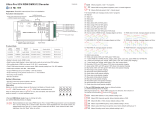
Common Anode Output(+)
Common Anode Output(+)
CH 1:R/WW output(-)
CH 2:G/CW output(-)
CH 3:B/WW output(-)
CH 4:W/CW output(-)
DMX512 signal input
200W DMX512 & RDM LED Driver(constant voltage) 70230028
Function introduction
Important: Read All Instructions Prior to Installation
AC 100-277V
power input Digital display
MTBF
Others
Over Current Yes, recovers automatically after fault condition is removed
Over Temperature
Protection
Yes, recovers automatically after fault condition is removed
Max. Case Temp. 85℃
Working Humidity
Working Temp.
Environment
-20℃ ~ +45℃
10% ~ 95% RH non-condensing
Storage Temp.
& Humidity -40℃ ~ +80℃, 10% ~ 95% RH
Withstand Voltage I/P-O/P: 3.75KVAC
Isolation Resistance
Safety Standards
Safety &
EMC I/P-O/P: 100M Ohms / 500VDC / 25℃ / 70% RH
EMC Emission EN55015, EN61000-3-2, EN61000-3-3
EMC Immunity EN61547, EN61000-4-2,3,4,5,6,8,11, surge immunity Line-Line 1KV
Product Data
Voltage Range 100-277V AC
Power Factor (Typ.)
Efficiency (Typ.)
Frequency Range 50/60Hz
Input
Rated Power max. 200W
Output
Max. Current
DC Voltage
Max. 8.3A/ch,
ch1+ch2+ch3+ch4=16.6A
24V DC12V DC
Max. 4.1A/ch,
ch1+ch2+ch3+ch4=8.4A
LED Channel 4
Voltage Tolerance ±1%
> 0.98 @ 230VAC
Total Harmonic
Distortion
AC Current (Typ.)
93% @ 230VAC full load
THD ≤ 15% (@ full load / 230VAC)
2.3A @ 100VAC, 1A @ 230VAC, 0.9A@277VAC
Leakage Current
Standby Power
Consumption
< 0.5mA /230VAC
< 1W
Control
Dimming Interface
Dimming Range
Dimming Method
0.1%-100%
DMX/RDM
Pulse Width Modulation
Dimming Curve Linear, Logarithmic
• IP20 rating, suitable for indoor LED lighting applications
• DMX512(2008), DMX512-A and RDM V1.0 (E1.20 – 2006 ESTA Standard)
• Enable to set DMX address, DMX channel quantity, PWM output resolution (8 bit or 16 bit)
• Compliant with Safety Extra Low Voltage standard
• Enable to set PWM output frequency, GAMMA ray dimming curve value and DMX decoding mode
• Built-in DMX dimming interface
• Over load, over temperature protection
• 5 years warranty
• Dimmable LED driver with rectangle metal case
• 4 channels 12/24VDC constant voltage output
• Class 1 power supply, full isolated metal case
• Built-in two-stage active PFC function
• PF > 0.98, Efficiency > 93%
• Output PWM frequency from 500HZ ~ 35K HZ settable.
• DO NOT expose the device to moisture.
• DO NOT install with power applied to the device.
Safety & Warnings
UL8750, CAN/CSA C22.2 No. 250.13-14,
ENEC EN61347-1, EN61347-2-13 approved
UpBack En ter Down
L
N
AC IN PUT
FG 4 -
GND
D+
D-
D+
D-
1-
2-
3-
LED O UTPUT
DMX 512 SIG NAL
200W DMX512 & RDM Dimmable Driver
(AWG2 0-14 )
(0.2 4-0. 28in )
SEC:
Outp ut Voltage=24VDC
Irate d=1x4.16A/2x4.16 A/
3x2. 75A/4x2.0 8A
Prat ed=1x100W/2x100W /
3x66 W/4x50W
INPU T:
100- 240V~ 2.3A 50/60Hz
277V ~ 0.806A 50/60Hz
(277 V~for North America onl y)
NC=Non e co nn ect Suitable for Damp Loc at io ns (CONVIENT AUX EMPLACEMENTS HUMI DE S)
E493567
ta
λ:>0.95 @230VAC
85
45
(AWG1 8-14 )
(0.5 5-0. 86in )
NC
NC
Inrush Current (Typ.) COLD START Max. 65A at 230VAC
emc
300MHz
185900H, MIL-HDBK-217F @ 230VAC at full load and 25℃
ambient temperature
Back Enter Up Down
Before you do other settings, please set the device to be Master or Decoder mode.
= DMX Decoder mode , = DMX Master mode(stand alone).
Keep on clicking Down button, to get run1 or run2, then click Enter, then click Down
button to choose 1 or 2, then click Back button.
I. For run2 DMX Master mode: Keep on clicking Up button,
you will find following menus on display:
Operation
Means brightness for each output PWM channel. First 1 means PWM output channel 1 and it is selectable
from 1 to 5 by clicking “UP” or “Down” button. Second 01 means brightness level, click “Enter” button, the
display flashes, then click “UP” or “Down” button to select from 00-99-FL, which means 0%-99%-100%
brightness, then click “Back” button to confirm.

XXX Means programs , total 1~31 programs.
XX Means RGB running effect’s brightness, total 1~8 levels brightness
X Means effect play speed. total 1~9 levels speed.
P-XX means RGB color changing modes, total 31 programs:
00- RGB off
01- Static red
02- Static green
03- Static blue
04- Static yellow (50% red+50% green)
05- Static orange (75% red+25% green)
06- Static cyan (50% green+50% blue)
07- Static purple (50% blue+50% red)
08- Static white (100% red+100% green+100% blue)
09- Any two colors of RGB mix fade, changing diagram as follow: 10- RGB colors mix fade, changing diagram as follow:
11- RGB FADE OUT & FADE IN, changing diagram as follow: 12- RGB jump changing, changing diagram as follow:
13- RGB FADE IN, changing diagram as follow: 14- RGB FADE OUT, changing diagram as follow:
15- RGB 3 colors strobe
16- White color strobe (100% red+100% green+100% blue)
17- 7 colors FADE OUT & FADE IN (red, orange, yellow, green, cyan, blue, purple FADE OUT & FADE IN)
18- 7 colors jump changing (red, orange, yellow, green, cyan, blue, purple jump changing)
19- 7 colors strobe (red, orange, yellow, green, cyan, blue, purple strobe)
20- Red-white (100% red+100% green+100% blue) circle gradual changing
21- Green-white (100% red+100% green+100% blue) circle gradual changing
22- Blue-white (100% red+100% green+100% blue) circle gradual changing
23- Red-orange circle gradual changing
24- Red-purple circle gradual changing
25- Green-yellow circle gradual changing
26- Green-cyan circle gradual changing
27- Blue-purple circle gradual changing
28- Blue-cyan circle gradual changing
29- Red-yellow-green circle gradual changing
30- Red-purple-blue circle gradual changing
31- Green-cyan-blue circle gradual changing
XXX Means DMX address. factory default setting is 001.
XX Means DMX channels quantity. factory default setting is Ch04
XX Means Bit (8bit or 16bit). factory default setting is 16bit
XX Means output PWM frequency. factory default setting is 1K HZ
XX Means output dimming curve gamma value, factory default setting is ga 1.5
II. For run1 DMX decoder mode: Keep on clicking Up button,
you will find following menus on display:
DMX signal indicator : When DMX signal input is detected, the indicator on the display following after turns
on red , if there is no DMX signal input, the indicator will not turn on, and the character will flash.
XXX
you will get this after power on the decoder, it means this decoder supports firmware OTA update function.
By holding button Back + Enter together at the same time over 5 seconds until the display goes off,
it will restore to default settings.
1.Work as Master mode
2.Work as Decoder mode
Note: Please make sure that the stripped wires are fully inserted into the terminal blocks and screws are
tightened!
Wiring diagram
2. DMX address setting:
select menu , click button “Enter”, display flashes,then click or hold button “Up” / “Down”
to set DMX address (click is slow, hold is fast.), then click button“Back” to confirm.
XXX
XX Means Decoding mode, factory default setting is dp1.1
Run the OTA tool RS485-OTW on the computer, select the correct communication port “USB-
SERIAL” , baudrate “250000”, and data bit “9”, use default settings for other configurations. Then
click “file” button to select the new firmware from the computer, then click “Open Port”, the firmware
will be loaded. Then click “Download Firmware”, the right side state column of the OTA tool will
show “send link”. Then power on the decoders before “wait erase” displaying on the state column,
the digital display of the decoders will show . Then “wait erase” will show on the state
column, which means the updating starts. Then the OTA tool starts writing data to the decoders, the
state column will show the progress, once writing data finishes, the digital display of the decoders
will flash , which means firmware updated successfully.
1. Firmware OTA update:
This function can be used when there is a firmware update from the manufacturer, the update can
be executed through a Windows computer and an USB to serial port converter, the converter will
connect the computer and the decoder’s hard wire DMX port. A software RS485-OTW on the
computer will be used to push the firmware to the decoder.
Connect the computer and the decoder through the USB to serial port converter, if you need to
update multiple decoders’ firmware, connect the converter to first decoder’s DMX port, then
connect other decoders to the first decoder in daisy chain through the DMX port. Please do not
power on the decoders.
V+ V+
WW- WW-
CW- CW- Max. 100W/C H, t ot al power of 4 cha nn els can not exc ee d 20 0W
AC 100-277V input
DMX512
Master
V+ V+
R- R-
G- G-
B- B-
W- W-
AC 100-277V input
MAX 200W RGBW L ED
UpBack E nter D own
L
N
AC INP UT
FG 4-
GND
D+
D-
D+
D-
1-
2-
3-
LED OU TPUT
DMX5 12 SIGN AL
200W DMX512 & R DM D im mable Drive r
(AWG20-14)
(0.24-0.28in)
SEC :
Out put Volt age=2 4VDC
Irat ed= 1x4 .16A /2x 4.1 6A/
3x2 .75A/ 4x2.0 8A
Pra ted =1x 100W /2x 100 W/
3x6 6W/4x 50W
INP UT:
100 -240V ~ 2.3A 50/ 60Hz
277 V~ 0.80 6A 50/60 Hz
(27 7V~fo r North Am erica o nly)
NC= None co nnect S uitab le for Da mp Loca tions ( CONVI ENT AUX EM PLACE MENTS H UMIDE S)
E49 3567
ta
λ:>0.9 5@2 30VAC
85
45
(AWG18-14)
(0.55-0.86in)
NC
NC
AC 100-277V input
DMX512
Master
V+ V+
R- R-
G- G-
B- B-
W- W- MAX 200W RGBW L ED
UpBack E nter D own
L
N
AC INP UT
FG 4-
GND
D+
D-
D+
D-
1-
2-
3-
LED OU TPUT
DMX5 12 SIGN AL
200W DMX512 & R DM D im mable Drive r
(AWG20-14)
(0.24-0.28in)
SEC :
Out put Volt age=2 4VDC
Irat ed= 1x4 .16A /2x 4.1 6A/
3x2 .75A/ 4x2.0 8A
Pra ted =1x 100W /2x 100 W/
3x6 6W/4x 50W
INP UT:
100 -240V ~ 2.3A 50/ 60Hz
277 V~ 0.80 6A 50/60 Hz
(27 7V~fo r North Am erica o nly)
NC= None co nnect S uitab le for Da mp Loca tions ( CONVI ENT AUX EM PLACE MENTS H UMIDE S)
E49 3567
ta
λ:>0.9 5@2 30VAC
85
45
(AWG18-14)
(0.55-0.86in)
NC
NC

>1
<1
1.0
1.5
2.5
3.5 6.5
0.90.9
0.8
gamma value
DMX value level
output
brightness
level
7. DMX decoding mode setting:
Select menu , click button “Enter”, display flashes, then click or hold button “Up” / “Down”to choose the
decoding mode, then click button“Back” to confirm. “dPxx” means the DMX address quantity used for control of
corresponding PWM output channel quantity. 1st “x” is DMX address quantity, 2nd “x” is PWM channel quantity.
Fine dimming: the fine dimming effect can only be visible when the dimming curve gamma value is set lower than
1.4, and the lower the value is, the more visible the fine dimming effect will be.
XX
1for all output
dimming
for all output
dimming
2No use for all output
fine dimming
DMX address is 001, CH02
DMX Console
Slider number
DMX channel
dp1.1 dp2.1
1for output
1&3 dimming
2for output 2,4
&5 dimming
for output 1&3
fine dimming
dp3.2
for output 1&3
dimming
for output 2,4
&5 dimming
for output
1&3 dimming
3
4for output 2,4&5
fine dimming
for all output
dimming
for output 2,4
&5 dimming
DMX address is 001, CH01
DMX Console
Slider number
DMX channel
dp1.1 dp2.1
select menu , click button “Enter”, display flashes, then click or hold button “Up” / “Down”
to choose 0.1~9.9, then click button“Back” to confirm.
XX
5. output PWM frequency setting:
select menu , click button “Enter”, display flashes,then click button “Up” / “Down”to choose 00~35,
then click button“Back” to confirm. 00=500HZ, 01=1kHZ, 02=2kHZ.....25=25kHZ, 35=35kHZ.
XX
6. output dimming curve gamma value setting:
select menu , click button “Enter”,display flashes, then click button “Up” / “Down”
to choose 08 or 16 bit, then click button“Back” to confirm.
XX
4. PWM output resolution Bit setting:
3. DMX channel quantity setting:
Select menu , click button “Enter”, display flashes, then click button “Up” / “Down”
to set DMX channel quantity , then click button“Back” to confirm.
For example the DMX address is already set 001.
CH01=1 DMX address for all the output channels, which are all address 001.
CH02=2 DMX addresses , output 1&3 is address 001, output 2,4&5 is address 002
CH03=3 DMX addresses, output 1, 2 is address 001,002, output 3,4&5 is address 003
CH04=4 DMX addresses, output 1,2,3,4 is address 001,002,003,004
XX DMX address is 001, CH03
DMX Console
Slider number
DMX channel
dp1.1 dp2.1
1for output
1 dimming
2for output 2
dimming
for output 1
micro dimming
dp4.3
for output 1
dimming
for output 2
dimming
3
4for output 2
micro dimming
for output 3,4
dimming
for output 2
dimming
dp5.3
for output 1
dimming
for output 2
dimming
5
6for output 3,4
micro dimming
for output 3,4
dimming strobe effects
for output 3,4
dimming
for output
1 dimming
for all output
master dimming
for output 3,4
dimming
for all output
master dimming
DMX address is 001, CH04
DMX Console
Slider number
DMX channel
dp1.1 dp2.1
1for output
1 dimming
2for output 2
dimming
for output 1
micro dimming
dp5.4
for output 1
dimming
for output 2
dimming
3
4for output 2
micro dimming
for output 3
dimming
for output 2
dimming
dp6.4
for output 1
dimming
for output 2
dimming
5
6for output 3
micro dimming
for all output
master dimming
for output 3
dimming
for all output
master dimming
for output 3
dimming
for output
1 dimming
for output 4
dimming
for output 3
dimming
for output 4
dimming
7
8for output 4
micro dimming
for output 4
dimming
strobe effects
for output 4
dimming
The data definitions for strobe channel
are as follows:
{0, 7},//undefined
{8, 65},//slow strobe-->fast strobe
{66, 71},//undefined
{72, 127},//slow push fast close
{128, 133},//undefined
{134, 189},//slow close fast push
{190, 195},//undefined
{196, 250},//random strobe
{251, 255},//undefined

Restore to Factory Default Setting
DMX Address Code: a001
Press and hold down both “Back” and “Enter” keys
until the digital display turns off, then release the
keys, system will reset and the digital display will
turn on again, all settings will be restored to factory
default.
Default settings are as follows:
DMX Address Quantity: SW1=0: ch04, SW1=1:
ch03
Gamma: ga1.5
Decoding Mode: dp1.1
PWM Resolution Mode: bt16
PWM Frequency: pf01
The supported RDM PIDs are as follows:
DISC_UN_MUTE
DEVICE_INFO
DMX_PERSONALITY
DISC_UNIQUE_BRANCH
SOFTWARE_VERSION_LABEL
DISC_MUTE
DMX_PERSONALITY_DESCRIPTION
DMX_START_ADDRESS
IDENTIFY_DEVICE
CURVE_DESCRIPTION
MANUFACTURER_LABEL
SLOT_DESCRIPTION
MODULATION_FREQUENCY
SUPPORTED_PARAMETERS
SLOT_INFO
MODULATION_FREQUENCY_DESCRIPTION
CURVE
When using RDM to discover the device, the digital display will flash and the connected lights will also flash at
the same frequency to indicate. Once the display stops flashing, the connected light also stops flashing.
RDM Discovery Indication:
Product Dimension
330mm
79mm
39mm
261.7mm
270mm
62mm
79mm
39mm
/